logo资料库

RF Components and Circuits.pdf

第1页 / 共415页
第2页 / 共415页
第3页 / 共415页
第4页 / 共415页
第5页 / 共415页
第6页 / 共415页
第7页 / 共415页
第8页 / 共415页
资料共415页,剩余部分请下载后查看
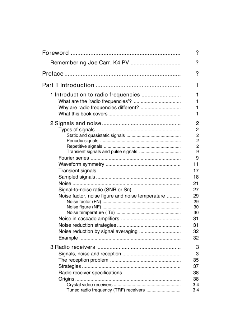
Foreword
Remembering Joe Carr, K4IPV
Preface
Part 1 Introduction
1 Introduction to radio frequencies
What are the 'radio frequencies'?
Why are radio frequencies different?
What this book covers
2 Signals and noise
Types of signals
Static and quasistatic signals
Periodic signals
Repetitive signals
Transient signals and pulse signals
Fourier series
Waveform symmetry
Transient signals
Sampled signals
Noise
Signal-to-noise ratio (SNR or Sn)
Noise factor, noise figure and noise temperature
Noise factor (FN)
Noise figure (NF)
Noise temperature ( Te)
Noise in cascade amplifiers
Noise reduction strategies
Noise reduction by signal averaging
Example
3 Radio receivers
Signals, noise and reception
The reception problem
Strategies
Radio receiver specifications
Origins
Crystal video receivers
Tuned radio frequency (TRF) receivers
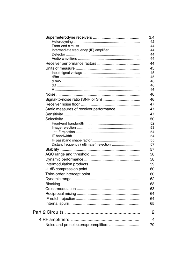
Superheterodyne receivers
Heterodyning
Front-end circuits
Intermediate frequency (IF) amplifier
Detector
Audio amplifiers
Receiver performance factors
Units of measure
Input signal voltage
dBm
dBmV
dB
V
Noise
Signal-to-noise ratio (SNR or Sn)
Receiver noise floor
Static measures of receiver performance
Sensitivity
Selectivity
Front-end bandwidth
Image rejection
1st IF rejection
IF bandwidth
IF passband shape factor
Distant frequency ('ultimate') rejection
Stability
AGC range and threshold
Dynamic performance
Intermodulation products
-1 dB compression point
Third-order intercept point
Dynamic range
Blocking
Cross-modulation
Reciprocal mixing
IF notch rejection
Internal spurii
Part 2 Circuits
4 RF amplifiers
Noise and preselectors/preamplifiers
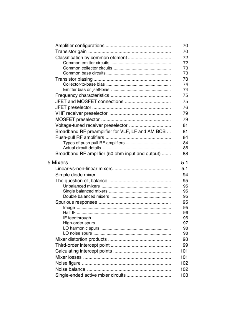
Amplifier configurations
Transistor gain
Classification by common element
Common emitter circuits
Common collector circuits
Common base circuits
Transistor biasing
Collector-to-base bias
Emitter bias or Îself-biasÌ
Frequency characteristics
JFET and MOSFET connections
JFET preselector
VHF receiver preselector
MOSFET preselector
Voltage-tuned receiver preselector
Broadband RF preamplifier for VLF, LF and AM BCB
Push-pull RF amplifiers
Types of push-pull RF amplifiers
Actual circuit details
Broadband RF amplifier (50 ohm input and output)
5 Mixers
Linear-vs-non-linear mixers
Simple diode mixer
The question of ÎbalanceÌ
Unbalanced mixers
Single balanced mixers
Double balanced mixers
Spurious responses
Image
Half IF
IF feedthrough
High-order spurs
LO harmonic spurs
LO noise spurs
Mixer distortion products
Third-order intercept point
Calculating intercept points
Mixer losses
Noise figure
Noise balance
Single-ended active mixer circuits
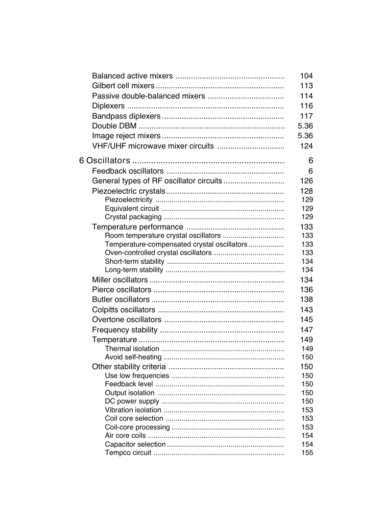
Balanced active mixers
Gilbert cell mixers
Passive double-balanced mixers
Diplexers
Bandpass diplexers
Double DBM
Image reject mixers
VHF/UHF microwave mixer circuits
6 Oscillators
Feedback oscillators
General types of RF oscillator circuits
Piezoelectric crystals
Piezoelectricity
Equivalent circuit
Crystal packaging
Temperature performance
Room temperature crystal oscillators
Temperature-compensated crystal oscillators
Oven-controlled crystal oscillators
Short-term stability
Long-term stability
Miller oscillators
Pierce oscillators
Butler oscillators
Colpitts oscillators
Overtone oscillators
Frequency stability
Temperature
Thermal isolation
Avoid self-heating
Other stability criteria
Use low frequencies
Feedback level
Output isolation
DC power supply
Vibration isolation
Coil core selection
Coil-core processing
Air core coils
Capacitor selection
Tempco circuit
Varactors
Frequency synthesizers
Reference section
Frequency synthesizer section
Output section
Automatic level control (ALC)
7 IF amplifiers and filters
IF filters: general filter theory
LÒ C IF filters
Crystal filters
Crystal ladder filters
Monolithic ceramic crystal filters
Mechanical filters
SAW filters
Filter switching in IF amplifiers
Amplifier circuits
Cascode pair amplifier
ÎUniversal’ IF amplifier
Coupling to block filters
More IC IF amplifiers
MC-1590 circuit
SL560C circuits
FM IF amplifier
Successive detection logarithmic amplifiers
8 Demodulators
AM envelope detectors
AM noise
Synchronous AM demodulation
Double sideband (DSBSC) and single sideband (SSBSC) suppressed carrier demodulators
Phasing method
FM and PM demodulator circuits
FosterÒ Seeley discriminator
Ratio detector
Pulse counting detector
Phase-locked loop FM/PM detectors
Quadrature detector
Part 3 Components
9 Capacitors
Units of capacitance
Breakdown voltage
Circuit symbols for capacitors
Fixed capacitors
Paper dielectric capacitors
Mylar dielectric capacitors
Ceramic dielectric capacitors
Mica dielectric capacitors
Other capacitors
Variable capacitors
Air variable main tuning capacitors
Capacitor tuning laws Ò SLC-vs-SLF
Special variable capacitors
Split stator capacitors
Differential capacitors
ÎTransmittingÌ variable capacitors
Variable capacitor cleaning note
Using and stabilizing a varactor diode
Varactor tuning circuits
Temperature compensation
Varactor applications
10 Inductors
Inductor circuit symbols
Inductance and inductors
Inductance of a single straight wire
Combining two or more inductors
Air-core inductors
Solenoid wound air-core inductors
Adjustable coils
Winding your own coils
Amidon Associates coil system
Using ferrite and powdered iron cores
Materials used in cores
Powdered iron
Ferrite materials
Making the calculations
Toroid cores
Example
Inductors and transformers
Broadband RF transformers
Winding toroid cores
Counting turns
Winding styles
Stabilizing the windings
Mounting toroids
Mounting multiple coils
Special mounting methods
High-power transformers
Binocular cores
Turns counting on binocular cores
Winding styles on binocular cores
Winding a binocular core
Ferrite rods
Bobbing along with a bobbin
Ferrite beads
Mounting ferrite beads
11 Tuning and matching
Vectors for RF circuits
LÒ C resonant tank circuits
Series resonant circuits
Parallel resonant circuits
Tuned RF/IF transformers
Construction of RF/IF transformers
Bandwidth of RF/IF transformers
Choosing component values for L– C resonant tank circuits
The tracking problem
The RF amplifier/antenna tuner problem
Example
The local oscillator (LO) problem
Trimmer capacitor method
Impedance matching in RF circuits
Transformer matching
Resonant transformers
Resonant networks
Inverse-L network
-network
Split-capacitor network
Transistor-to-transistor impedance matching
12 Splitters and hybrids
RF power combiners and splitters
Characteristics of splitter/combiner circuits
Resistive splitter/combiner
Transformer splitter/combiner
How it works
Mismatch losses
Modified VSWR bridge splitter/combiner
90 degree splitter/combiner
Transmission line splitter/combiners
90 degree transmission line splitter/combiner
Hybrid ring Îrat-raceÌ network
RF hybrid couplers
Applications of hybrids
Combining signal sources
Bi-directional amplifiers
Transmitter/receiver isolation
Quadrature hybrids
RF directional couplers
Conclusion
13 Monolithic microwave integrated circuits
Internal circuitry
Basic amplifier circuit
Other MAR-x circuits
Multiple device circuits
Mast-mounted wideband preamplifier
Broadband HF amplifier
Part 4 Measurement and techniques
14 Measuring inductors and capacitors
VSWR method
Voltage divider method
Signal generator method
Frequency shifted oscillator method
Using RF bridges
Maxwell bridge
Hay bridge
Schering bridge
Finding parasitic capacitances and inductances
Conclusion
15 RF power measurement
Power units
Types of RF power measurement
Methods for measuring RF power
Thermistor RF power meters
Bolometers
Self-balancing bridge instruments
Thermocouple RF power meters
Diode detector RF power meters
Circuits
Practical in-line bridge circuits
Micromatch
Monomatch
The Bird Thruline sensor
Calorimeters
Substitution flow calorimeters
Absolute flow calorimeters
Micropower and low power measurements
Error and uncertainty sources
Mismatch loss and mismatch uncertainty
16 Filtering against EMI/ RFI
Shielding
Filter circuits
RÒ C EMI/RFI protection
Feedthrough capacitors
General guidelines
17 Noise cancellation bridges
A simple bridge circuit
Bibliography
Index
RF Components and Circuits
RF Components and Circuits Joseph J. Carr Newnes OXFORD AMSTERDAM BOSTON LONDON NEW YORK PARIS SAN DIEGO SAN FRANCISCO SINGAPORE SYDNEY TOKYO
Newnes An imprint of Elsevier Science Linacre House, Jordan Hill, Oxford OX2 8DP 225 Wildwood Avenue, Woburn, MA 01801-2041 First edition 2002 Copyright © Joseph J. Carr and Elsevier Science Ltd 2002. All rights reserved The right of Joseph J. Carr to be identified as the author of this work has been asserted in accordance with the Copyright, Designs and Patents Act 1988 No part of this publication may be reproduced in any material form (including photocopying or storing in any medium by electronic means and whether or not transiently or incidentally to some other use of this publication) without the written permission of the copyright holder except in accordance with the provisions of the Copyright, Designs and Patents Act 1988 or under the terms of a licence issued by the Copyright Licensing Agency Ltd, 90 Tottenham Court Road, London, England W1T 4LP. Applications for the copyright holder’s written permission to reproduce any part of this publication should be addressed to the publishers British Library Cataloguing in Publication Data A catalogue record for this book is available from the British Library ISBN 0 7506 48449 Published in conjunction with Radio Society of Great Britain, Lambda House, Cranborne Road, Potters Bar, Herts, EN6 3JE. UK www.rsgb.org.uk For information on all Newnes publications visit our website at: newnespress.com Cover illustration supplied by Coilcraft Europe Ltd Composition by Genesis Typesetting, Rochester, Kent Printed and bound in Great Britain
Foreword ................................................................... ................................. Remembering Joe Carr, K4IPV Preface ....................................................................... Part 1 Introduction 1 Introduction to radio frequencies What are the ’radio frequencies’? Why are radio frequencies different? What this book covers 2 Signals and noise Types of signals Static and quasistatic signals Periodic signals Repetitive signals Transient signals and pulse signals Fourier series Waveform symmetry Transient signals Sampled signals Noise Signal-to-noise ratio (SNR or Sn) Noise factor, noise figure and noise temperature .................................................... .......................... .................................. ............................. .................................................... .................................................... ............................................................. ........................................... ................................................................ ............................................................. ................................. ................................................................. ...................................................... ............................................................ ............................................................. .............................................................................. ................................... .......... .............................................................. .............................................................. ................................................... ........................................... .............................................. .............................. ......................................................................... ....................................................... .......................................... ................................................... ....................................................................... ......................................... ............................................................................ ..................................................... ........................... Signals, noise and reception The reception problem Strategies Radio receiver specifications Origins Noise in cascade amplifiers Noise reduction strategies Noise reduction by signal averaging Example Crystal video receivers Tuned radio frequency (TRF) receivers Noise factor (FN) Noise figure (NF) Noise temperature ( Te) 3 Radio receivers ? ? ? 1 1 1 1 1 2 2 2 2 2 9 9 11 17 18 21 27 29 29 30 30 31 31 32 32 3 3 35 37 38 38 3.4 3.4
Superheterodyne receivers Heterodyning Front-end circuits Intermediate frequency (IF) amplifier Detector Audio amplifiers Receiver performance factors Units of measure Input signal voltage dBm dBmV dB V Noise Signal-to-noise ratio (SNR or Sn) Receiver noise floor Static measures of receiver performance Sensitivity Selectivity ............................................ .................................................................... .............................................................. ............................... ............................................................................ ................................................................ ........................................ ............................................................ .......................................................... .................................................................................. ................................................................................ ..................................................................................... ....................................................................................... .............................................................................. ................................... ....................................................... ...................... ....................................................................... ....................................................................... ........................................................ ................................................................. .................................................................. ..................................................................... ................................................. ............................. ........................................................................... .............................................. .................................................... ................................................ ................................................ .............................................. ............................................................... .......................................................................... ........................................................... ........................................................... ............................................................ .................................................................. Stability AGC range and threshold Dynamic performance Intermodulation products -1 dB compression point Third-order intercept point Dynamic range Blocking Cross-modulation Reciprocal mixing IF notch rejection Internal spurii Front-end bandwidth Image rejection 1st IF rejection IF bandwidth IF passband shape factor Distant frequency (’ultimate’) rejection Part 2 Circuits ........................................................... ........................................................... ............................. Noise and preselectors/preamplifiers 4 RF amplifiers 3.4 42 44 44 44 44 44 45 45 45 46 46 46 46 46 47 47 47 50 52 53 54 54 55 57 57 58 58 59 60 60 62 63 63 64 64 65 2 4 70
Types of push-pull RF amplifiers Actual circuit details Broadband RF amplifier (50 ohm input and output) 5 Mixers Common emitter circuits Common collector circuits Common base circuits Transistor biasing Amplifier configurations Transistor gain Classification by common element Collector-to-base bias Emitter bias or ˛self-bias Frequency characteristics JFET and MOSFET connections JFET preselector VHF receiver preselector MOSFET preselector Voltage-tuned receiver preselector Broadband RF preamplifier for VLF, LF and AM BCB Push-pull RF amplifiers .................................................. ............................................................... ................................. ................................................... ................................................ ...................................................... ........................................................... ...................................................... .................................................. .............................................. ................................... ............................................................ ............................................... ..................................................... ................................ ... .................................................. ...................................... .......................................................... ....... ....................................................................... ............................................ ......................................................... ............................................... ........................................................... .................................................... ................................................... ....................................................... ............................................................................... ............................................................................... .................................................................. ............................................................... ........................................................... ................................................................. ................................................ .............................................. ............................................ ................................................................... .................................................................... ................................................................ .................................. Mixer distortion products Third-order intercept point Calculating intercept points Mixer losses Noise figure Noise balance Single-ended active mixer circuits Linear-vs-non-linear mixers Simple diode mixer The question of ˛balance Unbalanced mixers Single balanced mixers Double balanced mixers Spurious responses Image Half IF IF feedthrough High-order spurs LO harmonic spurs LO noise spurs 70 70 72 72 73 73 73 74 74 75 75 76 79 79 81 81 84 84 86 88 5.1 5.1 94 95 95 95 95 95 95 96 96 97 98 98 98 99 101 101 102 102 103
6 Oscillators Feedback oscillators General types of RF oscillator circuits Piezoelectric crystals Piezoelectricity Equivalent circuit Crystal packaging Temperature performance Room temperature crystal oscillators Temperature-compensated crystal oscillators Oven-controlled crystal oscillators Short-term stability Long-term stability Balanced active mixers Gilbert cell mixers Passive double-balanced mixers Diplexers Bandpass diplexers Double DBM Image reject mixers VHF/UHF microwave mixer circuits .................................................. ........................................................... ................................... ........................................................................ ........................................................ ................................................................... ........................................................ ............................... ................................................................ ...................................................... ............................ ...................................................... ................................................................. .............................................................. ............................................................. ............................................. ............................... .................. .................................... ........................................................... ............................................................ .............................................................. ............................................................ ............................................................. .......................................................... ....................................................... ......................................................... ................................................................... .............................................................. ............................................................. ..................................................... ......................................................... ................................................................. ................................................................ .............................................................. ............................................................. ............................................................ ......................................................... ..................................................................... ........................................................... .................................................................. Miller oscillators Pierce oscillators Butler oscillators Colpitts oscillators Overtone oscillators Frequency stability Temperature Thermal isolation Avoid self-heating Other stability criteria Use low frequencies Feedback level Output isolation DC power supply Vibration isolation Coil core selection Coil-core processing Air core coils Capacitor selection Tempco circuit 104 113 114 116 117 5.36 5.36 124 6 6 126 128 129 129 129 133 133 133 133 134 134 134 136 138 143 145 147 149 149 150 150 150 150 150 150 153 153 153 154 154 155
分享到:
收藏