Allen-Bradley I/O
Modules
1732, 1734, 1734D, 1738, 1746,
1747, 1756, 1761, 1762, 1764,
1769, 1771, 1790, 1791, 1791D,
1791P, 1791R, 1792D, 1794,
1797, 1798, 1799
Wiring Diagrams
�
Important User Information Solid state equipment has operational characteristics differing from those of
electromechanical equipment. Safety Guidelines for the Application, Installation and
Maintenance of Solid State Controls (Publication SGI-1.1 available from your local
Rockwell Automation sales office or online at
http://www.literature.rockwellautomation.com) describes some important differences
between solid state equipment and hard-wired electromechanical devices. Because of
this difference, and also because of the wide variety of uses for solid state equipment,
all persons responsible for applying this equipment must satisfy themselves that each
intended application of this equipment is acceptable.
In no event will Rockwell Automation, Inc. be responsible or liable for indirect or
consequential damages resulting from the use or application of this equipment.
The examples and diagrams in this manual are included solely for illustrative purposes.
Because of the many variables and requirements associated with any particular
installation, Rockwell Automation, Inc. cannot assume responsibility or liability for
actual use based on the examples and diagrams.
No patent liability is assumed by Rockwell Automation, Inc. with respect to use of
information, circuits, equipment, or software described in this manual.
Reproduction of the contents of this manual, in whole or in part, without written
permission of Rockwell Automation, Inc. is prohibited.
Throughout this manual, when necessary, we use notes to make you aware of
safety considerations.
WARNING
Identifies information about practices or circumstances
that can cause an explosion in a hazardous environment,
which may lead to personal injury or death, property
damage, or economic loss.
IMPORTANT
Identifies information that is critical for successful
application and understanding of the product.
ATTENTION
Identifies information about practices or circumstances that can
lead to personal injury or death, property damage, or economic
loss. Attentions help you identify a hazard, avoid a hazard and
recognize the consequences.
SHOCK HAZARD
Labels may be located on or inside the drive to alert
people that dangerous voltage may be present.
BURN HAZARD
Labels may be located on or inside the drive to alert
people that surfaces may be dangerous temperatures.
�
Introduction
Preface
The purpose for showing these connection diagrams here is to
illustrate the following attributes of each I/O module, I/O block, or
fixed I/O controller:
• the number of inputs and/or outputs
• whether there is a single common for all I/O, a common for a
set of I/O separate from other sets of I/O, or a signal return for
each I/O circuit so that each I/O circuit is isolated from all
others
• whether an output is a current source or a current sink
• whether an input is a source load or a sink load
To fit them into this concise format, these diagrams are intentionally
simplified to the point that they do not show the type of cables,
twisted pairs, cable shields or the grounding of cable shields. We
make an exception where the cable shield must be connected at an
I/O terminal.
For those input modules or blocks that can tolerate the leakage
current of proximity sensors, we usually show a proximity sensor at
one input and hard contacts at the others for ease of illustration.
IMPORTANT
Many of the catalog numbers included in this
publication have specific wiring guidelines and
recommendations that are listed in the products
technical documentation (e.g. installation instructions
or user manuals) but not here because the purpose
of this publication is to show connection diagrams
and basic information required to wire each I/O
module.
For a full description of how to use each of the
catalog numbers listed in this publication, see the
individual products technical documentation.
1
Publication CIG-WD001B-EN-P - May 2005
�
Preface 2
Abbreviations
In these diagrams we used the following abbreviations:
no
nc
n.c.
normally open (contact outputs)
normally closed (contact outputs)
no connection (do not connect to this terminal)
Symbols
In these diagrams we used the following symbols:
ac power source
ac/dc power source
dc power source
output load
current-signal analog sensor
voltage-signal analog sensor
RTD
thermocouple
3-wire proximity sensor
4-wire proximity sensor
hard-contact switching devices
TTL switching device
+
+
+
Prox
+or
TTL
Publication CIG-WD001B-EN-P - May 2005
�
Table of Contents
Chapter 1
1732 ArmorBlock I/O . . . . . . . . . . . . . . . . . . . . . . . . . . . . . . . . . 1-1
Chapter 2
1734 POINT I/O Modules. . . . . . . . . . . . . . . . . . . . . . . . . . . . . . 2-1
Chapter 3
1734D POINTBlock I/O Modules . . . . . . . . . . . . . . . . . . . . . . . 3-1
Chapter 4
1738 ArmorPoint. . . . . . . . . . . . . . . . . . . . . . . . . . . . . . . . . . . . . . 4-1
Chapter 5
1746 I/O Modules. . . . . . . . . . . . . . . . . . . . . . . . . . . . . . . . . . . . . 5-1
Chapter 6
1747 I/O on Fixed Hardware Controllers . . . . . . . . . . . . . . . . . . 6-1
Chapter 7
1756 ControlLogix I/O Modules . . . . . . . . . . . . . . . . . . . . . . . . . 7-1
Chapter 8
1761 Controller I/O on MicroLogix 1000 Controllers . . . . . . . . 8-1
Chapter 9
1762 I/O on MicroLogix 1200 Controllers . . . . . . . . . . . . . . . . . 9-1
Chapter 10
1764 Controller I/O on MicroLogix 1500 Controllers . . . . . . . 10-1
Chapter 11
1769 Compact I/O Modules. . . . . . . . . . . . . . . . . . . . . . . . . . . . 11-1
Chapter 12
1771 I/O Modules. . . . . . . . . . . . . . . . . . . . . . . . . . . . . . . . . . . . 12-1
Chapter 13
1790 CompactBlock LDX I/O Modules . . . . . . . . . . . . . . . . . . 13-1
Chapter 14
1791 I/O Blocks . . . . . . . . . . . . . . . . . . . . . . . . . . . . . . . . . . . . . 14-1
1
Publication CIG-WD001B-EN-P - May 2005
�
Table of Contents 2
Chapter 15
1791D CompactBlock I/O Blocks . . . . . . . . . . . . . . . . . . . . . . . 15-1
Chapter 16
1791P CompactBlock I/O Blocks . . . . . . . . . . . . . . . . . . . . . . . . . . 16-1
Chapter 17
1791R CompactBlock I/O Blocks . . . . . . . . . . . . . . . . . . . . . . . 17-1
Chapter 18
1792D ArmorBlock MaXum I/O Blocks . . . . . . . . . . . . . . . . . 18-1
Chapter 19
1794 FLEX I/O Modules . . . . . . . . . . . . . . . . . . . . . . . . . . . . . . 19-1
Chapter 20
1797 FLEX Ex Modules . . . . . . . . . . . . . . . . . . . . . . . . . . . . . . . 20-1
Chapter 21
1798 FLEX Armor I/O Modules. . . . . . . . . . . . . . . . . . . . . . . . 21-1
Chapter 22
1799 Embedded I/O Cards . . . . . . . . . . . . . . . . . . . . . . . . . . . . 22-1
Publication CIG-WD001B-EN-P - May 2005
�
Chapter 1
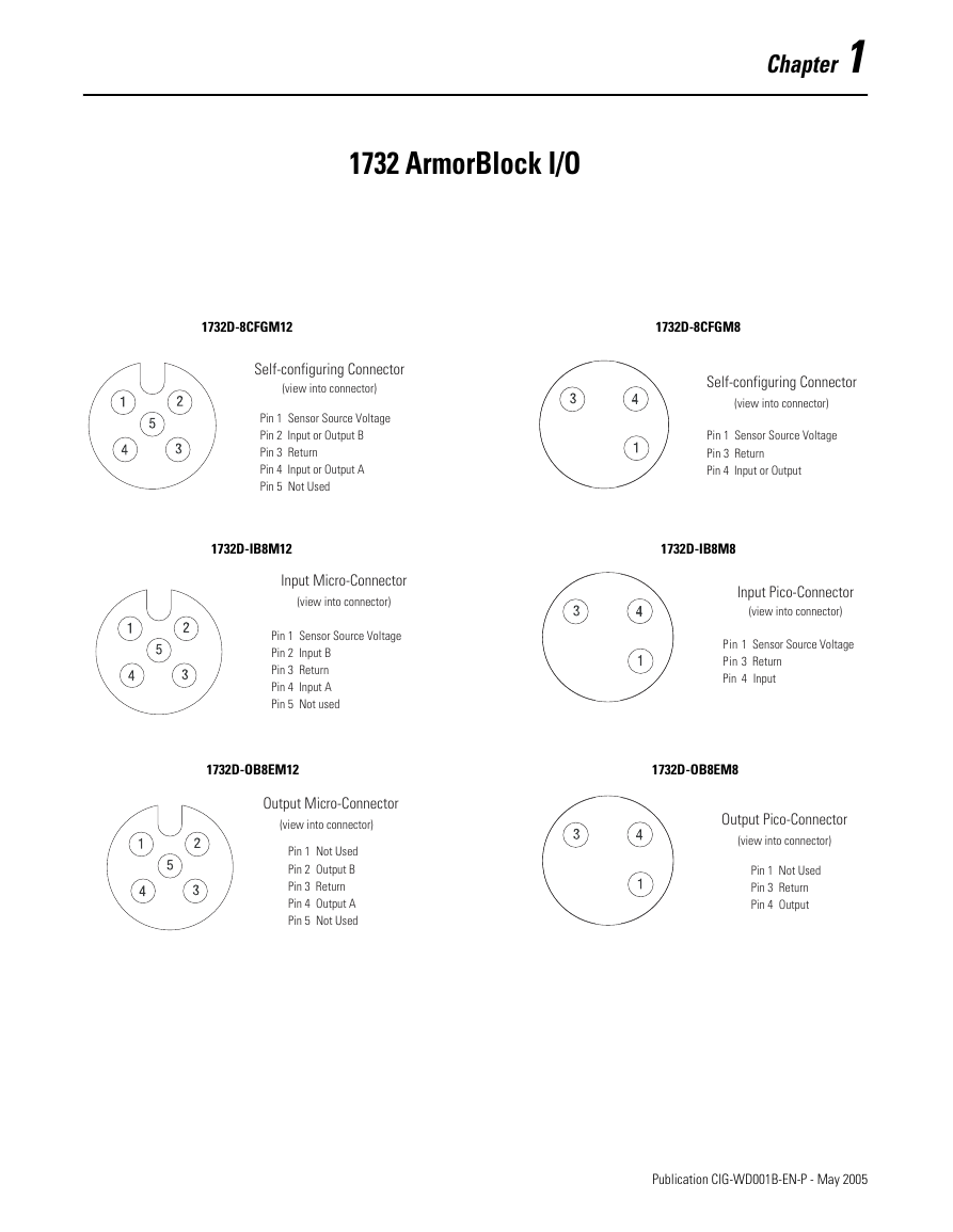
1732 ArmorBlock I/O
1732D-8CFGM12
1732D-8CFGM8
Self-configuring Connector
(view into connector)
Pin 1 Sensor Source Voltage
Pin 2 Input or Output B
Pin 3 Return
Pin 4 Input or Output A
Pin 5 Not Used
Self-configuring Connector
(view into connector)
Pin 1 Sensor Source Voltage
Pin 3 Return
Pin 4 Input or Output
1732D-IB8M12
1732D-IB8M8
Input Micro-Connector
(view into connector)
Pin 1 Sensor Source Voltage
Pin 2 Input B
Pin 3 Return
Pin 4 Input A
Pin 5 Not used
Input Pico-Connector
(view into connector)
Pin 1 Sensor Source Voltage
Pin 3 Return
Pin 4 Input
1732D-OB8EM12
1732D-OB8EM8
Output Micro-Connector
(view into connector)
Pin 1 Not Used
Pin 2 Output B
Pin 3 Return
Pin 4 Output A
Pin 5 Not Used
Output Pico-Connector
(view into connector)
Pin 1 Not Used
Pin 3 Return
Pin 4 Output
1
Publication CIG-WD001B-EN-P - May 2005
�
1-2 1732 ArmorBlock I/O
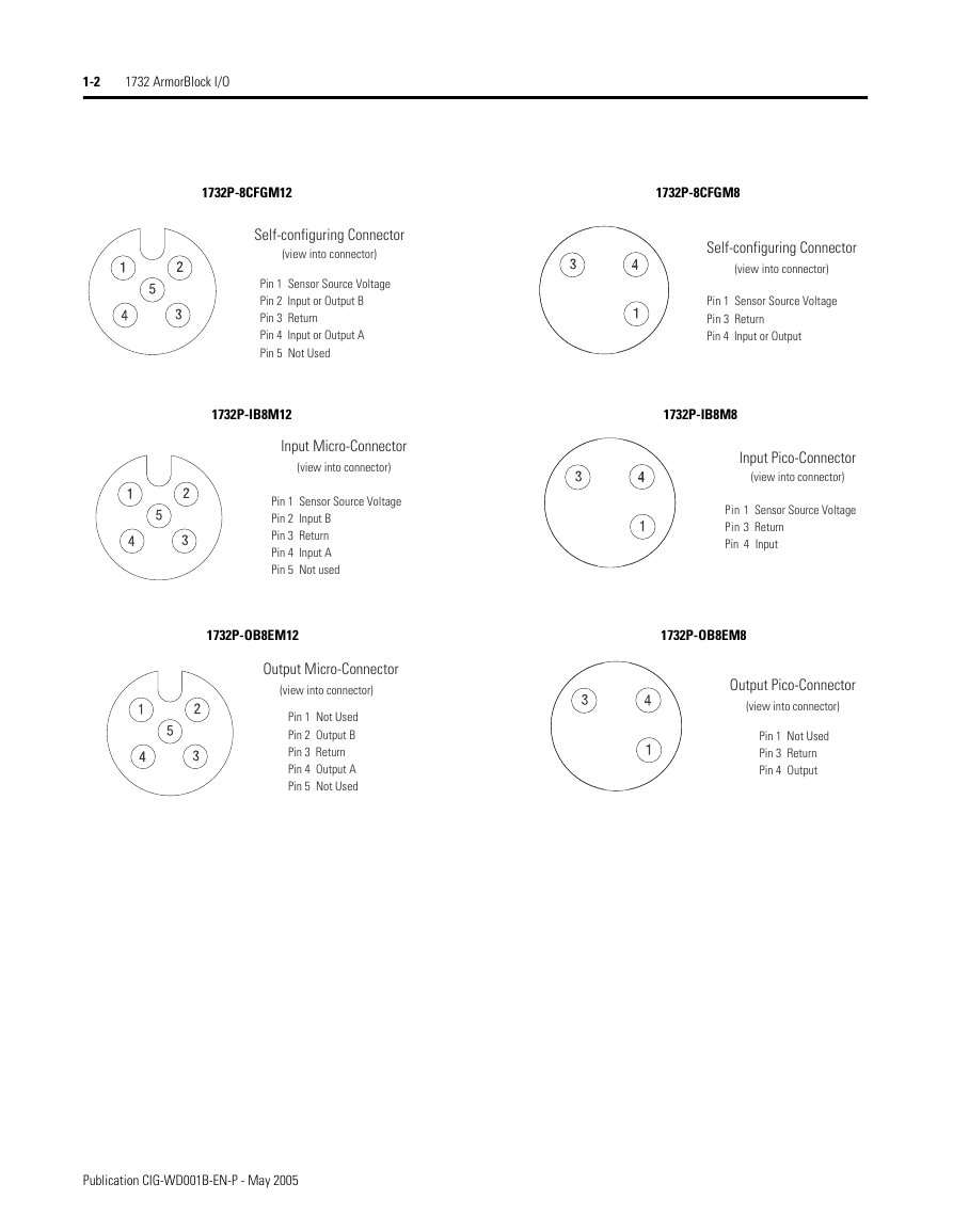
1732P-8CFGM12
1732P-8CFGM8
Self-configuring Connector
(view into connector)
Pin 1 Sensor Source Voltage
Pin 2 Input or Output B
Pin 3 Return
Pin 4 Input or Output A
Pin 5 Not Used
Self-configuring Connector
(view into connector)
Pin 1 Sensor Source Voltage
Pin 3 Return
Pin 4 Input or Output
1732P-IB8M12
1732P-IB8M8
Input Micro-Connector
(view into connector)
Pin 1 Sensor Source Voltage
Pin 2 Input B
Pin 3 Return
Pin 4 Input A
Pin 5 Not used
Input Pico-Connector
(view into connector)
Pin 1 Sensor Source Voltage
Pin 3 Return
Pin 4 Input
1732P-OB8EM12
1732P-OB8EM8
Output Micro-Connector
(view into connector)
Pin 1 Not Used
Pin 2 Output B
Pin 3 Return
Pin 4 Output A
Pin 5 Not Used
Output Pico-Connector
(view into connector)
Pin 1 Not Used
Pin 3 Return
Pin 4 Output
Publication CIG-WD001B-EN-P - May 2005
�




 2023年江西萍乡中考道德与法治真题及答案.doc
 2012年重庆南川中考生物真题及答案.doc
 2013年江西师范大学地理学综合及文艺理论基础考研真题.doc
 2020年四川甘孜小升初语文真题及答案I卷.doc
 2020年注册岩土工程师专业基础考试真题及答案.doc
 2023-2024学年福建省厦门市九年级上学期数学月考试题及答案.doc
 2021-2022学年辽宁省沈阳市大东区九年级上学期语文期末试题及答案.doc
 2022-2023学年北京东城区初三第一学期物理期末试卷及答案.doc
 2018上半年江西教师资格初中地理学科知识与教学能力真题及答案.doc
 2012年河北国家公务员申论考试真题及答案-省级.doc
 2020-2021学年江苏省扬州市江都区邵樊片九年级上学期数学第一次质量检测试题及答案.doc
 2022下半年黑龙江教师资格证中学综合素质真题及答案.doc