Calculation and hue mapping of AoP
in polarization imaging
Feng, Bin, Guo, Rongli, Zhang, Faqiang, Zhao, Feng,
Dong, Yue
Bin Feng, Rongli Guo, Faqiang Zhang, Feng Zhao, Yue Dong, "Calculation
and hue mapping of AoP in polarization imaging," Proc. SPIE 11052, Third
International Conference on Photonics and Optical Engineering, 110521V (24
January 2019); doi: 10.1117/12.2523643
Event: The International Conference on Photonics and Optical Engineering,
2018, Xi'an, China
Downloaded From: https://www.spiedigitallibrary.org/conference-proceedings-of-spie on 28 Dec 2019 Terms of Use: https://www.spiedigitallibrary.org/terms-of-use
PROCEEDINGS OF SPIESPIEDigitalLibrary.org/conference-proceedings-of-spie�
Downloaded From: https://www.spiedigitallibrary.org/conference-proceedings-of-spie on 28 Dec 2019
Terms of Use: https://www.spiedigitallibrary.org/terms-of-use
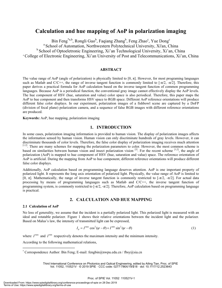
Calculation and hue mapping of AoP in polarization imaging Bin Feng*a,b, Rongli Guob, Faqiang Zhangb, Feng Zhaoc, Yue Dongc a School of Automation, Northwestern Polytechnical University, Xi'an, China b School of Optoeletronic Engineering, Xi’an Technological University, Xi’an, China c College of Electronic Engineering, Xi’an University of Post and Telecommunications, Xi’an, China ABSTRACT The value range of AoP (angle of polarization) is physically limited to [0, π]. However, for most programing languages such as Matlab and C/C++, the range of inverse tangent function is commonly limited to [-π/2, -π/2]. Therefore, this paper derives a practical formula for AoP calculation based on the inverse tangent function of common programming languages. Because AoP is a periodical function, the conventional gray image cannot effectively display the AoP levels. The hue component of HSV (hue, saturation and value) color space is also periodical. Therefore, this paper maps the AoP to hue component and then transforms HSV space to RGB space. Different AoP reference orientations will produce different false color displays. In our experiment, polarization images of a fishbowl scene are captured by a DoFP (division of focal plane) polarization camera, and a sequence of false RGB images with different reference orientations are produced. Keywords: AoP, hue mapping, polarization imaging 1. INTRODUCTION In some cases, polarization imaging information is provided to human vision. The display of polarization images affects the information sensed by human vision. Human vision can only discriminate hundreds of gray levels. However, it can discriminate thousands of color levels. Therefore, the false color display of polarization imaging receives much attention [1,2]. There are many schemes for mapping the polarization parameters to color. However, the most common scheme is based on similarities between human vision and insect polarization vision [3]. For the recent scheme [1,2], the angle of polarization (AoP) is mapped to hue component of HSV (hue, saturation and value) space. The reference orientation of AoP is artificial. During the mapping from AoP to hue component, different reference orientations will produce different false color displays. Additionally, AoP calculation based on programming language deserves attention. AoP is one important property of polarized light. It represents the long axis orientation of polarized light. Physically, the value range of AoP is limited to [0, π]. Mathematically, the range of inverse tangent function is commonly restricted to [-π/2, -π/2]. For actual data processing by means of programming languages such as Matlab and C/C++, the inverse tangent function of programming system, is commonly restricted to [-π/2, -π/2]. Therefore, AoP calculation based on programming language is practical. 2. CALCULATION AND HUE MAPPING 2.1 Calculation of AoP No loss of generality, we assume that the incident is a partially polarized light. This polarized light is measured with an ideal and rotatable polarizer. Figure 1 shows their relative orientations between the incident light and the polarizer. Based on Malus’s law, the intensity of transmitted light can be expressed, max2min2cos()sin()IIIθψθψθ=−+− (1) where maxI and minI respectively denotes the maximum intensity and the minimum intensity. According to the following mathematical relations, * Correspondence Author: Bin Feng; E-mail: fengbin@nwpu.edu.cn / fbsy@sia.cn Third International Conference on Photonics and Optical Engineering, edited by Ailing Tian, Proc. of SPIE Vol. 11052, 110521V · © 2019 SPIE · CCC code: 0277-786X/19/$18 · doi: 10.1117/12.2523643Proc. of SPIE Vol. 11052 110521V-1�
Downloaded From: https://www.spiedigitallibrary.org/conference-proceedings-of-spie on 28 Dec 2019
Terms of Use: https://www.spiedigitallibrary.org/terms-of-use
Short axis ofpartially polarizedincident lightLong axis ofpartially polarizedincident lightaTransmissionW axis of a idealpolarizerbReferenceorientation 21cos[2()]cos()2ψθψθ+−−= (2) 21cos[2()]sin()2ψθψθ−−−= (3) Figure 1. Relative orientations between a partially polarized light and an ideal polarizer. The Equation (1) is rewritten as, maxminmaxmin1[()()cos[2()]2IIIIIθψθ=++−− (4) Let θ be set to 0,45,90,135 degrees, and we can obtain the following expression, maxminmaxmin0maxminmaxmin45maxminmaxmin90maxminmaxmin135()()cos(2)()()sin(2)1=2()()cos(2)()()sin(2)IIIIIIIIIIIIIIIIIIIIψψψψ⎡⎤⎡⎤++−⎢⎥⎢⎥++−⎢⎥⎢⎥⎢⎥⎢⎥+−−⎢⎥⎢⎥+−−⎢⎥⎣⎦⎣⎦ (5) where 0ψπ<<. The Stokes vector of the incident light is given, 004590135109024513512()sIIIIsIIsII=+++=−=− (6) Submitting Equation (5) into Equation (6), we can obtain, maxmin0maxmin1maxmin2()cos(2)()sin(2)sIIsIIsIIψψ=+=−=−. (7) With maxmin()0II−≥, 1sandcos(2)ψ have the same symbol, and2sand sin(2)ψ have the same symbol. Commonly, the inverse tangent function is restricted to [2,2]ππ−+ , accordingly, the following expression holds, 21arctan()[2,+2]ssππ∈− (8) Then, 2112arctan()[4,+4]ssππ∈− (9) Evidently,ψand 2112arctan()ss have different ranges of value. However, the following equation is widely cited in many references [2], Proc. of SPIE Vol. 11052 110521V-2�
Downloaded From: https://www.spiedigitallibrary.org/conference-proceedings-of-spie on 28 Dec 2019
Terms of Use: https://www.spiedigitallibrary.org/terms-of-use
2112arctan()ssψ= (10) Sometimes, this difference between ψand 2112arctan()ss is neglected. This neglect may mislead readers to obtain the wrong results. Because 1sand sin(2)ψhave the same symbol, and2sand cos(2)ψ have the same symbol, we use the symbols of 1s and 2s to restrict the parameter. The symbols of 1s and 2scan be divided into four cases. Case I:10s> and 20s> Accordingly, cos(2)0ψ>and sin(2)0ψ> jointly prove that 2ψ belongs to Quadrant I. Thus, 2[0,2]ψπ∈. 212=arctan()ssψ (11) Case II:10s< and 20s> Accordingly, cos(2)0ψ< and sin(2)0ψ> jointly prove that 2ψbelongs to Quadrant II. With 21arctan(/)[-2,0]ssπ∈, then. 212=arctan()+ssψπ (12) Case III:10s< and20s< Accordingly, cos(2)0ψ< and sin(2)0ψ< jointly prove that 2ψ belongs to Quadrant III. With 21arctan(/)[0,2]ssπ∈, then, 212=arctan()+ssψπ (13) Case IV:10s>and 20s< Accordingly,cos(2)0ψ>andsin(2)0ψ>⎧⎪+<⎨⎪><⎩ (15) Additionally, based on Stokes vector of Expression (6), the DoLP (degree of linear polarization) can be calculated by the following expression [4], 22120DoLP=sss+ (16) 2.2 Hue mapping AoP is periodical. The common gray image represents large value with “white”, less value with dark and middle value with “gray”. Therefore, the gray image cannot correctly display the AoP levels. By comparison, the hue component of HSV color space is also periodical. Based on similarities between human vision and insect polarization vision [3], the most common scheme maps the AoP to hue component of HSV color space by the following expression, 2Hψ→ (17) Proc. of SPIE Vol. 11052 110521V-3�
Downloaded From: https://www.spiedigitallibrary.org/conference-proceedings-of-spie on 28 Dec 2019
Terms of Use: https://www.spiedigitallibrary.org/terms-of-use
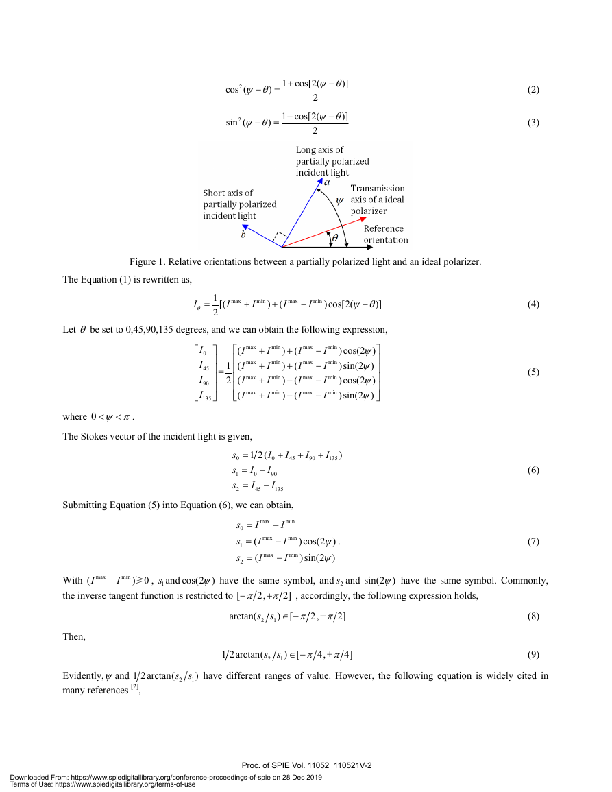
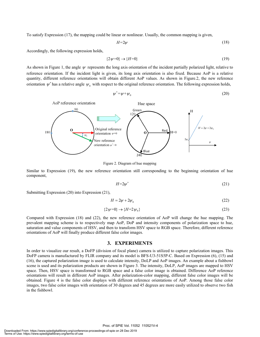
180AoP reference orientation90Original referenceorientation w=0New referenceorientation /=0Hue spaceH=02WoH = 2yi + 2yioTo satisfy Expression (17), the mapping could be linear or nonlinear. Usually, the common mapping is given, =2Hψ (18) Accordingly, the following expression holds, {2=0}{=0}Hψ→ (19) As shown in Figure 1, the angle ψ represents the long axis orientation of the incident partially polarized light, relative to reference orientation. If the incident light is given, its long axis orientation is also fixed. Because AoP is a relative quantity, different reference orientations will obtain different AoP values. As shown in Figure.2, the new reference orientation ψ∗has a relative angle 0ψ with respect to the original reference orientation. The following expression holds, *0=+ψψψ (20) Figure 2. Diagram of hue mapping Similar to Expression (19), the new reference orientation still corresponding to the beginning orientation of hue component, =2Hψ∗ (21) Submitting Expression (20) into Expression (21), 022Hψψ=+ (22) 0{2=0}{=2}Hψψ→ (23) Compared with Expression (18) and (22), the new reference orientation of AoP will change the hue mapping. The prevalent mapping scheme is to respectively map AoP, DoP and intensity components of polarization space to hue, saturation and value components of HSV, and then to transform HSV space to RGB space. Therefore, different reference orientations of AoP will finally produce different false color images. 3. EXPERIMENTS In order to visualize our result, a DoFP (division of focal plane) camera is utilized to capture polarization images. This DoFP camera is manufactured by FLIR company and its model is BFS-U3-51S5P-C. Based on Expression (6), (15) and (16), the captured polarization image is used to calculate intensity, DoLP and AoP images. An example about a fishbowl scene is used and its polarization products are shown in Figure 3. The intensity, DoLP, AoP images are mapped to HSV space. Then, HSV space is transformed to RGB space and a false color image is obtained. Difference AoP reference orientations will result in different AoP images. After polarization-color mapping, different false color images will be obtained. Figure 4 is the false color displays with different reference orientations of AoP. Among those false color images, two false color images with orientation of 30 degrees and 45 degrees are more easily utilized to observe two fish in the fishbowl. Proc. of SPIE Vol. 11052 110521V-4�
Downloaded From: https://www.spiedigitallibrary.org/conference-proceedings-of-spie on 28 Dec 2019
Terms of Use: https://www.spiedigitallibrary.org/terms-of-use
Figure 3. Polarization products Figure 4. False color displays with different reference orientations of AoP. Proc. of SPIE Vol. 11052 110521V-5�
Downloaded From: https://www.spiedigitallibrary.org/conference-proceedings-of-spie on 28 Dec 2019
Terms of Use: https://www.spiedigitallibrary.org/terms-of-use
4. CONCLUSIONS This paper discusses that different reference orientations of AoP will produce different false color displays. For human vision, those false color images have different image quality. The quantitative evaluation of those false color images will lay a foundation for optimal selection of AoP reference orientation. This deserves further research. This research was funded by Natural Science Basic Research Plan in Shaanxi Province of China (2018JM6041), Natural Science Foundation of China (NSFC) (61605152) and China Postdoctoral Science Foundation (2017M621174). REFERENCES [1] Kruse A W, Alenin A S, Vaughn I J, Tyo J S, “Polarization-color mapping strategies: catching up with color theory,” Proc. of SPIE 10407, 10407G (2017). [2] Tyo J S, Ratliff B M, Alenin A S, “Adapting the HSV polarization-color mapping for regions with low irradiance and high polarization,” Optics letters, 41(20), 4759-4762(2016). [3] Bernard G D, Wehner R. “Functional similarities between polarization vision and color vision,” Vision Research, 17(9), 1019-1028(1977). [4] Feng B, Shi Z L, Xu B S, Zhang C S, “Polarized-pixel performance model for DoFP polarimeter,” Journal of Optics, 20, 065703(2018). Proc. of SPIE Vol. 11052 110521V-6�



 2023年江西萍乡中考道德与法治真题及答案.doc
 2012年重庆南川中考生物真题及答案.doc
 2013年江西师范大学地理学综合及文艺理论基础考研真题.doc
 2020年四川甘孜小升初语文真题及答案I卷.doc
 2020年注册岩土工程师专业基础考试真题及答案.doc
 2023-2024学年福建省厦门市九年级上学期数学月考试题及答案.doc
 2021-2022学年辽宁省沈阳市大东区九年级上学期语文期末试题及答案.doc
 2022-2023学年北京东城区初三第一学期物理期末试卷及答案.doc
 2018上半年江西教师资格初中地理学科知识与教学能力真题及答案.doc
 2012年河北国家公务员申论考试真题及答案-省级.doc
 2020-2021学年江苏省扬州市江都区邵樊片九年级上学期数学第一次质量检测试题及答案.doc
 2022下半年黑龙江教师资格证中学综合素质真题及答案.doc