logo资料库

BCM2711 外设数据手册.pdf

第1页 / 共164页
第2页 / 共164页
第3页 / 共164页
第4页 / 共164页
第5页 / 共164页
第6页 / 共164页
第7页 / 共164页
第8页 / 共164页
资料共164页,剩余部分请下载后查看
BCM2711 ARM Peripherals
Colophon
Legal Disclaimer Notice
Table of Contents
Chapter 1. Introduction
1.1. Overview
1.2. Address map
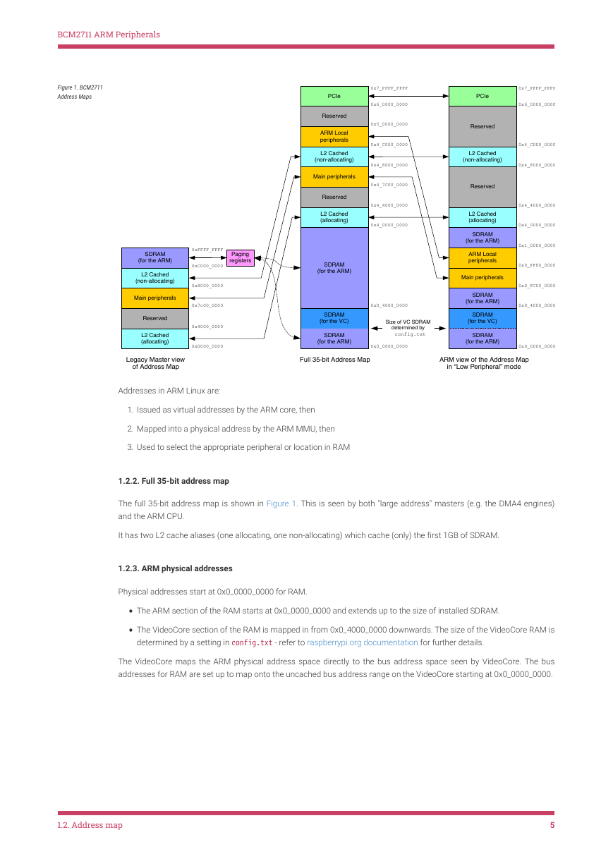
1.2.1. Diagrammatic overview
1.2.2. Full 35-bit address map
1.2.3. ARM physical addresses
1.2.4. Legacy master addresses
1.3. Peripheral access precautions for correct memory ordering
Chapter 2. Auxiliaries: UART1, SPI1 & SPI2
2.1. Overview
2.1.1. AUX registers
2.2. Mini UART
2.2.1. Mini UART implementation details
2.2.2. Mini UART register details
2.3. Universal SPI Master (2x)
2.3.1. SPI implementation details
2.3.2. Interrupts
2.3.3. Long bit streams
2.3.4. SPI register details
Chapter 3. BSC
3.1. Overview
3.2. Register View
3.3. 10-Bit Addressing
3.3.1. Writing
3.3.2. Reading
Chapter 4. DMA Controller
4.1. Overview
4.2. DMA Controller Registers
4.2.1. DMA Channel Register Address Map
4.2.1.1. Control Block Data Structure
4.2.1.2. Register Map
4.2.1.3. Peripheral DREQ Signals
4.3. AXI Bursts
4.4. Error Handling
4.5. DMA LITE Engines
4.6. DMA4 Engines
Chapter 5. General Purpose I/O (GPIO)
5.1. Overview
5.2. Register View
5.3. Alternative Function Assignments
5.4. General Purpose GPIO Clocks
5.4.1. Operating Frequency
5.4.2. Register Definitions
Chapter 6. Interrupts
6.1. Overview
6.2. Interrupt sources
6.2.1. ARM Core n interrupts
6.2.2. ARM_LOCAL interrupts
6.2.3. ARMC interrupts
6.2.4. VideoCore interrupts
6.2.5. ETH_PCIe interrupts
6.3. GIC-400 interrupt controller
6.4. Legacy interrupt controller
6.5. Registers
6.5.1. GIC-400
6.5.2. ARM_LOCAL
6.5.3. ARMC
Chapter 7. PCM / I2S Audio
7.1. Overview
7.2. Block Diagram
7.3. Typical Timing
7.4. Operation
7.5. Software Operation
7.5.1. Operating in Polled mode
7.5.2. Operating in Interrupt mode
7.5.3. DMA
7.6. Error Handling
7.7. PDM Input Mode Operation
7.8. GRAY Code Input Mode Operation
7.9. PCM Register Map
Chapter 8. Pulse Width Modulator
8.1. Overview
8.2. Block Diagram
8.3. PWM Implementation
8.4. Modes of Operation
8.5. Quick Reference
8.6. Control and Status Registers
Chapter 9. SPI
9.1. Overview
9.2. SPI Master Mode
9.2.1. Standard mode
9.2.2. Bidirectional mode
9.3. LoSSI mode
9.3.1. Command write
9.3.2. Parameter write
9.3.3. Byte read commands
9.3.4. 24-bit read command
9.3.5. 32-bit read command
9.4. Block Diagram
9.5. SPI Register Map
9.6. Software Operation
9.6.1. Polled
9.6.2. Interrupt
9.6.3. DMA
9.6.4. Notes
Chapter 10. System Timer
10.1. Overview
10.2. System Timer Registers
Chapter 11. UART
11.1. Overview
11.2. Variations from the 16C650 UART
11.3. Primary UART Inputs and Outputs
11.4. UART Interrupts
11.5. Register View
Chapter 12. Timer (ARM side)
12.1. Overview
12.2. Timer Registers
Chapter 13. ARM Mailboxes
13.1. Overview
13.2. Registers
BCM2711 ARM Peripherals Colophon BCM2711 ARM Peripherals, based in large part on the earlier BCM2835 ARM Peripherals documentation. © 2012 Broadcom Europe Ltd., 2020 Raspberry Pi (Trading) Ltd. All rights reserved. build-date: 2020-10-16 build-version: githash: bfc2f1f-clean Table 1. Release History Release Date Description 1 2 3 05/Feb/2020 First release. 24/Sep/2020 Corrected GPIO base address. Updated styling. 16/Oct/2020 First public release. The latest release can be found at http://datasheets.raspberrypi.org/bcm2711/bcm2711-peripherals.pdf. Legal Disclaimer Notice TECHNICAL AND RELIABILITY DATA FOR RASPBERRY PI PRODUCTS (INCLUDING DATASHEETS) AS MODIFIED FROM TIME TO TIME (“RESOURCES”) ARE PROVIDED BY RASPBERRY PI (TRADING) LTD (“RPTL) "AS IS" AND ANY EXPRESS OR IMPLIED WARRANTIES, INCLUDING, BUT NOT LIMITED TO, THE IMPLIED WARRANTIES OF MERCHANTABILITY AND FITNESS FOR A PARTICULAR PURPOSE ARE DISCLAIMED. TO THE MAXIMUM EXTENT PERMITTED BY APPLICABLE LAW IN NO EVENT SHALL RPTL BE LIABLE FOR ANY DIRECT, INDIRECT, INCIDENTAL, SPECIAL, EXEMPLARY, OR CONSEQUENTIAL DAMAGES (INCLUDING, BUT NOT LIMITED TO, PROCUREMENT OF SUBSTITUTE GOODS OR SERVICES; LOSS OF USE, DATA, OR PROFITS; OR BUSINESS INTERRUPTION) HOWEVER CAUSED AND ON ANY THEORY OF LIABILITY, WHETHER IN CONTRACT, STRICT LIABILITY, OR TORT (INCLUDING NEGLIGENCE OR OTHERWISE) ARISING IN ANY WAY OUT OF THE USE OF THE RESOURCES, EVEN IF ADVISED OF THE POSSIBILITY OF SUCH DAMAGE. RPTL reserves the right to make any enhancements, improvements, corrections or any other modifications to the RESOURCES or any products described in them at any time and without further notice. The RESOURCES are intended for skilled users with suitable levels of design knowledge. Users are solely responsible for their selection and use of the RESOURCES and any application of the products described in them. User agrees to indemnify and hold RPTL harmless against all liabilities, costs, damages or other losses arising out of their use of the RESOURCES. RPTL grants users permission to use the RESOURCES solely in conjunction with the Raspberry Pi products. All other use of the RESOURCES is prohibited. No licence is granted to any other RPTL or other third party intellectual property right. HIGH RISK ACTIVITIES. Raspberry Pi products are not designed, manufactured or intended for use in hazardous environments requiring fail safe performance, such as in the operation pf nuclear facilities, aircraft navigation or communication systems, air traffic control, weapons systems or safety-critical applications (including life support systems and other medical devices), in which the failure of the products could lead directly to death, personal injury or severe physical or environmental damage (“High Risk Activities”). RPTL specifically disclaims any express or implied warranty of fitness for High Risk Activities and accepts no liability for use or inclusions of Raspberry Pi products in High Risk Activities. Raspberry Pi products are provided subject to RPTL’s Standard Terms. RPTL’s provision of the RESOURCES does not expand or otherwise modify RPTL’s Standard Terms including but not limited to the disclaimers and warranties expressed in them. Legal Disclaimer Notice 1
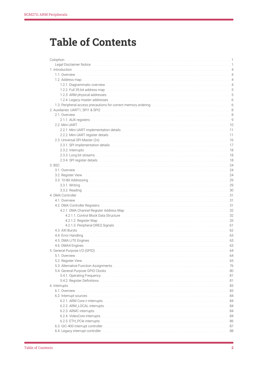
BCM2711 ARM Peripherals Table of Contents Colophon. . . . . . . . . . . . . . . . . . . . . . . . . . . . . . . . . . . . . . . . . . . . . . . . . . . . . . . . . . . . . . . . . . . . . . . . . . . . . . . . . . . . . . . . . . . . . . . . . . . .  1 Legal Disclaimer Notice . . . . . . . . . . . . . . . . . . . . . . . . . . . . . . . . . . . . . . . . . . . . . . . . . . . . . . . . . . . . . . . . . . . . . . . . . . . . . . . . . . . .  1 1. Introduction . . . . . . . . . . . . . . . . . . . . . . . . . . . . . . . . . . . . . . . . . . . . . . . . . . . . . . . . . . . . . . . . . . . . . . . . . . . . . . . . . . . . . . . . . . . . . . .  4 1.1. Overview . . . . . . . . . . . . . . . . . . . . . . . . . . . . . . . . . . . . . . . . . . . . . . . . . . . . . . . . . . . . . . . . . . . . . . . . . . . . . . . . . . . . . . . . . . . . .  4 1.2. Address map . . . . . . . . . . . . . . . . . . . . . . . . . . . . . . . . . . . . . . . . . . . . . . . . . . . . . . . . . . . . . . . . . . . . . . . . . . . . . . . . . . . . . . . . .  4 1.2.1. Diagrammatic overview . . . . . . . . . . . . . . . . . . . . . . . . . . . . . . . . . . . . . . . . . . . . . . . . . . . . . . . . . . . . . . . . . . . . . . . . . . .  4 1.2.2. Full 35-bit address map . . . . . . . . . . . . . . . . . . . . . . . . . . . . . . . . . . . . . . . . . . . . . . . . . . . . . . . . . . . . . . . . . . . . . . . . . . .  5 1.2.3. ARM physical addresses. . . . . . . . . . . . . . . . . . . . . . . . . . . . . . . . . . . . . . . . . . . . . . . . . . . . . . . . . . . . . . . . . . . . . . . . . . .  5 1.2.4. Legacy master addresses . . . . . . . . . . . . . . . . . . . . . . . . . . . . . . . . . . . . . . . . . . . . . . . . . . . . . . . . . . . . . . . . . . . . . . . . .  6 1.3. Peripheral access precautions for correct memory ordering . . . . . . . . . . . . . . . . . . . . . . . . . . . . . . . . . . . . . . . . . . . . . . . .  6 2. Auxiliaries: UART1, SPI1 & SPI2 . . . . . . . . . . . . . . . . . . . . . . . . . . . . . . . . . . . . . . . . . . . . . . . . . . . . . . . . . . . . . . . . . . . . . . . . . . . . . .  8 2.1. Overview . . . . . . . . . . . . . . . . . . . . . . . . . . . . . . . . . . . . . . . . . . . . . . . . . . . . . . . . . . . . . . . . . . . . . . . . . . . . . . . . . . . . . . . . . . . . .  8 2.1.1. AUX registers . . . . . . . . . . . . . . . . . . . . . . . . . . . . . . . . . . . . . . . . . . . . . . . . . . . . . . . . . . . . . . . . . . . . . . . . . . . . . . . . . . . .  9 2.2. Mini UART . . . . . . . . . . . . . . . . . . . . . . . . . . . . . . . . . . . . . . . . . . . . . . . . . . . . . . . . . . . . . . . . . . . . . . . . . . . . . . . . . . . . . . . . . . .  10 2.2.1. Mini UART implementation details . . . . . . . . . . . . . . . . . . . . . . . . . . . . . . . . . . . . . . . . . . . . . . . . . . . . . . . . . . . . . . . . .  11 2.2.2. Mini UART register details . . . . . . . . . . . . . . . . . . . . . . . . . . . . . . . . . . . . . . . . . . . . . . . . . . . . . . . . . . . . . . . . . . . . . . . .  11 2.3. Universal SPI Master (2x). . . . . . . . . . . . . . . . . . . . . . . . . . . . . . . . . . . . . . . . . . . . . . . . . . . . . . . . . . . . . . . . . . . . . . . . . . . . . .  16 2.3.1. SPI implementation details . . . . . . . . . . . . . . . . . . . . . . . . . . . . . . . . . . . . . . . . . . . . . . . . . . . . . . . . . . . . . . . . . . . . . . .  17 2.3.2. Interrupts . . . . . . . . . . . . . . . . . . . . . . . . . . . . . . . . . . . . . . . . . . . . . . . . . . . . . . . . . . . . . . . . . . . . . . . . . . . . . . . . . . . . . . .  18 2.3.3. Long bit streams . . . . . . . . . . . . . . . . . . . . . . . . . . . . . . . . . . . . . . . . . . . . . . . . . . . . . . . . . . . . . . . . . . . . . . . . . . . . . . . .  18 2.3.4. SPI register details. . . . . . . . . . . . . . . . . . . . . . . . . . . . . . . . . . . . . . . . . . . . . . . . . . . . . . . . . . . . . . . . . . . . . . . . . . . . . . .  18 3. BSC . . . . . . . . . . . . . . . . . . . . . . . . . . . . . . . . . . . . . . . . . . . . . . . . . . . . . . . . . . . . . . . . . . . . . . . . . . . . . . . . . . . . . . . . . . . . . . . . . . . . .  24 3.1. Overview . . . . . . . . . . . . . . . . . . . . . . . . . . . . . . . . . . . . . . . . . . . . . . . . . . . . . . . . . . . . . . . . . . . . . . . . . . . . . . . . . . . . . . . . . . . .  24 3.2. Register View . . . . . . . . . . . . . . . . . . . . . . . . . . . . . . . . . . . . . . . . . . . . . . . . . . . . . . . . . . . . . . . . . . . . . . . . . . . . . . . . . . . . . . . .  24 3.3. 10-Bit Addressing . . . . . . . . . . . . . . . . . . . . . . . . . . . . . . . . . . . . . . . . . . . . . . . . . . . . . . . . . . . . . . . . . . . . . . . . . . . . . . . . . . . .  29 3.3.1. Writing . . . . . . . . . . . . . . . . . . . . . . . . . . . . . . . . . . . . . . . . . . . . . . . . . . . . . . . . . . . . . . . . . . . . . . . . . . . . . . . . . . . . . . . . .  29 3.3.2. Reading . . . . . . . . . . . . . . . . . . . . . . . . . . . . . . . . . . . . . . . . . . . . . . . . . . . . . . . . . . . . . . . . . . . . . . . . . . . . . . . . . . . . . . . .  30 4. DMA Controller . . . . . . . . . . . . . . . . . . . . . . . . . . . . . . . . . . . . . . . . . . . . . . . . . . . . . . . . . . . . . . . . . . . . . . . . . . . . . . . . . . . . . . . . . . .  31 4.1. Overview . . . . . . . . . . . . . . . . . . . . . . . . . . . . . . . . . . . . . . . . . . . . . . . . . . . . . . . . . . . . . . . . . . . . . . . . . . . . . . . . . . . . . . . . . . . .  31 4.2. DMA Controller Registers. . . . . . . . . . . . . . . . . . . . . . . . . . . . . . . . . . . . . . . . . . . . . . . . . . . . . . . . . . . . . . . . . . . . . . . . . . . . . .  31 4.2.1. DMA Channel Register Address Map. . . . . . . . . . . . . . . . . . . . . . . . . . . . . . . . . . . . . . . . . . . . . . . . . . . . . . . . . . . . . . .  32 4.2.1.1. Control Block Data Structure . . . . . . . . . . . . . . . . . . . . . . . . . . . . . . . . . . . . . . . . . . . . . . . . . . . . . . . . . . . . . . . . .  32 4.2.1.2. Register Map . . . . . . . . . . . . . . . . . . . . . . . . . . . . . . . . . . . . . . . . . . . . . . . . . . . . . . . . . . . . . . . . . . . . . . . . . . . . . . .  33 4.2.1.3. Peripheral DREQ Signals . . . . . . . . . . . . . . . . . . . . . . . . . . . . . . . . . . . . . . . . . . . . . . . . . . . . . . . . . . . . . . . . . . . . .  61 4.3. AXI Bursts . . . . . . . . . . . . . . . . . . . . . . . . . . . . . . . . . . . . . . . . . . . . . . . . . . . . . . . . . . . . . . . . . . . . . . . . . . . . . . . . . . . . . . . . . . .  62 4.4. Error Handling . . . . . . . . . . . . . . . . . . . . . . . . . . . . . . . . . . . . . . . . . . . . . . . . . . . . . . . . . . . . . . . . . . . . . . . . . . . . . . . . . . . . . . .  63 4.5. DMA LITE Engines. . . . . . . . . . . . . . . . . . . . . . . . . . . . . . . . . . . . . . . . . . . . . . . . . . . . . . . . . . . . . . . . . . . . . . . . . . . . . . . . . . . .  63 4.6. DMA4 Engines . . . . . . . . . . . . . . . . . . . . . . . . . . . . . . . . . . . . . . . . . . . . . . . . . . . . . . . . . . . . . . . . . . . . . . . . . . . . . . . . . . . . . . .  63 5. General Purpose I/O (GPIO) . . . . . . . . . . . . . . . . . . . . . . . . . . . . . . . . . . . . . . . . . . . . . . . . . . . . . . . . . . . . . . . . . . . . . . . . . . . . . . . .  64 5.1. Overview . . . . . . . . . . . . . . . . . . . . . . . . . . . . . . . . . . . . . . . . . . . . . . . . . . . . . . . . . . . . . . . . . . . . . . . . . . . . . . . . . . . . . . . . . . . .  64 5.2. Register View . . . . . . . . . . . . . . . . . . . . . . . . . . . . . . . . . . . . . . . . . . . . . . . . . . . . . . . . . . . . . . . . . . . . . . . . . . . . . . . . . . . . . . . .  65 5.3. Alternative Function Assignments . . . . . . . . . . . . . . . . . . . . . . . . . . . . . . . . . . . . . . . . . . . . . . . . . . . . . . . . . . . . . . . . . . . . . .  76 5.4. General Purpose GPIO Clocks. . . . . . . . . . . . . . . . . . . . . . . . . . . . . . . . . . . . . . . . . . . . . . . . . . . . . . . . . . . . . . . . . . . . . . . . . .  80 5.4.1. Operating Frequency. . . . . . . . . . . . . . . . . . . . . . . . . . . . . . . . . . . . . . . . . . . . . . . . . . . . . . . . . . . . . . . . . . . . . . . . . . . . .  81 5.4.2. Register Definitions . . . . . . . . . . . . . . . . . . . . . . . . . . . . . . . . . . . . . . . . . . . . . . . . . . . . . . . . . . . . . . . . . . . . . . . . . . . . . .  81 6. Interrupts . . . . . . . . . . . . . . . . . . . . . . . . . . . . . . . . . . . . . . . . . . . . . . . . . . . . . . . . . . . . . . . . . . . . . . . . . . . . . . . . . . . . . . . . . . . . . . . .  83 6.1. Overview . . . . . . . . . . . . . . . . . . . . . . . . . . . . . . . . . . . . . . . . . . . . . . . . . . . . . . . . . . . . . . . . . . . . . . . . . . . . . . . . . . . . . . . . . . . .  83 6.2. Interrupt sources . . . . . . . . . . . . . . . . . . . . . . . . . . . . . . . . . . . . . . . . . . . . . . . . . . . . . . . . . . . . . . . . . . . . . . . . . . . . . . . . . . . . .  84 6.2.1. ARM Core n interrupts. . . . . . . . . . . . . . . . . . . . . . . . . . . . . . . . . . . . . . . . . . . . . . . . . . . . . . . . . . . . . . . . . . . . . . . . . . . .  84 6.2.2. ARM_LOCAL interrupts . . . . . . . . . . . . . . . . . . . . . . . . . . . . . . . . . . . . . . . . . . . . . . . . . . . . . . . . . . . . . . . . . . . . . . . . . . .  84 6.2.3. ARMC interrupts. . . . . . . . . . . . . . . . . . . . . . . . . . . . . . . . . . . . . . . . . . . . . . . . . . . . . . . . . . . . . . . . . . . . . . . . . . . . . . . . .  84 6.2.4. VideoCore interrupts . . . . . . . . . . . . . . . . . . . . . . . . . . . . . . . . . . . . . . . . . . . . . . . . . . . . . . . . . . . . . . . . . . . . . . . . . . . . .  84 6.2.5. ETH_PCIe interrupts . . . . . . . . . . . . . . . . . . . . . . . . . . . . . . . . . . . . . . . . . . . . . . . . . . . . . . . . . . . . . . . . . . . . . . . . . . . . .  86 6.3. GIC-400 interrupt controller. . . . . . . . . . . . . . . . . . . . . . . . . . . . . . . . . . . . . . . . . . . . . . . . . . . . . . . . . . . . . . . . . . . . . . . . . . . .  87 6.4. Legacy interrupt controller. . . . . . . . . . . . . . . . . . . . . . . . . . . . . . . . . . . . . . . . . . . . . . . . . . . . . . . . . . . . . . . . . . . . . . . . . . . . .  88 Table of Contents 2
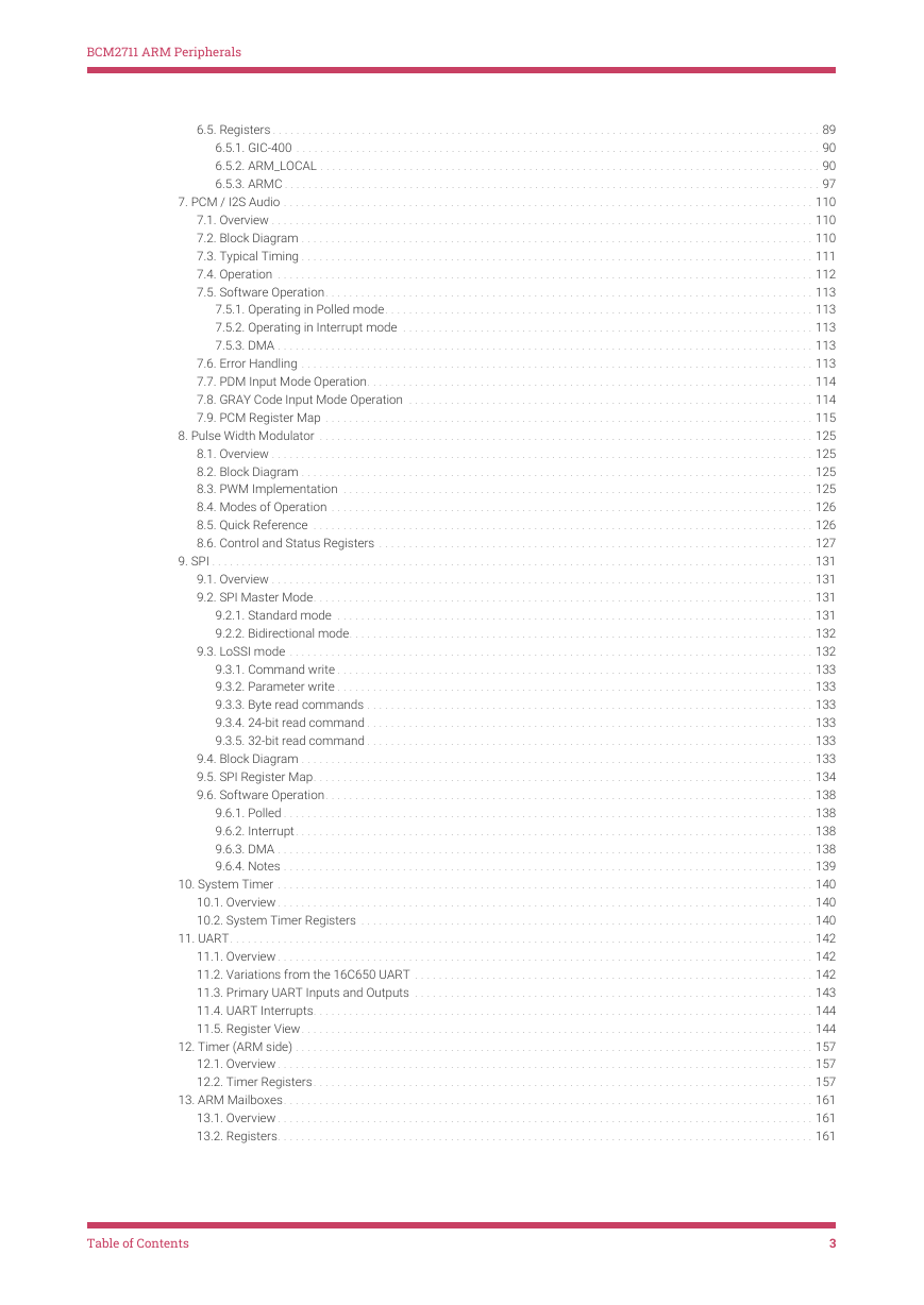
BCM2711 ARM Peripherals 6.5. Registers . . . . . . . . . . . . . . . . . . . . . . . . . . . . . . . . . . . . . . . . . . . . . . . . . . . . . . . . . . . . . . . . . . . . . . . . . . . . . . . . . . . . . . . . . . . .  89 6.5.1. GIC-400 . . . . . . . . . . . . . . . . . . . . . . . . . . . . . . . . . . . . . . . . . . . . . . . . . . . . . . . . . . . . . . . . . . . . . . . . . . . . . . . . . . . . . . . .  90 6.5.2. ARM_LOCAL . . . . . . . . . . . . . . . . . . . . . . . . . . . . . . . . . . . . . . . . . . . . . . . . . . . . . . . . . . . . . . . . . . . . . . . . . . . . . . . . . . . .  90 6.5.3. ARMC . . . . . . . . . . . . . . . . . . . . . . . . . . . . . . . . . . . . . . . . . . . . . . . . . . . . . . . . . . . . . . . . . . . . . . . . . . . . . . . . . . . . . . . . . .  97 7. PCM / I2S Audio . . . . . . . . . . . . . . . . . . . . . . . . . . . . . . . . . . . . . . . . . . . . . . . . . . . . . . . . . . . . . . . . . . . . . . . . . . . . . . . . . . . . . . . . .  110 7.1. Overview . . . . . . . . . . . . . . . . . . . . . . . . . . . . . . . . . . . . . . . . . . . . . . . . . . . . . . . . . . . . . . . . . . . . . . . . . . . . . . . . . . . . . . . . . . .  110 7.2. Block Diagram . . . . . . . . . . . . . . . . . . . . . . . . . . . . . . . . . . . . . . . . . . . . . . . . . . . . . . . . . . . . . . . . . . . . . . . . . . . . . . . . . . . . . .  110 7.3. Typical Timing . . . . . . . . . . . . . . . . . . . . . . . . . . . . . . . . . . . . . . . . . . . . . . . . . . . . . . . . . . . . . . . . . . . . . . . . . . . . . . . . . . . . . .  111 7.4. Operation . . . . . . . . . . . . . . . . . . . . . . . . . . . . . . . . . . . . . . . . . . . . . . . . . . . . . . . . . . . . . . . . . . . . . . . . . . . . . . . . . . . . . . . . . .  112 7.5. Software Operation. . . . . . . . . . . . . . . . . . . . . . . . . . . . . . . . . . . . . . . . . . . . . . . . . . . . . . . . . . . . . . . . . . . . . . . . . . . . . . . . . .  113 7.5.1. Operating in Polled mode. . . . . . . . . . . . . . . . . . . . . . . . . . . . . . . . . . . . . . . . . . . . . . . . . . . . . . . . . . . . . . . . . . . . . . . .  113 7.5.2. Operating in Interrupt mode . . . . . . . . . . . . . . . . . . . . . . . . . . . . . . . . . . . . . . . . . . . . . . . . . . . . . . . . . . . . . . . . . . . . .  113 7.5.3. DMA . . . . . . . . . . . . . . . . . . . . . . . . . . . . . . . . . . . . . . . . . . . . . . . . . . . . . . . . . . . . . . . . . . . . . . . . . . . . . . . . . . . . . . . . . .  113 7.6. Error Handling . . . . . . . . . . . . . . . . . . . . . . . . . . . . . . . . . . . . . . . . . . . . . . . . . . . . . . . . . . . . . . . . . . . . . . . . . . . . . . . . . . . . . .  113 7.7. PDM Input Mode Operation. . . . . . . . . . . . . . . . . . . . . . . . . . . . . . . . . . . . . . . . . . . . . . . . . . . . . . . . . . . . . . . . . . . . . . . . . . .  114 7.8. GRAY Code Input Mode Operation . . . . . . . . . . . . . . . . . . . . . . . . . . . . . . . . . . . . . . . . . . . . . . . . . . . . . . . . . . . . . . . . . . . .  114 7.9. PCM Register Map . . . . . . . . . . . . . . . . . . . . . . . . . . . . . . . . . . . . . . . . . . . . . . . . . . . . . . . . . . . . . . . . . . . . . . . . . . . . . . . . . .  115 8. Pulse Width Modulator . . . . . . . . . . . . . . . . . . . . . . . . . . . . . . . . . . . . . . . . . . . . . . . . . . . . . . . . . . . . . . . . . . . . . . . . . . . . . . . . . . .  125 8.1. Overview . . . . . . . . . . . . . . . . . . . . . . . . . . . . . . . . . . . . . . . . . . . . . . . . . . . . . . . . . . . . . . . . . . . . . . . . . . . . . . . . . . . . . . . . . . .  125 8.2. Block Diagram . . . . . . . . . . . . . . . . . . . . . . . . . . . . . . . . . . . . . . . . . . . . . . . . . . . . . . . . . . . . . . . . . . . . . . . . . . . . . . . . . . . . . .  125 8.3. PWM Implementation . . . . . . . . . . . . . . . . . . . . . . . . . . . . . . . . . . . . . . . . . . . . . . . . . . . . . . . . . . . . . . . . . . . . . . . . . . . . . . .  125 8.4. Modes of Operation . . . . . . . . . . . . . . . . . . . . . . . . . . . . . . . . . . . . . . . . . . . . . . . . . . . . . . . . . . . . . . . . . . . . . . . . . . . . . . . . .  126 8.5. Quick Reference . . . . . . . . . . . . . . . . . . . . . . . . . . . . . . . . . . . . . . . . . . . . . . . . . . . . . . . . . . . . . . . . . . . . . . . . . . . . . . . . . . . .  126 8.6. Control and Status Registers . . . . . . . . . . . . . . . . . . . . . . . . . . . . . . . . . . . . . . . . . . . . . . . . . . . . . . . . . . . . . . . . . . . . . . . . .  127 9. SPI . . . . . . . . . . . . . . . . . . . . . . . . . . . . . . . . . . . . . . . . . . . . . . . . . . . . . . . . . . . . . . . . . . . . . . . . . . . . . . . . . . . . . . . . . . . . . . . . . . . . .  131 9.1. Overview . . . . . . . . . . . . . . . . . . . . . . . . . . . . . . . . . . . . . . . . . . . . . . . . . . . . . . . . . . . . . . . . . . . . . . . . . . . . . . . . . . . . . . . . . . .  131 9.2. SPI Master Mode. . . . . . . . . . . . . . . . . . . . . . . . . . . . . . . . . . . . . . . . . . . . . . . . . . . . . . . . . . . . . . . . . . . . . . . . . . . . . . . . . . . .  131 9.2.1. Standard mode . . . . . . . . . . . . . . . . . . . . . . . . . . . . . . . . . . . . . . . . . . . . . . . . . . . . . . . . . . . . . . . . . . . . . . . . . . . . . . . .  131 9.2.2. Bidirectional mode. . . . . . . . . . . . . . . . . . . . . . . . . . . . . . . . . . . . . . . . . . . . . . . . . . . . . . . . . . . . . . . . . . . . . . . . . . . . . .  132 9.3. LoSSI mode . . . . . . . . . . . . . . . . . . . . . . . . . . . . . . . . . . . . . . . . . . . . . . . . . . . . . . . . . . . . . . . . . . . . . . . . . . . . . . . . . . . . . . . .  132 9.3.1. Command write . . . . . . . . . . . . . . . . . . . . . . . . . . . . . . . . . . . . . . . . . . . . . . . . . . . . . . . . . . . . . . . . . . . . . . . . . . . . . . . .  133 9.3.2. Parameter write . . . . . . . . . . . . . . . . . . . . . . . . . . . . . . . . . . . . . . . . . . . . . . . . . . . . . . . . . . . . . . . . . . . . . . . . . . . . . . . .  133 9.3.3. Byte read commands . . . . . . . . . . . . . . . . . . . . . . . . . . . . . . . . . . . . . . . . . . . . . . . . . . . . . . . . . . . . . . . . . . . . . . . . . . .  133 9.3.4. 24-bit read command . . . . . . . . . . . . . . . . . . . . . . . . . . . . . . . . . . . . . . . . . . . . . . . . . . . . . . . . . . . . . . . . . . . . . . . . . . .  133 9.3.5. 32-bit read command . . . . . . . . . . . . . . . . . . . . . . . . . . . . . . . . . . . . . . . . . . . . . . . . . . . . . . . . . . . . . . . . . . . . . . . . . . .  133 9.4. Block Diagram . . . . . . . . . . . . . . . . . . . . . . . . . . . . . . . . . . . . . . . . . . . . . . . . . . . . . . . . . . . . . . . . . . . . . . . . . . . . . . . . . . . . . .  133 9.5. SPI Register Map. . . . . . . . . . . . . . . . . . . . . . . . . . . . . . . . . . . . . . . . . . . . . . . . . . . . . . . . . . . . . . . . . . . . . . . . . . . . . . . . . . . .  134 9.6. Software Operation. . . . . . . . . . . . . . . . . . . . . . . . . . . . . . . . . . . . . . . . . . . . . . . . . . . . . . . . . . . . . . . . . . . . . . . . . . . . . . . . . .  138 9.6.1. Polled . . . . . . . . . . . . . . . . . . . . . . . . . . . . . . . . . . . . . . . . . . . . . . . . . . . . . . . . . . . . . . . . . . . . . . . . . . . . . . . . . . . . . . . . .  138 9.6.2. Interrupt. . . . . . . . . . . . . . . . . . . . . . . . . . . . . . . . . . . . . . . . . . . . . . . . . . . . . . . . . . . . . . . . . . . . . . . . . . . . . . . . . . . . . . .  138 9.6.3. DMA . . . . . . . . . . . . . . . . . . . . . . . . . . . . . . . . . . . . . . . . . . . . . . . . . . . . . . . . . . . . . . . . . . . . . . . . . . . . . . . . . . . . . . . . . .  138 9.6.4. Notes . . . . . . . . . . . . . . . . . . . . . . . . . . . . . . . . . . . . . . . . . . . . . . . . . . . . . . . . . . . . . . . . . . . . . . . . . . . . . . . . . . . . . . . . .  139 10. System Timer . . . . . . . . . . . . . . . . . . . . . . . . . . . . . . . . . . . . . . . . . . . . . . . . . . . . . . . . . . . . . . . . . . . . . . . . . . . . . . . . . . . . . . . . . .  140 10.1. Overview . . . . . . . . . . . . . . . . . . . . . . . . . . . . . . . . . . . . . . . . . . . . . . . . . . . . . . . . . . . . . . . . . . . . . . . . . . . . . . . . . . . . . . . . . .  140 10.2. System Timer Registers . . . . . . . . . . . . . . . . . . . . . . . . . . . . . . . . . . . . . . . . . . . . . . . . . . . . . . . . . . . . . . . . . . . . . . . . . . . .  140 11. UART. . . . . . . . . . . . . . . . . . . . . . . . . . . . . . . . . . . . . . . . . . . . . . . . . . . . . . . . . . . . . . . . . . . . . . . . . . . . . . . . . . . . . . . . . . . . . . . . . .  142 11.1. Overview . . . . . . . . . . . . . . . . . . . . . . . . . . . . . . . . . . . . . . . . . . . . . . . . . . . . . . . . . . . . . . . . . . . . . . . . . . . . . . . . . . . . . . . . . .  142 11.2. Variations from the 16C650 UART . . . . . . . . . . . . . . . . . . . . . . . . . . . . . . . . . . . . . . . . . . . . . . . . . . . . . . . . . . . . . . . . . . .  142 11.3. Primary UART Inputs and Outputs . . . . . . . . . . . . . . . . . . . . . . . . . . . . . . . . . . . . . . . . . . . . . . . . . . . . . . . . . . . . . . . . . . .  143 11.4. UART Interrupts. . . . . . . . . . . . . . . . . . . . . . . . . . . . . . . . . . . . . . . . . . . . . . . . . . . . . . . . . . . . . . . . . . . . . . . . . . . . . . . . . . . .  144 11.5. Register View. . . . . . . . . . . . . . . . . . . . . . . . . . . . . . . . . . . . . . . . . . . . . . . . . . . . . . . . . . . . . . . . . . . . . . . . . . . . . . . . . . . . . .  144 12. Timer (ARM side) . . . . . . . . . . . . . . . . . . . . . . . . . . . . . . . . . . . . . . . . . . . . . . . . . . . . . . . . . . . . . . . . . . . . . . . . . . . . . . . . . . . . . . .  157 12.1. Overview . . . . . . . . . . . . . . . . . . . . . . . . . . . . . . . . . . . . . . . . . . . . . . . . . . . . . . . . . . . . . . . . . . . . . . . . . . . . . . . . . . . . . . . . . .  157 12.2. Timer Registers. . . . . . . . . . . . . . . . . . . . . . . . . . . . . . . . . . . . . . . . . . . . . . . . . . . . . . . . . . . . . . . . . . . . . . . . . . . . . . . . . . . .  157 13. ARM Mailboxes. . . . . . . . . . . . . . . . . . . . . . . . . . . . . . . . . . . . . . . . . . . . . . . . . . . . . . . . . . . . . . . . . . . . . . . . . . . . . . . . . . . . . . . . .  161 13.1. Overview . . . . . . . . . . . . . . . . . . . . . . . . . . . . . . . . . . . . . . . . . . . . . . . . . . . . . . . . . . . . . . . . . . . . . . . . . . . . . . . . . . . . . . . . . .  161 13.2. Registers. . . . . . . . . . . . . . . . . . . . . . . . . . . . . . . . . . . . . . . . . . . . . . . . . . . . . . . . . . . . . . . . . . . . . . . . . . . . . . . . . . . . . . . . . .  161 Table of Contents 3
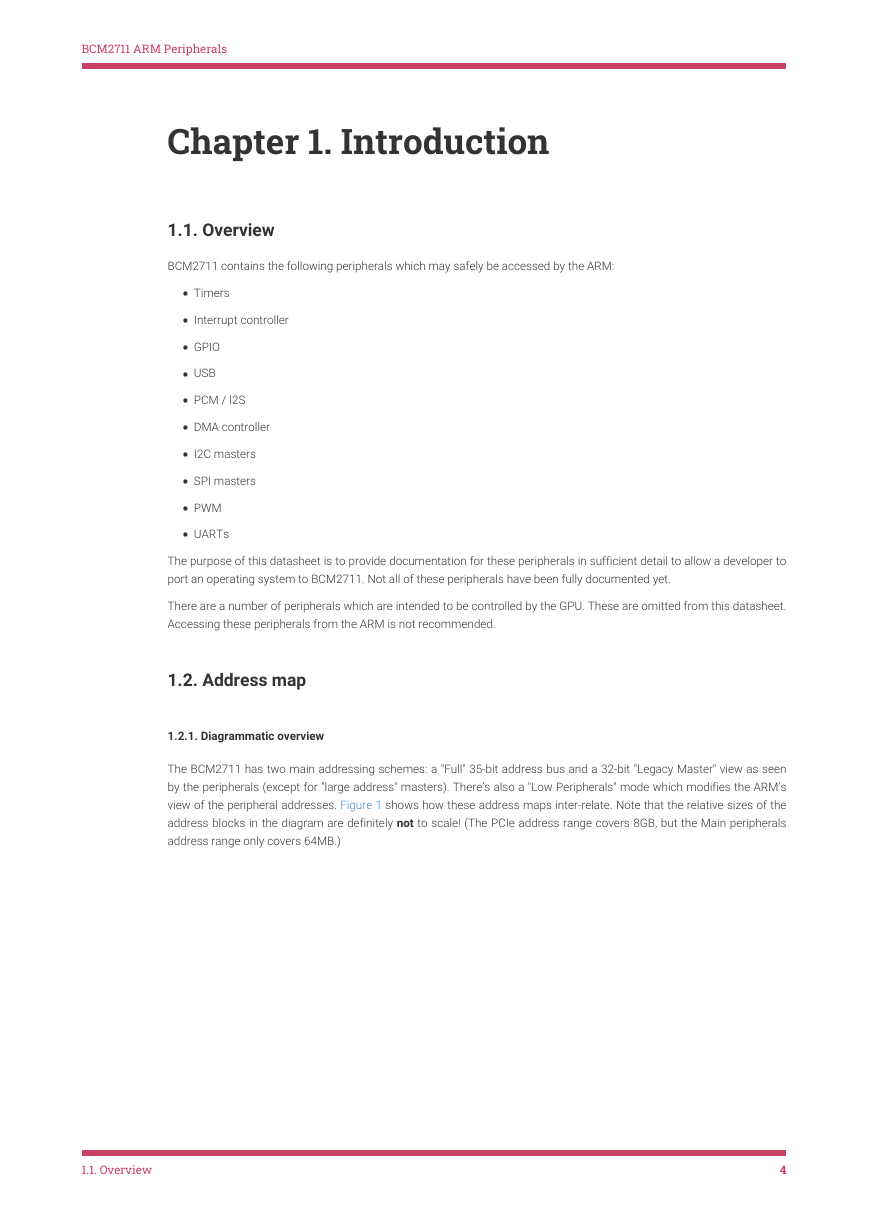
BCM2711 ARM Peripherals Chapter 1. Introduction 1.1. Overview BCM2711 contains the following peripherals which may safely be accessed by the ARM: • Timers • Interrupt controller • GPIO • USB • PCM / I2S • DMA controller • I2C masters • SPI masters • PWM • UARTs The purpose of this datasheet is to provide documentation for these peripherals in sufficient detail to allow a developer to port an operating system to BCM2711. Not all of these peripherals have been fully documented yet. There are a number of peripherals which are intended to be controlled by the GPU. These are omitted from this datasheet. Accessing these peripherals from the ARM is not recommended. 1.2. Address map 1.2.1. Diagrammatic overview The BCM2711 has two main addressing schemes: a "Full" 35-bit address bus and a 32-bit "Legacy Master" view as seen by the peripherals (except for "large address" masters). There’s also a "Low Peripherals" mode which modifies the ARM’s view of the peripheral addresses. Figure 1 shows how these address maps inter-relate. Note that the relative sizes of the address blocks in the diagram are definitely not to scale! (The PCIe address range covers 8GB, but the Main peripherals address range only covers 64MB.) 1.1. Overview 4
BCM2711 ARM Peripherals Figure 1. BCM2711 Address Maps SDRAM (for the ARM) L2 Cached (non-allocating) Main peripherals Reserved L2 Cached (allocating) 0xFFFF_FFFF 0xC000_0000 Paging registers 0x8000_0000 0x7c00_0000 0x4000_0000 0x0000_0000 PCIe Reserved ARM Local peripherals L2 Cached (non-allocating) Main peripherals Reserved L2 Cached (allocating) SDRAM (for the ARM) SDRAM (for the VC) SDRAM (for the ARM) 0x7_FFFF_FFFF 0x6_0000_0000 0x5_0000_0000 0x7_FFFF_FFFF 0x6_0000_0000 PCIe Reserved 0x4_C000_0000 0x4_C000_0000 0x4_8000_0000 0x4_7C00_0000 L2 Cached (non-allocating) Reserved 0x4_8000_0000 0x4_4000_0000 0x4_4000_0000 0x4_0000_0000 0x0_4000_0000 Size of VC SDRAM determined by config.txt 0x0_0000_0000 L2 Cached (allocating) SDRAM (for the ARM) ARM Local peripherals Main peripherals SDRAM (for the ARM) SDRAM (for the VC) SDRAM (for the ARM) 0x4_0000_0000 0x1_0000_0000 0x0_FF80_0000 0x0_FC00_0000 0x0_4000_0000 0x0_0000_0000 Legacy Master view of Address Map Full 35-bit Address Map ARM view of the Address Map in “Low Peripheral” mode Addresses in ARM Linux are: 1. Issued as virtual addresses by the ARM core, then 2. Mapped into a physical address by the ARM MMU, then 3. Used to select the appropriate peripheral or location in RAM 1.2.2. Full 35-bit address map The full 35-bit address map is shown in Figure 1. This is seen by both "large address" masters (e.g. the DMA4 engines) and the ARM CPU. It has two L2 cache aliases (one allocating, one non-allocating) which cache (only) the first 1GB of SDRAM. 1.2.3. ARM physical addresses Physical addresses start at 0x0_0000_0000 for RAM. • The ARM section of the RAM starts at 0x0_0000_0000 and extends up to the size of installed SDRAM. • The VideoCore section of the RAM is mapped in from 0x0_4000_0000 downwards. The size of the VideoCore RAM is determined by a setting in config.txt - refer to raspberrypi.org documentation for further details. The VideoCore maps the ARM physical address space directly to the bus address space seen by VideoCore. The bus addresses for RAM are set up to map onto the uncached bus address range on the VideoCore starting at 0x0_0000_0000. 1.2. Address map 5
BCM2711 ARM Peripherals  NOTE BCM2711 provides a 1MB system L2 cache, which is used primarily by the GPU. Accesses to memory are routed either via or around the L2 cache depending on the address range being used. When running in 32-bit mode, the ARM uses LPAE mode to enable it to access the full 32GB address space. Physical addresses range from 0x4_7C00_0000 to 0x4_7FFF_FFFF for Main peripherals, and from 0x4_C000_0000 to 0x4_FFFF_FFFF for ARM Local peripherals. If the VPU enables "Low Peripheral" mode then the ARM (only) has Main peripherals available from 0x0_FC00_0000 to 0x0_FF7F_FFFF and ARM Local peripherals available from 0x0_FF80_0000 to 0x0_FFFF_FFFF. 1.2.4. Legacy master addresses The peripheral addresses specified in this document are legacy master addresses. Software accessing peripherals using the DMA engines must use 32-bit legacy master addresses. The Main peripherals are available from 0x7C00_0000 to 0x7FFF_FFFF. Behind the scenes, the VideoCore transparently translates these addresses to the 35-bit 0x4_7nnn_nnnn addresses. So a peripheral described in this document as being at legacy address 0x7Enn_nnnn is available in the 35-bit address space at 0x4_7Enn_nnnn, and visible to the ARM at 0x0_FEnn_nnnn if Low Peripheral mode is enabled. Software accessing RAM using the DMA engines must use legacy addresses (between 0xC000_0000 and 0xFFFF_FFFF). This accesses a 1GB window within the full 16GB SDRAM address space. If the DMA engine needs to access RAM above the first 1GB, this window can be moved using the PAGE or PAGELITE bits - see Chapter 4 for more details. Behind the scenes, the VideoCore transparently translates these addresses to the 35-bit 0x0_nnnn_nnnn addresses. Software accessing the VPU L2 cache using the DMA engines must use legacy addresses starting at 0x0000_0000 (for allocating cache) or 0x8000_0000 (for non-allocating cache). Behind the scenes, the VideoCore transparently translates these addresses to the corresponding 35-bit 0x4_nnnn_nnnn addresses. These 1GB windows can’t be moved, and are limited to the first 1GB of SDRAM. 1.3. Peripheral access precautions for correct memory ordering The BCM2711 system uses an AMBA AXI-compatible interface structure. In order to keep the system complexity low and data throughput high, the BCM2711 AXI system does not always return read data in-order. The GPU has special logic to cope with data arriving out-of-order; however the ARM core does not contain such logic. Therefore some precautions must be taken when using the ARM to access peripherals. Accesses to the same peripheral will always arrive and return in-order. It is only when switching from one peripheral to another that data can arrive out-of-order. The simplest way to make sure that data is processed in-order is to place a memory barrier instruction at critical positions in the code. You should place: • A memory write barrier before the first write to a peripheral • A memory read barrier after the last read of a peripheral It is not required to put a memory barrier instruction after each read or write access. Only at those places in the code where it is possible that a peripheral read or write may be followed by a read or write of a different peripheral. This is normally at the entry and exit points of the peripheral service code. As interrupts can appear anywhere in the code, you should also safeguard those. If an interrupt routine reads from a peripheral the routine should start with a memory read barrier. If an interrupt routine writes to a peripheral the routine should end with a memory write barrier. 1.3. Peripheral access precautions for correct memory ordering 6
BCM2711 ARM Peripherals  NOTE Normally a processor assumes that if it executes two read operations the data will arrive in order. So a read from location X followed by a read from location Y should return the data of location X first, followed by the data of location Y. Data arriving out of order can have disastrous consequences. For example: a_status = *pointer_to_peripheral_a; b_status = *pointer_to_peripheral_b; Without precautions the values ending up in the variables a_status and b_status can be swapped around. It is theoretically possible for writes to go ‘wrong’ but that is far more difficult to achieve. The AXI system makes sure the data always arrives in-order at its intended destination. So: *pointer_to_peripheral_a = value_a; *pointer_to_peripheral_b = value_b; will always give the expected result. The only time write data can arrive out-of-order is if two different peripherals are connected to the same external equipment. 1.3. Peripheral access precautions for correct memory ordering 7
分享到:
收藏