Seepage Modeling
with SEEP/W
An Engineering Methodology
July 2012 Edition
GEO-SLOPE International Ltd.
�
Copyright © 2004-2012 by GEO-SLOPE International, Ltd.
All rights reserved. No part of this work may be reproduced or transmitted in any
form or by any means, electronic or mechanical, including photocopying,
recording, or by any information storage or retrieval system, without the prior
written permission of GEO-SLOPE International, Ltd.
Trademarks: GEO-SLOPE, GeoStudio, SLOPE/W, SEEP/W, SIGMA/W,
QUAKE/W, CTRAN/W, TEMP/W, AIR/W and VADOSE/W are trademarks or
registered trademarks of GEO-SLOPE International Ltd. in Canada and other
countries. Other trademarks are the property of their respective owners.
GEO-SLOPE International Ltd
1400, 633 – 6th Ave SW
Calgary, Alberta, Canada T2P 2Y5
E-mail: info@geo-slope.com
Web: http://www.geo-slope.com
�
SEEP/W
Table of Contents
Table of Contents
Introduction ......................................................................................... 1
1
2
3
2.5
How to model
Introduction
What is a numerical model?
Modeling in geotechnical engineering
Why model?
Numerical Modeling: What, Why and How ......................................... 3
3
2.1
2.2
3
5
2.3
2.4
7
Quantitative predictions ................................................................................................ 8
Compare alternatives ................................................................................................... 9
Identify governing parameters .................................................................................... 10
Discover & understand physical process - train our thinking ..................................... 11
14
Make a guess ............................................................................................................. 14
Simplify geometry ....................................................................................................... 16
Start simple ................................................................................................................. 17
Do numerical experiments .......................................................................................... 18
Model only essential components .............................................................................. 19
Start with estimated material properties ..................................................................... 20
Interrogate the results ................................................................................................. 21
Evaluate results in the context of expected results .................................................... 21
Remember the real world ........................................................................................... 21
2.6
22
2.7
23
Geometry and Meshing .................................................................... 25
25
3.1
3.2
26
Soil regions, points and lines ...................................................................................... 27
Free points .................................................................................................................. 29
Free lines .................................................................................................................... 29
Interface elements on lines ......................................................................................... 31
Circular openings ........................................................................................................ 33
34
Structured mesh ......................................................................................................... 35
Unstructured quad and triangle mesh ........................................................................ 35
Unstructured triangular mesh ..................................................................................... 35
Introduction
Geometry objects in GeoStudio
How not to model
Closing remarks
3.3
Mesh generation
Page i
�
Table of Contents
SEEP/W
Infinite regions
3.9
3.10 General guidelines for meshing
Surface layers
Joining regions
Meshing for transient analyses
Finite elements
Element fundamentals
Triangular grid regions ................................................................................................ 36
Rectangular grid of quads .......................................................................................... 37
37
40
41
42
43
Element nodes ............................................................................................................ 43
Field variable distribution ............................................................................................ 43
Element and mesh compatibility ................................................................................. 44
Numerical integration .................................................................................................. 46
Secondary variables ................................................................................................... 47
47
49
Number of elements ................................................................................................... 49
Effect of drawing scale ............................................................................................... 50
Mesh purpose ............................................................................................................. 50
Simplified geometry .................................................................................................... 52
Material Models and Properties ........................................................ 53
4.1
53
Material models in SEEP/W ....................................................................................... 53
54
Factors affecting the volumetric water content ........................................................... 56
56
Estimation method 1 (grain size - Modified Kovacs) .................................................. 57
Estimation method 2 (sample functions) .................................................................... 59
Closed form option 1 (Fredlund and Xing, 1994) ....................................................... 60
Closed form option 2 (Van Genuchten, 1980) ............................................................ 61
62
Direct measurement of water content function ........................................................... 62
63
64
66
68
Method 1 (Fredlund et al, 1994) ................................................................................. 68
Method 2 (Green and Corey, 1971) ........................................................................... 69
Coefficient of volume compressibility
Hydraulic conductivity
Frozen ground hydraulic conductivity
Conductivity function estimation methods
Storage function types and estimation methods
Soil water storage – water content function
Soil material function measurement
3.4
3.5
3.6
3.7
3.8
4.1
4.2
4.3
4.4
4.5
4.6
4.7
4
Soil behavior models
Page ii
�
SEEP/W
Table of Contents
4.8
4.9
5
6
5.4
Head boundary conditions
Introduction
Fundamentals
Boundary condition locations
Interface model parameters
Sensitivity of hydraulic results to material properties
Method 3 (Van Genuchten, 1980) .............................................................................. 70
71
72
Changes to the air-entry value (AEV) ......................................................................... 72
Changes to the saturated hydraulic conductivity ........................................................ 74
Changes to the slope of the VWC function ................................................................ 76
Changes to the residual volumetric water content ..................................................... 78
Boundary Conditions ........................................................................ 80
5.1
80
80
5.2
5.3
82
Region face boundary conditions ............................................................................... 83
83
Definition of total head ................................................................................................ 83
Head boundary conditions on a dam .......................................................................... 85
Constant pressure conditions ..................................................................................... 87
Far field head conditions ............................................................................................ 87
88
91
92
94
95
97
98
General ....................................................................................................................... 98
Head versus time ........................................................................................................ 99
Head versus volume ................................................................................................. 101
Nodal flux Q versus time .......................................................................................... 102
Unit flow rate versus time ......................................................................................... 103
Modifier function ....................................................................................................... 104
Analysis Types ................................................................................ 107
107
6.1
Boundary condition types in steady state ................................................................. 108
108
Initial conditions ........................................................................................................ 108
Drawing the initial water table .................................................................................. 110
Specified boundary flows
Sources and sinks
Seepage faces
Free drainage (unit gradient)
Ground surface infiltration and evaporation
Far field boundary conditions
Boundary functions
5.5
5.6
5.7
5.8
5.9
5.10
5.11
Steady state
6.2
Transient
Page iii
�
Table of Contents
SEEP/W
Spline functions
6.3
Time stepping - temporal integration
Staged / multiple analyses
Axisymmetric
Plan view (confined aquifer only)
Linear functions
Step functions
Closed form curve fits for water content functions
Add-in functions
Spatial functions
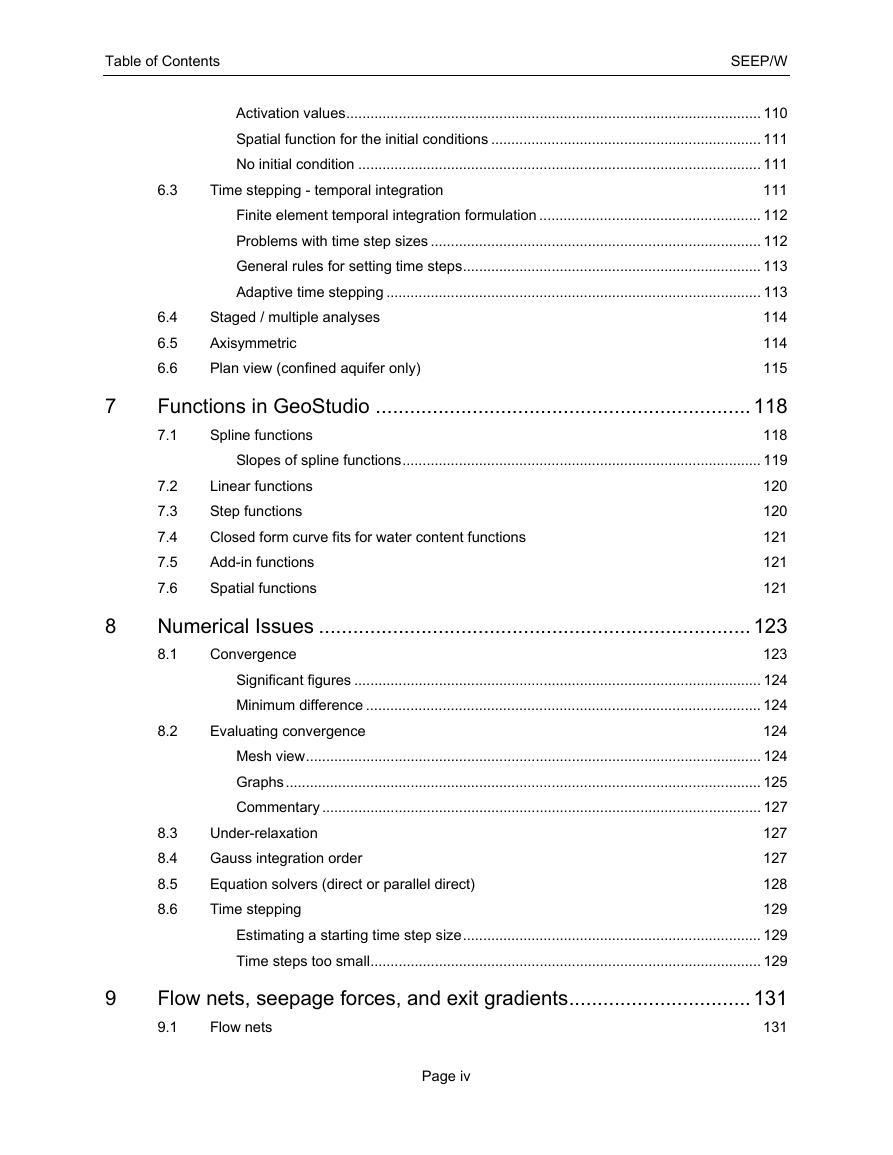
Activation values ....................................................................................................... 110
Spatial function for the initial conditions ................................................................... 111
No initial condition .................................................................................................... 111
111
Finite element temporal integration formulation ....................................................... 112
Problems with time step sizes .................................................................................. 112
General rules for setting time steps .......................................................................... 113
Adaptive time stepping ............................................................................................. 113
6.4
114
6.5
114
6.6
115
Functions in GeoStudio .................................................................. 118
118
7.1
Slopes of spline functions ......................................................................................... 119
7.2
120
7.3
120
7.4
121
7.5
121
7.6
121
Numerical Issues ............................................................................ 123
123
8.1
Significant figures ..................................................................................................... 124
Minimum difference .................................................................................................. 124
124
Mesh view ................................................................................................................. 124
Graphs ...................................................................................................................... 125
Commentary ............................................................................................................. 127
127
127
128
129
Estimating a starting time step size .......................................................................... 129
Time steps too small ................................................................................................. 129
Flow nets, seepage forces, and exit gradients ................................ 131
9.1
131
Under-relaxation
Gauss integration order
Equation solvers (direct or parallel direct)
Time stepping
Convergence
8.2
Evaluating convergence
7
8
9
8.3
8.4
8.5
8.6
Flow nets
Page iv
�
SEEP/W
Table of Contents
9.2
Seepage forces
9.3
Exit gradients
9.4
Concluding remarks
Transient versus steady state results
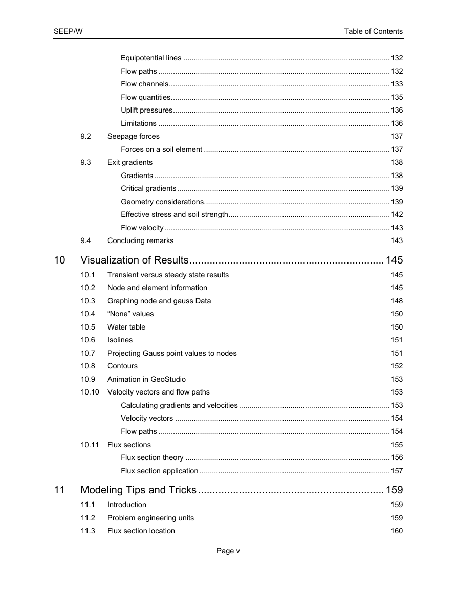
Equipotential lines .................................................................................................... 132
Flow paths ................................................................................................................ 132
Flow channels ........................................................................................................... 133
Flow quantities .......................................................................................................... 135
Uplift pressures ......................................................................................................... 136
Limitations ................................................................................................................ 136
137
Forces on a soil element .......................................................................................... 137
138
Gradients .................................................................................................................. 138
Critical gradients ....................................................................................................... 139
Geometry considerations .......................................................................................... 139
Effective stress and soil strength .............................................................................. 142
Flow velocity ............................................................................................................. 143
143
10 Visualization of Results ................................................................... 145
145
145
148
150
150
151
151
152
153
153
Calculating gradients and velocities ......................................................................... 153
Velocity vectors ........................................................................................................ 154
Flow paths ................................................................................................................ 154
155
Flux section theory ................................................................................................... 156
Flux section application ............................................................................................ 157
11 Modeling Tips and Tricks ................................................................ 159
159
159
160
10.1
10.2 Node and element information
10.3 Graphing node and gauss Data
10.4
10.5 Water table
10.6
10.7
10.8 Contours
10.9
10.10 Velocity vectors and flow paths
Introduction
Problem engineering units
Flux section location
Isolines
Projecting Gauss point values to nodes
“None” values
Animation in GeoStudio
10.11 Flux sections
11.1
11.2
11.3
Page v
�
Table of Contents
SEEP/W
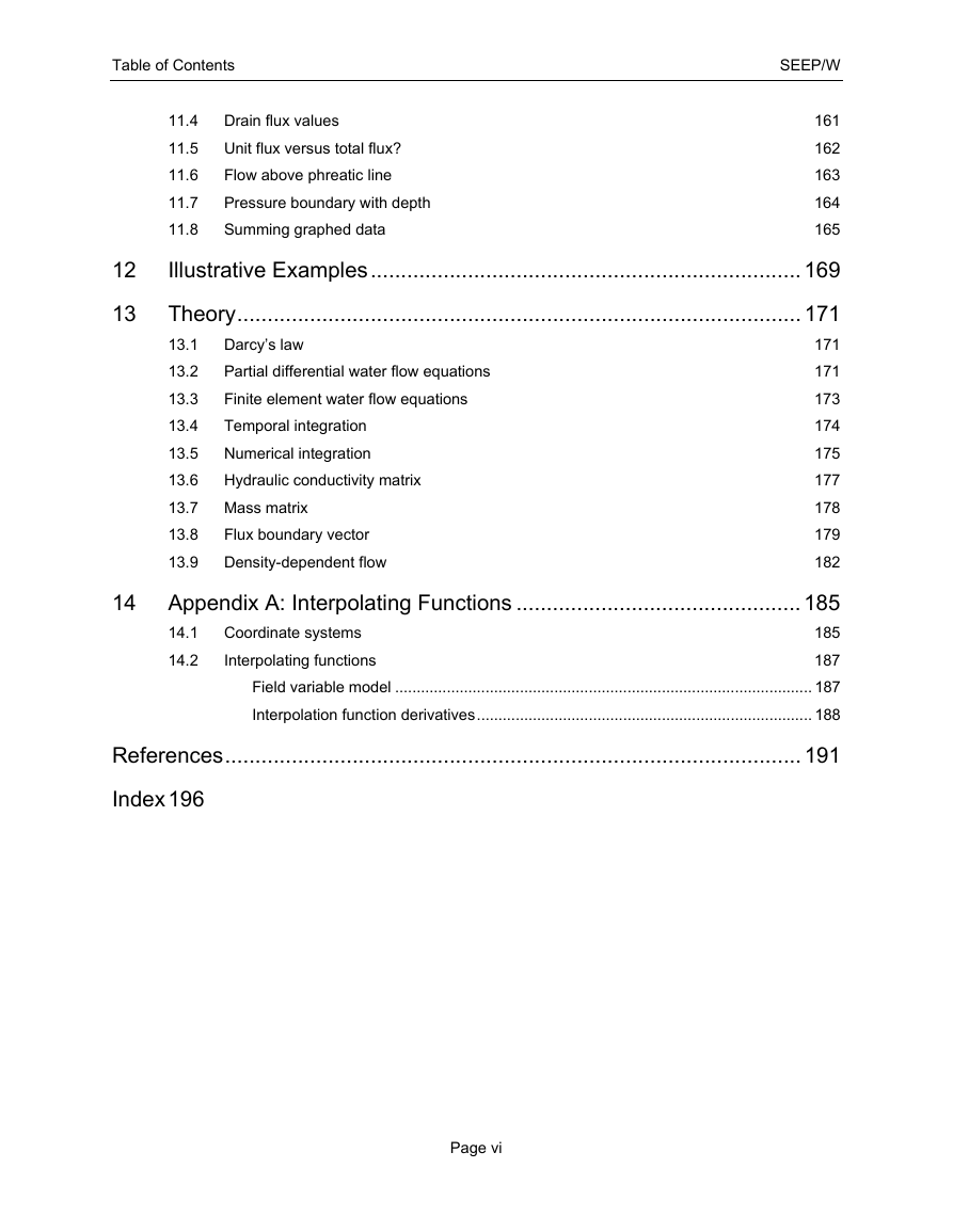
11.4 Drain flux values
161
11.5 Unit flux versus total flux?
162
Flow above phreatic line
11.6
163
11.7
Pressure boundary with depth
164
11.8
Summing graphed data
165
Illustrative Examples ....................................................................... 169
12
13
Theory ............................................................................................. 171
13.1 Darcy’s law
171
Partial differential water flow equations
171
13.2
173
Finite element water flow equations
13.3
Temporal integration
13.4
174
175
13.5 Numerical integration
177
13.6 Hydraulic conductivity matrix
13.7 Mass matrix
178
179
13.8
182
13.9 Density-dependent flow
14 Appendix A: Interpolating Functions ............................................... 185
185
187
Field variable model ................................................................................................. 187
Interpolation function derivatives .............................................................................. 188
References ............................................................................................... 191
14.1 Coordinate systems
14.2
Flux boundary vector
Interpolating functions
Index 196
Page vi
�



 2023年江西萍乡中考道德与法治真题及答案.doc
 2012年重庆南川中考生物真题及答案.doc
 2013年江西师范大学地理学综合及文艺理论基础考研真题.doc
 2020年四川甘孜小升初语文真题及答案I卷.doc
 2020年注册岩土工程师专业基础考试真题及答案.doc
 2023-2024学年福建省厦门市九年级上学期数学月考试题及答案.doc
 2021-2022学年辽宁省沈阳市大东区九年级上学期语文期末试题及答案.doc
 2022-2023学年北京东城区初三第一学期物理期末试卷及答案.doc
 2018上半年江西教师资格初中地理学科知识与教学能力真题及答案.doc
 2012年河北国家公务员申论考试真题及答案-省级.doc
 2020-2021学年江苏省扬州市江都区邵樊片九年级上学期数学第一次质量检测试题及答案.doc
 2022下半年黑龙江教师资格证中学综合素质真题及答案.doc