eCPRI Transport Network V1.0 (2017-10-24)
Requirements Specification
Common Public Radio Interface:
Requirements for the eCPRI Transport Network
The eCPRI Transport Network Requirements Specification has been developed by Ericsson AB, Huawei Technologies Co. Ltd, NEC Corporation
and Nokia (the “Parties”) and may be updated from time to time. Further information about this requirements document and the latest version
may be found at http://www.cpri.info.
BY USING THE REQUIREMENTS FOR THE ECPRI TRANSPORT NETWORK SPECIFICATION, YOU ACCEPT THE “Interface Specification
Download Terms and Conditions” FOUND AT http://www.cpri.info/spec.html.
IN ORDER TO AVOID ANY DOUBT, BY DOWNLOADING AND/OR USING THE REQUIREMENTS FOR THE ECPRI TRANSPORT NETWORK
.
SPECIFICATION NO EXPRESS OR IMPLIED LICENSE AND/OR ANY OTHER RIGHTS WHATSOEVER ARE GRANTED FROM ANYBODY.
© 2017 Ericsson AB, Huawei Technologies Co. Ltd, NEC Corporation and Nokia.
�
1
2
3
4
5
6
7
8
9
10
11
12
13
14
15
16
17
18
19
20
21
22
23
24
25
26
2
eCPRI Transport Network V1.0 (2017-10-24)
Table of Contents
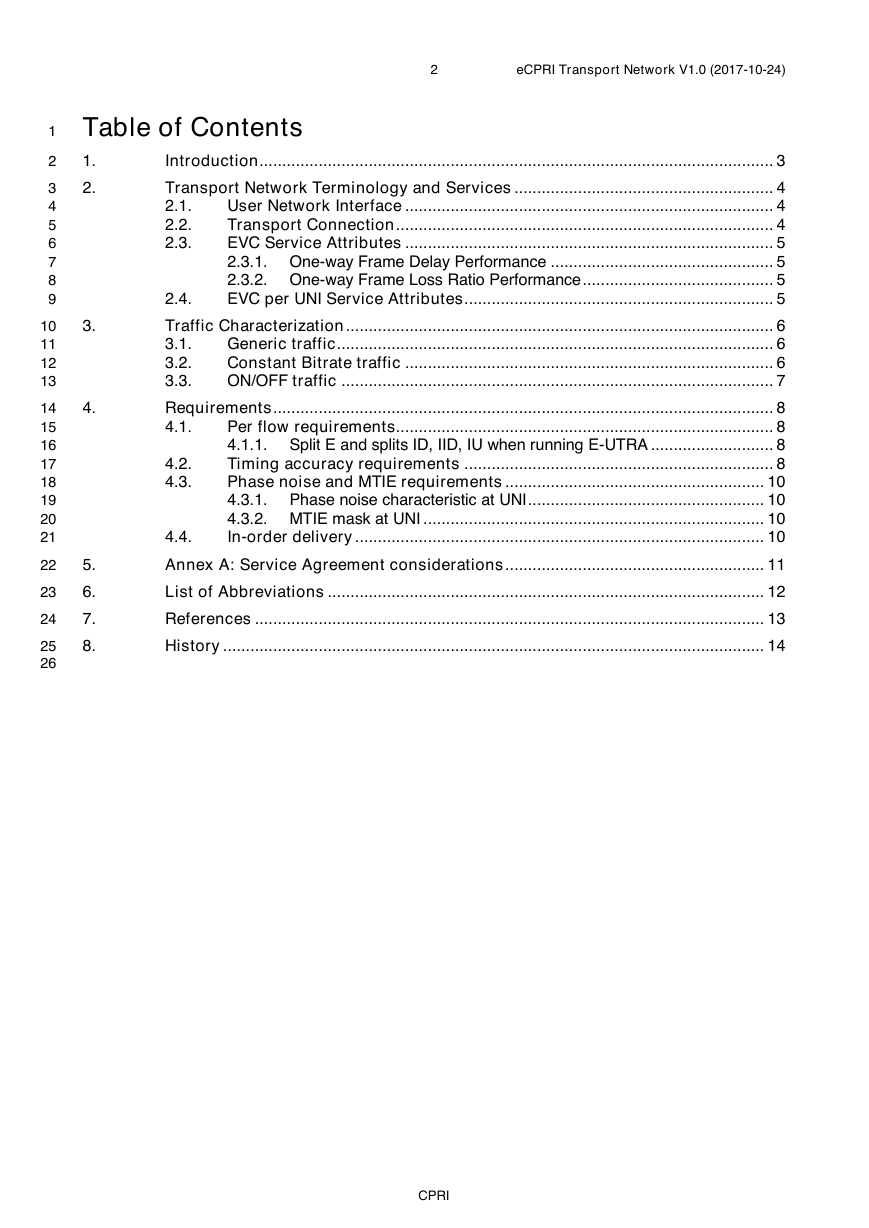
1.
Introduction ................................................................................................................. 3
2.
3.
4.
5.
6.
7.
8.
Transport Network Terminology and Services ......................................................... 4
User Network Interface ................................................................................. 4
2.1.
Transport Connection ................................................................................... 4
2.2.
EVC Service Attributes ................................................................................. 5
2.3.
2.3.1. One-way Frame Delay Performance ................................................. 5
2.3.2. One-way Frame Loss Ratio Performance .......................................... 5
EVC per UNI Service Attributes .................................................................... 5
2.4.
Traffic Characterization .............................................................................................. 6
Generic traffic ................................................................................................ 6
3.1.
Constant Bitrate traffic ................................................................................. 6
3.2.
3.3.
ON/OFF traffic ............................................................................................... 7
Requirements .............................................................................................................. 8
Per flow requirements................................................................................... 8
4.1.
4.1.1. Split E and splits ID, IID, IU when running E-UTRA ........................... 8
Timing accuracy requirements .................................................................... 8
Phase noise and MTIE requirements ......................................................... 10
4.3.1. Phase noise characteristic at UNI .................................................... 10
4.3.2. MTIE mask at UNI ........................................................................... 10
In-order delivery .......................................................................................... 10
4.2.
4.3.
4.4.
Annex A: Service Agreement considerations ......................................................... 11
List of Abbreviations ................................................................................................ 12
References ................................................................................................................ 13
History ....................................................................................................................... 14
CPRI
�
1
2
3
4
5
6
7
8
9
10
11
12
13
14
15
16
17
18
19
20
21
22
23
24
25
26
27
28
29
30
31
32
33
34
35
3
eCPRI Transport Network V1.0 (2017-10-24)
1. Introduction
The Common Public Radio Interface (CPRI) is an industry cooperation aimed at defining publicly available
specifications for the key internal interface of radio base stations, such as eCPRI connecting the eCPRI
Radio Equipment Control (eREC) and the eCPRI Radio Equipment (eRE) via a so-called fronthaul transport
network. The parties cooperating to define the specification are Ericsson AB, Huawei Technologies Co. Ltd,
NEC Corporation and Nokia.
The eCPRI Interface Specification [1] can be supported by Ethernet-switched or IP-routed fronthaul
networks, or similar types of transport networks. This specification describes the requirements that the
packet switched transport network must fulfill in order to support eCPRI services.
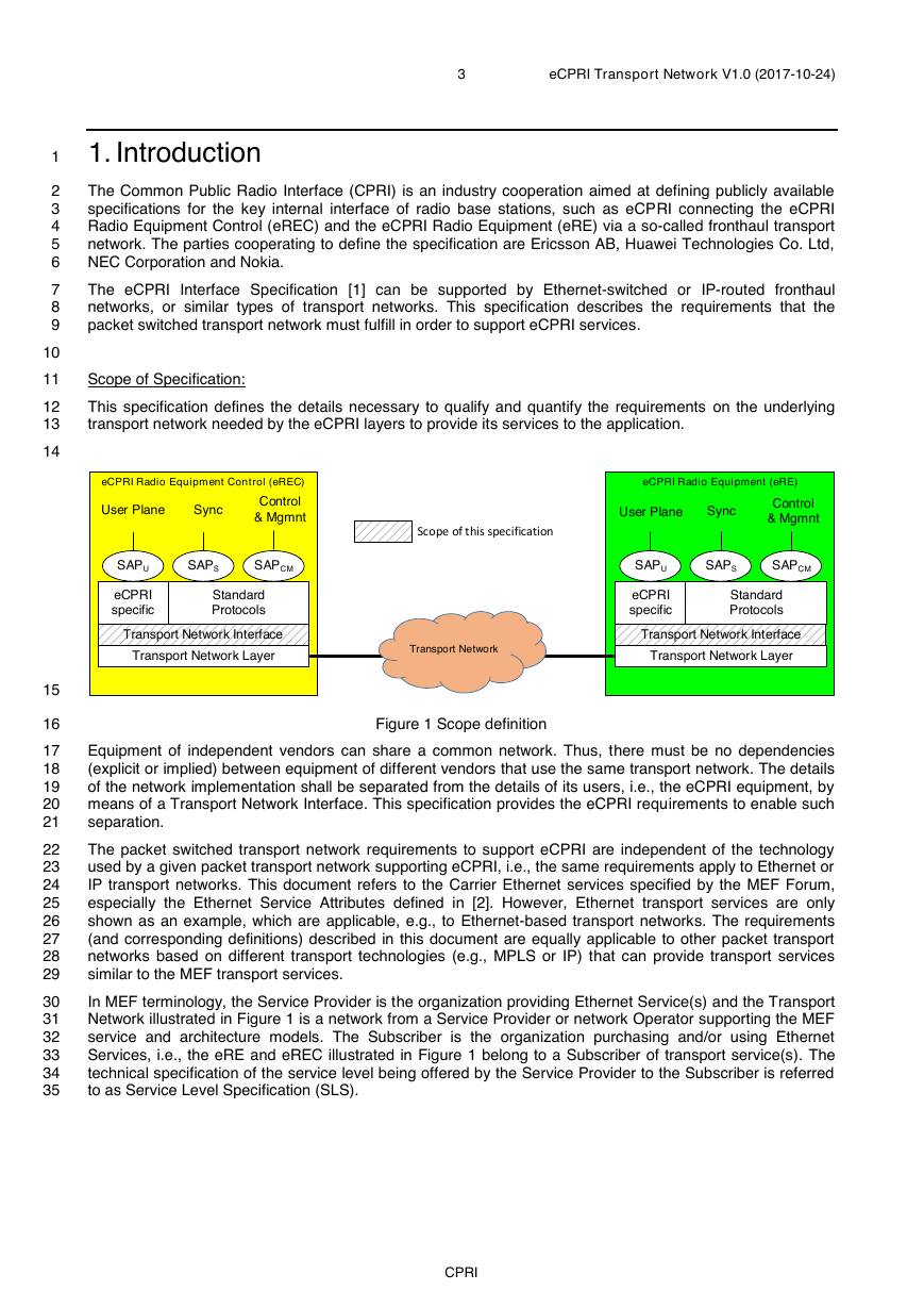
Scope of Specification:
This specification defines the details necessary to qualify and quantify the requirements on the underlying
transport network needed by the eCPRI layers to provide its services to the application.
Figure 1 Scope definition
Equipment of independent vendors can share a common network. Thus, there must be no dependencies
(explicit or implied) between equipment of different vendors that use the same transport network. The details
of the network implementation shall be separated from the details of its users, i.e., the eCPRI equipment, by
means of a Transport Network Interface. This specification provides the eCPRI requirements to enable such
separation.
The packet switched transport network requirements to support eCPRI are independent of the technology
used by a given packet transport network supporting eCPRI, i.e., the same requirements apply to Ethernet or
IP transport networks. This document refers to the Carrier Ethernet services specified by the MEF Forum,
especially the Ethernet Service Attributes defined in [2]. However, Ethernet transport services are only
shown as an example, which are applicable, e.g., to Ethernet-based transport networks. The requirements
(and corresponding definitions) described in this document are equally applicable to other packet transport
networks based on different transport technologies (e.g., MPLS or IP) that can provide transport services
similar to the MEF transport services.
In MEF terminology, the Service Provider is the organization providing Ethernet Service(s) and the Transport
Network illustrated in Figure 1 is a network from a Service Provider or network Operator supporting the MEF
service and architecture models. The Subscriber is the organization purchasing and/or using Ethernet
Services, i.e., the eRE and eREC illustrated in Figure 1 belong to a Subscriber of transport service(s). The
technical specification of the service level being offered by the Service Provider to the Subscriber is referred
to as Service Level Specification (SLS).
CPRI
eCPRI Radio Equipment Control (eREC)eCPRI specificUser PlaneSyncControl& MgmnteCPRI Radio Equipment (eRE)Transport Network Layer StandardProtocolsSAPUSAPSSAPCMeCPRI specificUser PlaneSyncControl& MgmntTransport Network Layer StandardProtocolsSAPUSAPSSAPCMTransport NetworkTransport Network Interface Transport Network Interface Scope of this specification�
1
2
3
4
5
6
7
8
9
10
11
12
13
14
15
16
17
18
19
20
21
22
4
eCPRI Transport Network V1.0 (2017-10-24)
2. Transport Network Terminology and Services
This section describes terminology, services, service attributes, etc. that are widely used for transport
networks. Although, this section largely refers to the terminology used by the MEF Forum, neither the
transport network nor the service provided is limited to Ethernet, other technologies and services, e.g., IP
can also be used.1
2.1. User Network Interface
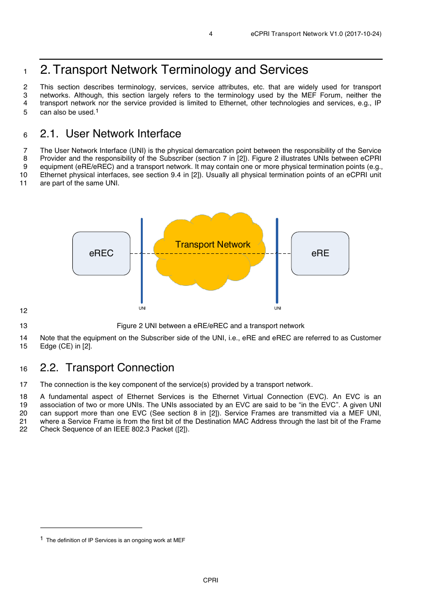
The User Network Interface (UNI) is the physical demarcation point between the responsibility of the Service
Provider and the responsibility of the Subscriber (section 7 in [2]). Figure 2 illustrates UNIs between eCPRI
equipment (eRE/eREC) and a transport network. It may contain one or more physical termination points (e.g.,
Ethernet physical interfaces, see section 9.4 in [2]). Usually all physical termination points of an eCPRI unit
are part of the same UNI.
Figure 2 UNI between a eRE/eREC and a transport network
Note that the equipment on the Subscriber side of the UNI, i.e., eRE and eREC are referred to as Customer
Edge (CE) in [2].
2.2. Transport Connection
The connection is the key component of the service(s) provided by a transport network.
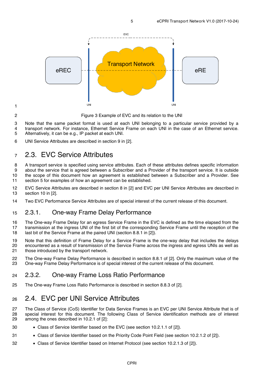
A fundamental aspect of Ethernet Services is the Ethernet Virtual Connection (EVC). An EVC is an
association of two or more UNIs. The UNIs associated by an EVC are said to be “in the EVC”. A given UNI
can support more than one EVC (See section 8 in [2]). Service Frames are transmitted via a MEF UNI,
where a Service Frame is from the first bit of the Destination MAC Address through the last bit of the Frame
Check Sequence of an IEEE 802.3 Packet ([2]).
1 The definition of IP Services is an ongoing work at MEF
CPRI
eRECeRETransport NetworkUNIUNI�
5
eCPRI Transport Network V1.0 (2017-10-24)
1
2
3
4
5
6
7
8
9
10
11
12
13
14
15
16
17
18
19
20
21
22
23
24
Figure 3 Example of EVC and its relation to the UNI
Note that the same packet format is used at each UNI belonging to a particular service provided by a
transport network. For instance, Ethernet Service Frame on each UNI in the case of an Ethernet service.
Alternatively, it can be e.g., IP packet at each UNI.
UNI Service Attributes are described in section 9 in [2].
2.3. EVC Service Attributes
A transport service is specified using service attributes. Each of these attributes defines specific information
about the service that is agreed between a Subscriber and a Provider of the transport service. It is outside
the scope of this document how an agreement is established between a Subscriber and a Provider. See
section 5 for examples of how an agreement can be established.
EVC Service Attributes are described in section 8 in [2] and EVC per UNI Service Attributes are described in
section 10 in [2].
Two EVC Performance Service Attributes are of special interest of the current release of this document.
2.3.1.
One-way Frame Delay Performance
The One-way Frame Delay for an egress Service Frame in the EVC is defined as the time elapsed from the
transmission at the ingress UNI of the first bit of the corresponding Service Frame until the reception of the
last bit of the Service Frame at the paired UNI (section 8.8.1 in [2]).
Note that this definition of Frame Delay for a Service Frame is the one-way delay that includes the delays
encountered as a result of transmission of the Service Frame across the ingress and egress UNIs as well as
those introduced by the transport network.
The One-way Frame Delay Performance is described in section 8.8.1 of [2]. Only the maximum value of the
One-way Frame Delay Performance is of special interest of the current release of this document.
2.3.2.
One-way Frame Loss Ratio Performance
25
The One-way Frame Loss Ratio Performance is described in section 8.8.3 of [2].
26
27
28
29
30
31
32
2.4. EVC per UNI Service Attributes
The Class of Service (CoS) Identifier for Data Service Frames is an EVC per UNI Service Attribute that is of
special interest for this document. The following Class of Service identification methods are of interest
among the ones described in 10.2.1 of [2]:
• Class of Service Identifier based on the EVC (see section 10.2.1.1 of [2]).
• Class of Service Identifier based on the Priority Code Point Field (see section 10.2.1.2 of [2]).
• Class of Service Identifier based on Internet Protocol (see section 10.2.1.3 of [2]).
CPRI
eRECeRETransport NetworkUNIUNIEVC�
1
2
3
4
5
6
7
8
9
10
11
12
13
14
15
16
17
18
19
20
21
22
23
24
25
26
6
eCPRI Transport Network V1.0 (2017-10-24)
3. Traffic Characterization
This section provides a general model based on MEF’s Generic Token Bucket Algorithm (GTBA) and some
examples of simple traffic models. A list of performance service attributes is provided for each model as a
blueprint for service agreement terms between a Subscriber and a Provider. Neither the set of models
included nor each model individually is exhaustive or a perfect characterization of the real-life traffic covering
all cases.
In the following sub-sections, physical bit rate refers to the physical line bit rate of the transmitting UNI.
3.1. Generic traffic
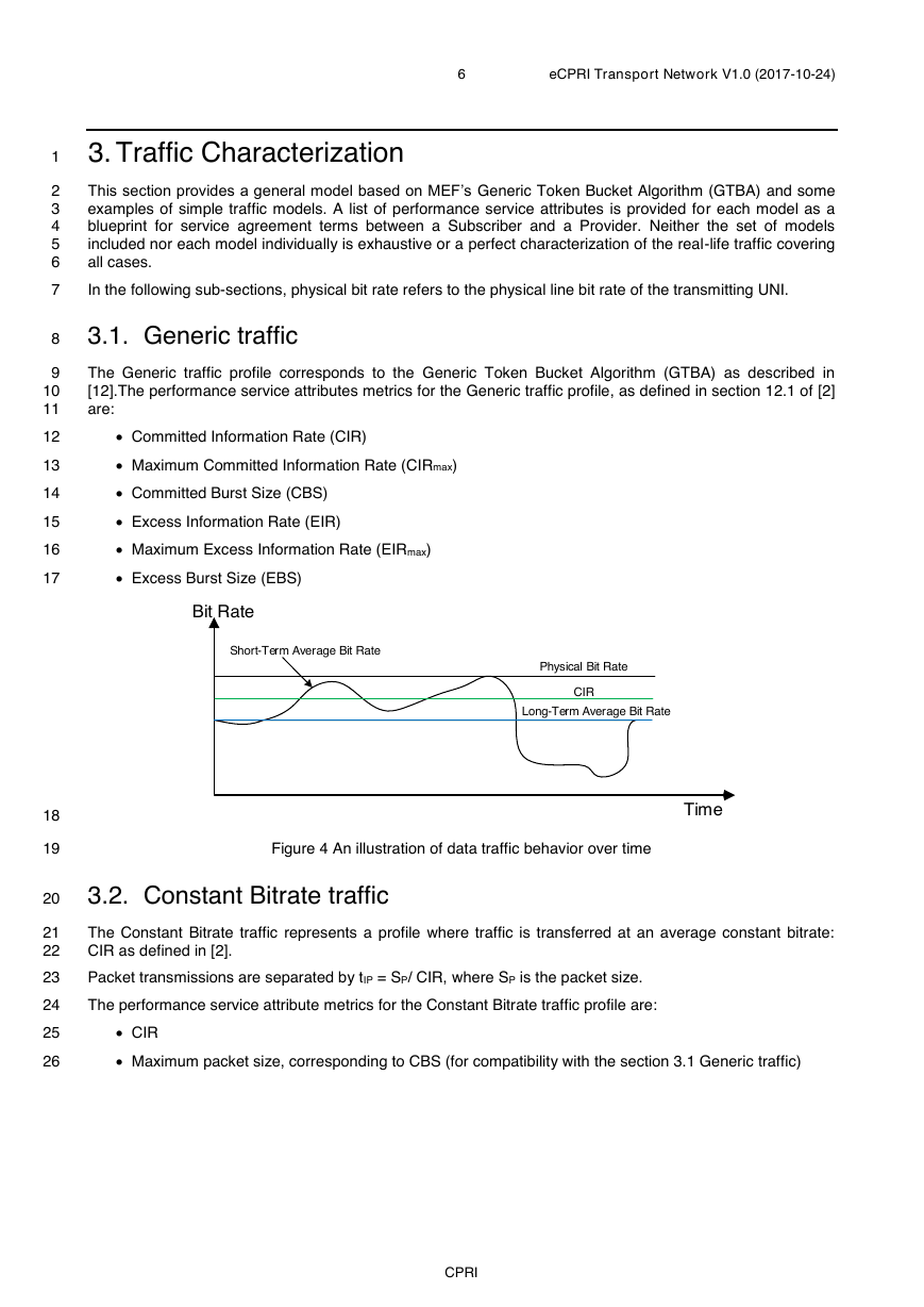
The Generic traffic profile corresponds to the Generic Token Bucket Algorithm (GTBA) as described in
[12].The performance service attributes metrics for the Generic traffic profile, as defined in section 12.1 of [2]
are:
• Committed Information Rate (CIR)
• Maximum Committed Information Rate (CIRmax)
• Committed Burst Size (CBS)
• Excess Information Rate (EIR)
• Maximum Excess Information Rate (EIRmax)
• Excess Burst Size (EBS)
Figure 4 An illustration of data traffic behavior over time
3.2. Constant Bitrate traffic
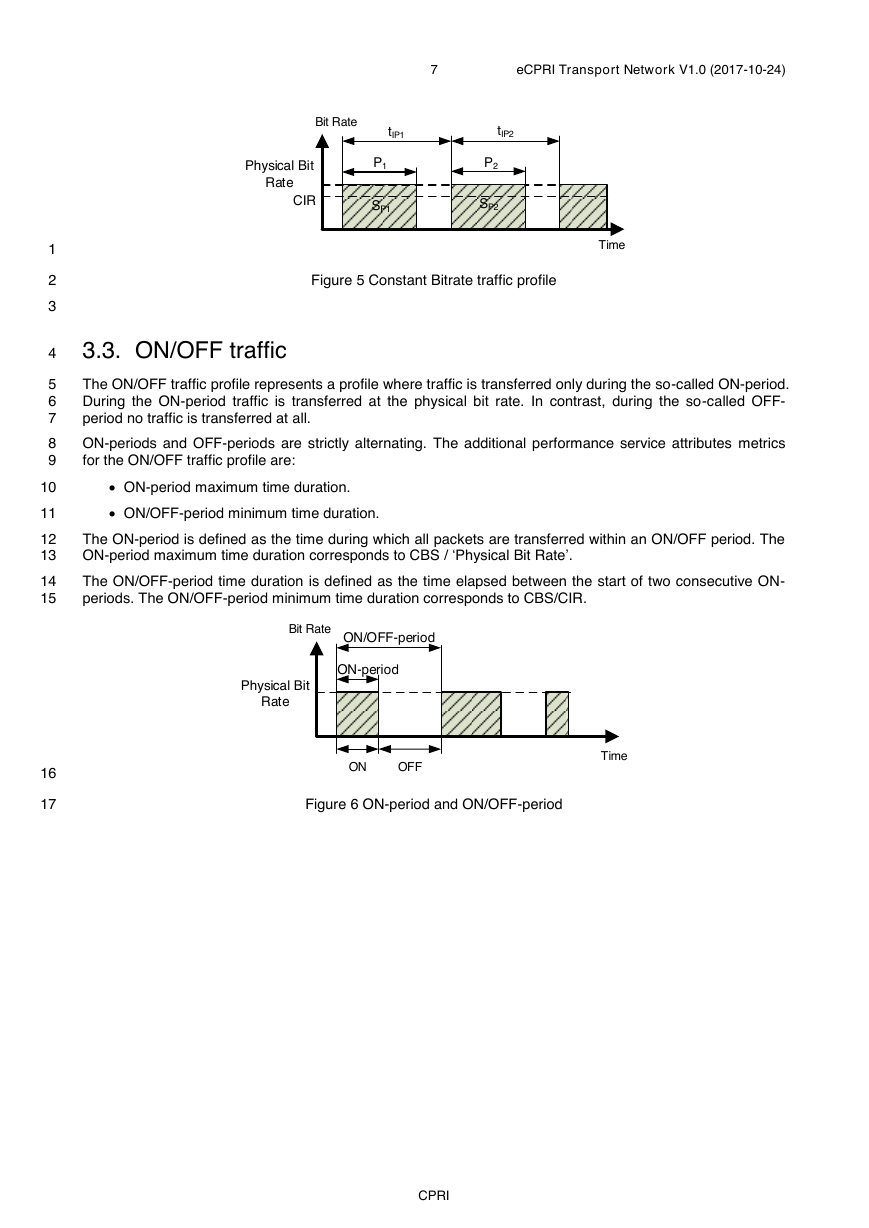
The Constant Bitrate traffic represents a profile where traffic is transferred at an average constant bitrate:
CIR as defined in [2].
Packet transmissions are separated by tIP = SP/ CIR, where SP is the packet size.
The performance service attribute metrics for the Constant Bitrate traffic profile are:
• CIR
• Maximum packet size, corresponding to CBS (for compatibility with the section 3.1 Generic traffic)
CPRI
Bit RateTimeLong-Term Average Bit Rate Short-Term Average Bit RatePhysical Bit RateCIR�
1
2
3
4
5
6
7
8
9
10
11
12
13
14
15
16
17
7
eCPRI Transport Network V1.0 (2017-10-24)
Figure 5 Constant Bitrate traffic profile
3.3. ON/OFF traffic
The ON/OFF traffic profile represents a profile where traffic is transferred only during the so-called ON-period.
During the ON-period traffic is transferred at the physical bit rate. In contrast, during the so-called OFF-
period no traffic is transferred at all.
ON-periods and OFF-periods are strictly alternating. The additional performance service attributes metrics
for the ON/OFF traffic profile are:
• ON-period maximum time duration.
• ON/OFF-period minimum time duration.
The ON-period is defined as the time during which all packets are transferred within an ON/OFF period. The
ON-period maximum time duration corresponds to CBS / ‘Physical Bit Rate’.
The ON/OFF-period time duration is defined as the time elapsed between the start of two consecutive ON-
periods. The ON/OFF-period minimum time duration corresponds to CBS/CIR.
Figure 6 ON-period and ON/OFF-period
CPRI
Bit RateTimeP1tIP1Physical Bit RateCIRtIP2P2SP1SP2Bit RateONOFFTimeON-periodON/OFF-periodPhysical Bit Rate�
8
eCPRI Transport Network V1.0 (2017-10-24)
1
2
3
4
5
4. Requirements
4.1. Per flow requirements
4.1.1.
Split E and splits ID, IID, IU when running E-UTRA
Table 1 is applicable for the functional decompositions splits E and ID, IID, IU as defined in [1].
Table 1 Split E and splits ID, IID, IU requirements
CoS Name Example use
One-way maximum
packet delay
One-way Packet
Loss Ratio
High
User Plane
100 µs
Medium
User Plane
(slow),
1 ms
C&M Plane (fast)
Low
C&M Plane
100 ms
10-7
10-7
10-6
6
7
8
9
10
11
12
13
14
15
16
4.2. Timing accuracy requirements
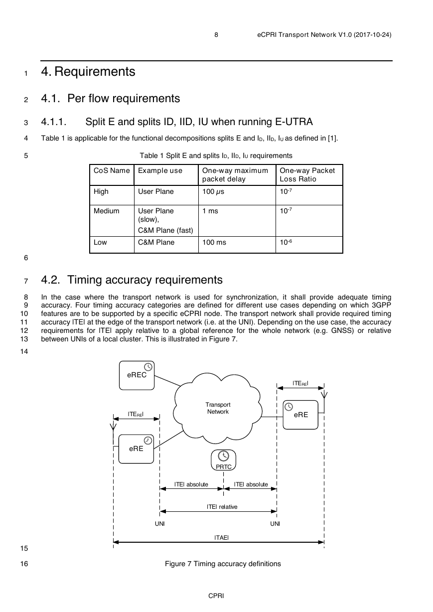
In the case where the transport network is used for synchronization, it shall provide adequate timing
accuracy. Four timing accuracy categories are defined for different use cases depending on which 3GPP
features are to be supported by a specific eCPRI node. The transport network shall provide required timing
accuracy |TE| at the edge of the transport network (i.e. at the UNI). Depending on the use case, the accuracy
requirements for |TE| apply relative to a global reference for the whole network (e.g. GNSS) or relative
between UNIs of a local cluster. This is illustrated in Figure 7.
Figure 7 Timing accuracy definitions
CPRI
TransportNetworkeREeRECeRE|TERE||TE| relative|TERE|UNI|TAE|UNIPRTC|TE| absolute|TE| absolute�


 2023年江西萍乡中考道德与法治真题及答案.doc
 2012年重庆南川中考生物真题及答案.doc
 2013年江西师范大学地理学综合及文艺理论基础考研真题.doc
 2020年四川甘孜小升初语文真题及答案I卷.doc
 2020年注册岩土工程师专业基础考试真题及答案.doc
 2023-2024学年福建省厦门市九年级上学期数学月考试题及答案.doc
 2021-2022学年辽宁省沈阳市大东区九年级上学期语文期末试题及答案.doc
 2022-2023学年北京东城区初三第一学期物理期末试卷及答案.doc
 2018上半年江西教师资格初中地理学科知识与教学能力真题及答案.doc
 2012年河北国家公务员申论考试真题及答案-省级.doc
 2020-2021学年江苏省扬州市江都区邵樊片九年级上学期数学第一次质量检测试题及答案.doc
 2022下半年黑龙江教师资格证中学综合素质真题及答案.doc