GDS-806/810/820/840 Programming Manual
Table of Contents Pages
1. INTRODUCTION................................................................................................................... 2
2. COMPUTER’S CONNECTION............................................................................................. 6
3. REMOTE CONTROL'S COMMANDS ................................................................................ 12
4. DETAILS OF COMMAND REFERENCE ........................................................................... 19
5. STATUS REPORTS............................................................................................................ 73
6. PROGRAM TEMPLATE FOR GPIB................................................................................... 81
7. APPENDIX A: HOW CAN WE CONVERT THE HEXADECIMAL FORMAT TO A
FLOATING POINT FORMAT. ................................................................................................ 89
Due to continuous improvements in the GDS-806/810/820/840 Digital Storage
Oscilloscope, information contained in this manual is subject to change
without notice. Contact GOOD WILL, for revisions and corrections.
GOOD WILL Instrument Co., LTD.
No.7-1, Jhongsing Rd., Tucheng City,
Taipei County 236, Taiwan
Telephone – 886-2-22680389 Fax – 886-2-22680639
E-mail - marketing@goodwill.com.tw
http://www.goodwill.com.tw
0
�
GDS-806/810/820/840 Programming Manual
1. Introduction
Users can drive this digital storage oscilloscope by using the GPIB (General
Purpose Interface Bus) system with a computer, or from a computer across the
RS-232 serial connection. Commands sent over either interface can read or set any
oscilloscope’s instructions. This chapter explains how to carry out the following
tasks.
Notes for GPIB installation
If you are setting up the oscilloscope with a GPIB system, please check the
following regulations:
Only a maximum of 15 devices can be connected to a single GPIB bus.
Do not use more than 20 m of cable to connect devices to a bus.
Connect one device for every 2 m of cable used.
Each device on the bus needs a unique device address. No two devices can
share the same device address.
Turn on at least two-thirds of the devices on the GPIB system while you use the
system.
Do not use loop or parallel structure for the topology of GPIB system.
1
�
GDS-806/810/820/840 Programming Manual
Notes for RS-232 Configuration
This oscilloscope contains a DB 9-pin, male RS-232 connector for serial
communication with a computer or terminal. The RS-232 interface of this
oscilloscope is configured as an RS-232 “Data Terminal Equipment”, so that data
is sent from pin 3 and received on pin 2. For remote controls, the RS-232 interface
has to be connected with a computer or terminal.
Pin Assignments
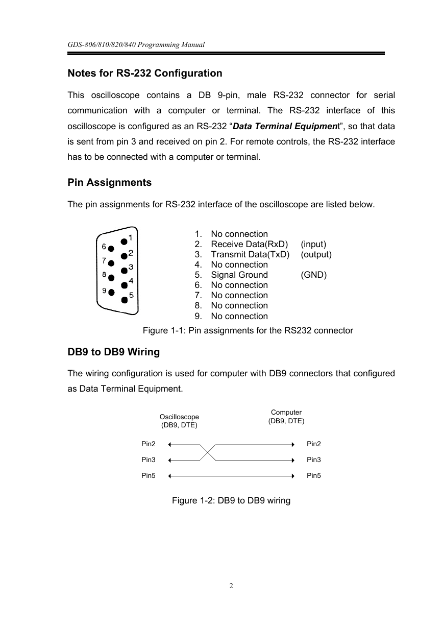
The pin assignments for RS-232 interface of the oscilloscope are listed below.
1. No connection
2. Receive Data(RxD)
3. Transmit Data(TxD)
4. No connection
5. Signal Ground
6. No connection
7. No connection
8. No connection
9. No connection
(input)
(output)
(GND)
Figure 1-1: Pin assignments for the RS232 connector
DB9 to DB9 Wiring
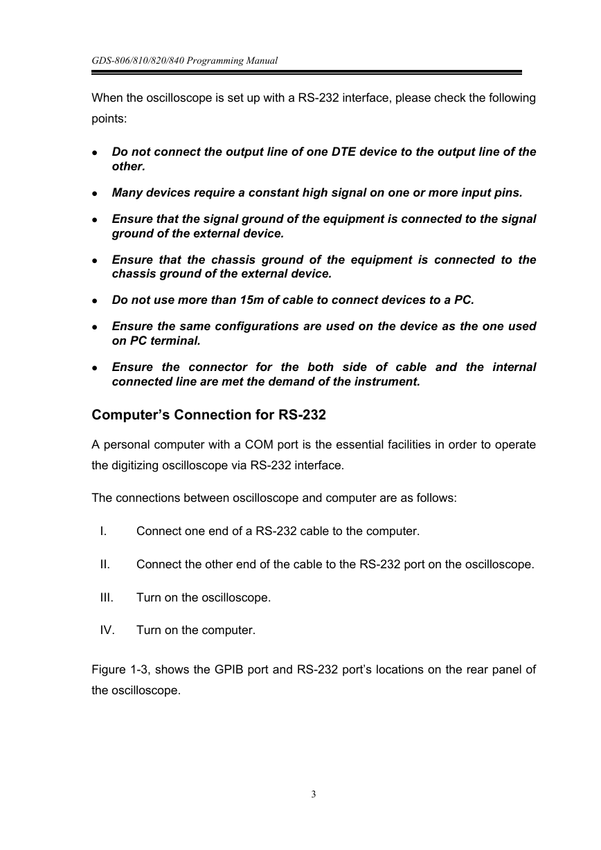
The wiring configuration is used for computer with DB9 connectors that configured
as Data Terminal Equipment.
Oscilloscope
(DB9, DTE)
Computer
(DB9, DTE)
Pin2
Pin3
Pin5
Pin2
Pin3
Pin5
Figure 1-2: DB9 to DB9 wiring
2
�
GDS-806/810/820/840 Programming Manual
When the oscilloscope is set up with a RS-232 interface, please check the following
points:
Do not connect the output line of one DTE device to the output line of the
other.
Many devices require a constant high signal on one or more input pins.
Ensure that the signal ground of the equipment is connected to the signal
ground of the external device.
Ensure that the chassis ground of the equipment is connected to the
chassis ground of the external device.
Do not use more than 15m of cable to connect devices to a PC.
Ensure the same configurations are used on the device as the one used
on PC terminal.
Ensure the connector for the both side of cable and the internal
connected line are met the demand of the instrument.
Computer’s Connection for RS-232
A personal computer with a COM port is the essential facilities in order to operate
the digitizing oscilloscope via RS-232 interface.
The connections between oscilloscope and computer are as follows:
I.
II.
Connect one end of a RS-232 cable to the computer.
Connect the other end of the cable to the RS-232 port on the oscilloscope.
III.
Turn on the oscilloscope.
IV.
Turn on the computer.
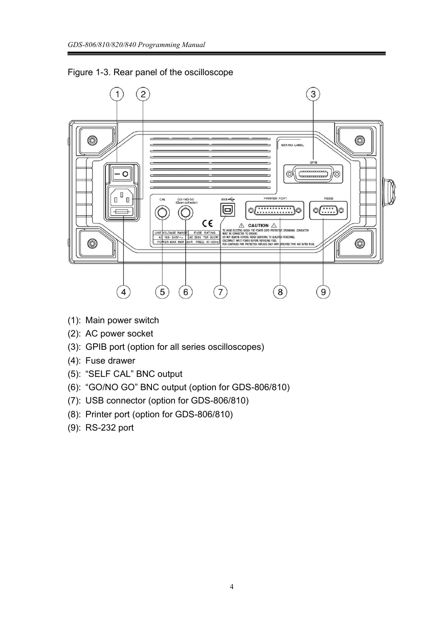
Figure 1-3, shows the GPIB port and RS-232 port’s locations on the rear panel of
the oscilloscope.
3
�
GDS-806/810/820/840 Programming Manual
Figure 1-3. Rear panel of the oscilloscope
(1): Main power switch
(2): AC power socket
(3): GPIB port (option for all series oscilloscopes)
(4): Fuse drawer
(5): “SELF CAL” BNC output
(6): “GO/NO GO” BNC output (option for GDS-806/810)
(7): USB connector (option for GDS-806/810)
(8): Printer port (option for GDS-806/810)
(9): RS-232 port
4
�
GDS-806/810/820/840 Programming Manual
2. Computer’s Connection
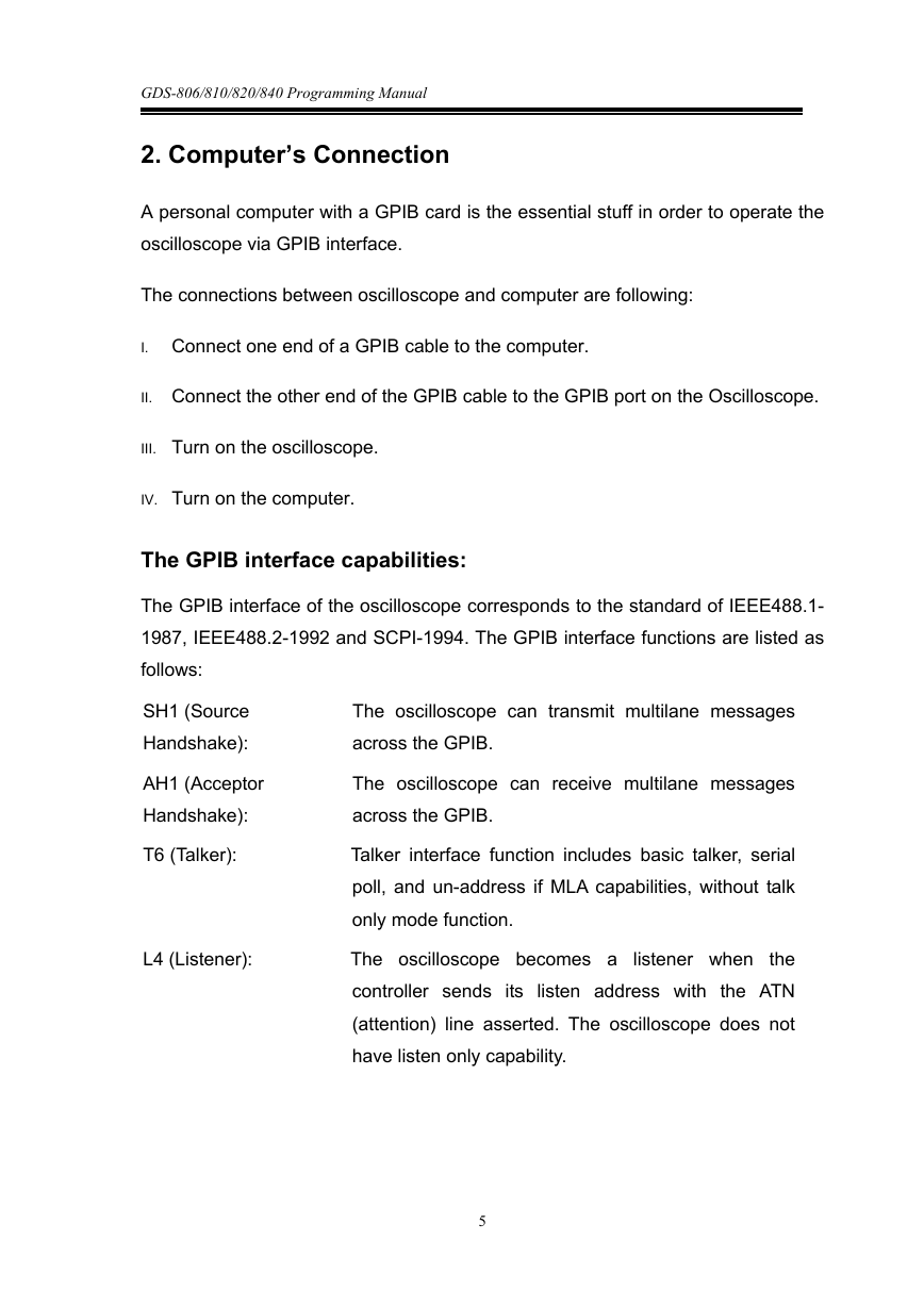
A personal computer with a GPIB card is the essential stuff in order to operate the
oscilloscope via GPIB interface.
The connections between oscilloscope and computer are following:
I. Connect one end of a GPIB cable to the computer.
II. Connect the other end of the GPIB cable to the GPIB port on the Oscilloscope.
III. Turn on the oscilloscope.
IV. Turn on the computer.
The GPIB interface capabilities:
The GPIB interface of the oscilloscope corresponds to the standard of IEEE488.1-
1987, IEEE488.2-1992 and SCPI-1994. The GPIB interface functions are listed as
follows:
SH1 (Source
Handshake):
AH1 (Acceptor
Handshake):
T6 (Talker):
L4 (Listener):
The oscilloscope can transmit multilane messages
across the GPIB.
The oscilloscope can receive multilane messages
across the GPIB.
Talker interface function includes basic talker, serial
poll, and un-address if MLA capabilities, without talk
only mode function.
listener when
the
The oscilloscope becomes a
controller sends its listen address with the ATN
(attention) line asserted. The oscilloscope does not
have listen only capability.
5
�
GDS-806/810/820/840 Programming Manual
SR0 (Service Request): The oscilloscope has no SRQ (Service request)
function.
RL2 (Remote/Local):
PP0 (Parallel Poll):
DC1 (Device Clear):
DT0 (Device Trigger):
The oscilloscope will ignore the LLO (local lockout)
command.
The oscilloscope has no Parallel Poll
function.
interface
The oscilloscope has Device clear capability to return
the device to power on status.
The oscilloscope has no Device Trigger interface
function.
C0 (Controller) : This oscilloscope can not control other devices.
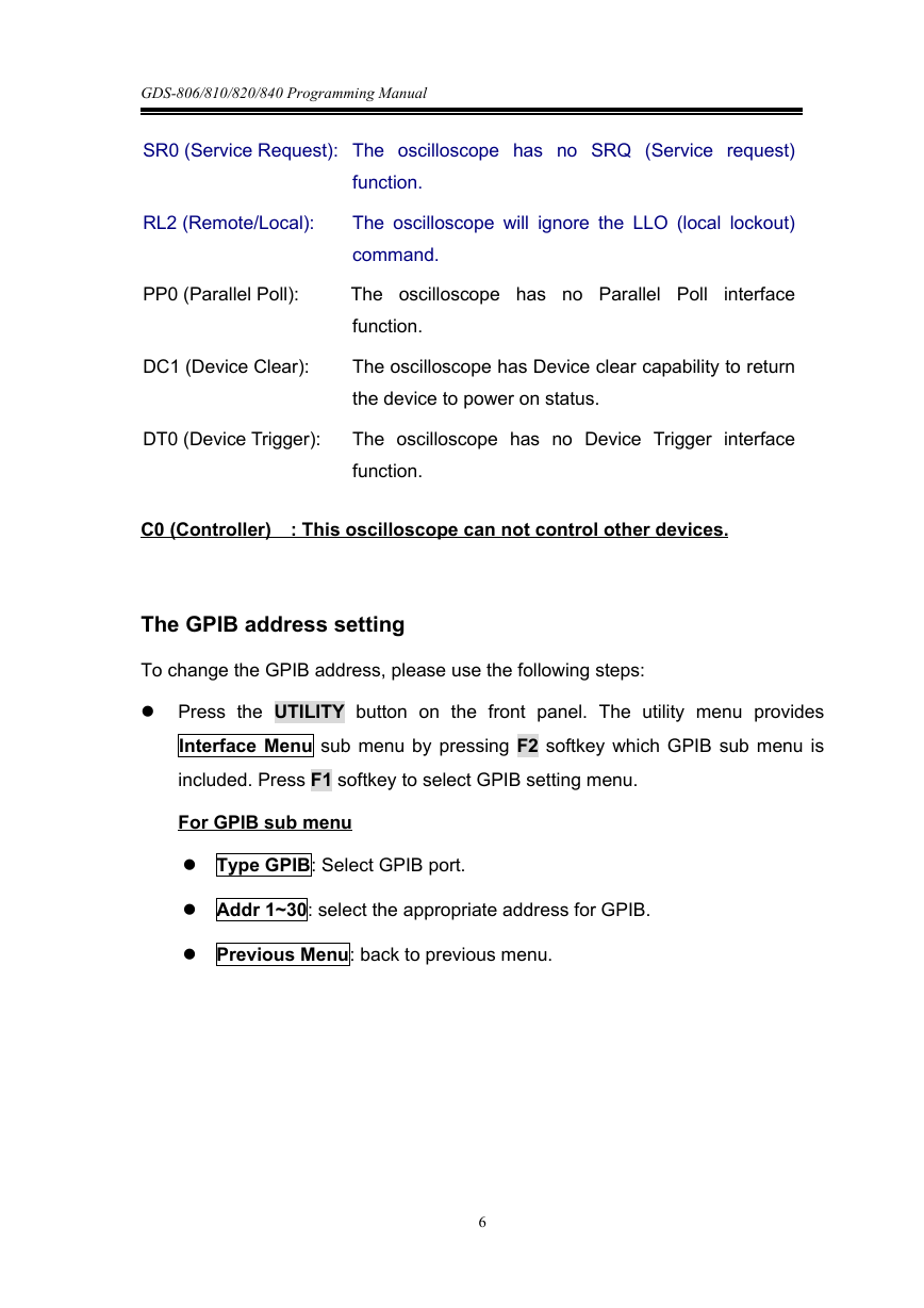
The GPIB address setting
To change the GPIB address, please use the following steps:
Press the UTILITY button on the front panel. The utility menu provides
Interface Menu sub menu by pressing F2 softkey which GPIB sub menu is
included. Press F1 softkey to select GPIB setting menu.
For GPIB sub menu
Type GPIB: Select GPIB port.
Addr 1~30: select the appropriate address for GPIB.
Previous Menu: back to previous menu.
6
�
GDS-806/810/820/840 Programming Manual
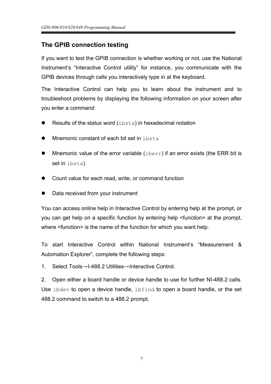
The GPIB connection testing
If you want to test the GPIB connection is whether working or not, use the National
Instrument’s “Interactive Control utility” for instance, you communicate with the
GPIB devices through calls you interactively type in at the keyboard.
The Interactive Control can help you to learn about the instrument and to
troubleshoot problems by displaying the following information on your screen after
you enter a command:
Results of the status word (ibsta) in hexadecimal notation
Mnemonic constant of each bit set in ibsta
Mnemonic value of the error variable (iberr) if an error exists (the ERR bit is
set in ibsta)
Count value for each read, write, or command function
Data received from your instrument
You can access online help in Interactive Control by entering help at the prompt, or
you can get help on a specific function by entering help at the prompt,
where is the name of the function for which you want help.
Interactive Control within National
To start
Automation Explorer”, complete the following steps:
Instrument’s “Measurement &
1. Select Tools→I-488.2 Utilities→Interactive Control.
2. Open either a board handle or device handle to use for further NI-488.2 calls.
Use ibdev to open a device handle, ibfind to open a board handle, or the set
488.2 command to switch to a 488.2 prompt.
7
�



 2023年江西萍乡中考道德与法治真题及答案.doc
 2012年重庆南川中考生物真题及答案.doc
 2013年江西师范大学地理学综合及文艺理论基础考研真题.doc
 2020年四川甘孜小升初语文真题及答案I卷.doc
 2020年注册岩土工程师专业基础考试真题及答案.doc
 2023-2024学年福建省厦门市九年级上学期数学月考试题及答案.doc
 2021-2022学年辽宁省沈阳市大东区九年级上学期语文期末试题及答案.doc
 2022-2023学年北京东城区初三第一学期物理期末试卷及答案.doc
 2018上半年江西教师资格初中地理学科知识与教学能力真题及答案.doc
 2012年河北国家公务员申论考试真题及答案-省级.doc
 2020-2021学年江苏省扬州市江都区邵樊片九年级上学期数学第一次质量检测试题及答案.doc
 2022下半年黑龙江教师资格证中学综合素质真题及答案.doc