S-91 Manual V1.0
GPS Engine Board Manual
S-91
SiRF StarⅢ
V 1.0
Made in Taiwan
www.dagamagps.com
2008/08/08
E-mail:service@dagamagps.com
Free service hot-line(for mainland):400-820-1322
The Specifications are subject to be changed without notice. Copyright @ 2008, Dagama Navigation. 1 of 25
Confidential 2008/08/08 Version:1.0
�
Contents
S-91 Manual V1.0
1 INTRODUCTION ------------------------------------------------------------------------------------- 3
1.1 OVERVIEW ------------------------------------------------------------------------------------ 3
1.2 MAIN FEATURES ---------------------------------------------------------------------------- 3
1.3 SPECIFICATIONS ---------------------------------------------------------------------------- 4
1.4 PROTOCOLS ---------------------------------------------------------------------------------- 5
1.5 PROGRAMMING RESOURCES --------------------------------------------------------- 5
1.6 ANTENNA -------------------------------------------------------------------------------------- 5
2 HARDWARE INTERFACE -------------------------------------------------------------------------- 6
2.1 PCB DIMENSION ---------------------------------------------------------------------------- 6
2.2 PIN ASSIGNMENT --------------------------------------------------------------------------- 7
2.3 LAYOUT SUGGESTION -------------------------------------------------------------------- 10
2.4 POWER SAVING ----------------------------------------------------------------------------- 10
2.5 ANTENNA APPLICATION ----------------------------------------------------------------- 11
2.6 RF_IN IMPEDANCE MATCHING -------------------------------------------------------- 15
2.7 1PPS OUTPUT -------------------------------------------------------------------------------- 17
3 SOFTWARE INTERFACE --------------------------------------------------------------------------- 17
3.1 NMEA OUTPUT MESSAGES--------------------------------------------------------------- 17
3.2 GPGGA - GLOBAL POSITIONING SYSTEM FIX DATA ----------------------------- 18
3.3 GPGLL - GEOGRAPHIC POSITION - LATITUDE / LONGITUDE ------------------ 29
3.4 GPGSA - GNSS DOP AND ACTIVE SATELLITES -------------------------------------- 20
3.5 GPGSV - GNSS SATELLITES IN VIEW --------------------------------------------------- 20
3.6 GPRMC - RECOMMENDED MINIMUM SPECIFIC GNSS DATA ------------------- 21
3.7 GPVTG - COURSE OVER GROUND AND GROUND SPEED ------------------------ 22
3.8 GPZDA - SIRF TIMING MESSAGE -------------------------------------------------------- 23
3.9 GPADT – PROGIN ANTENNA DETECTION MESSAGE ------------------------------ 23
The Specifications are subject to be changed without notice. Copyright @ 2008, Dagama Navigation. 2 of 25
Confidential 2008/08/08 Version:1.0
�
S-91 Manual V1.0
1. Introduction
1.1 Overview
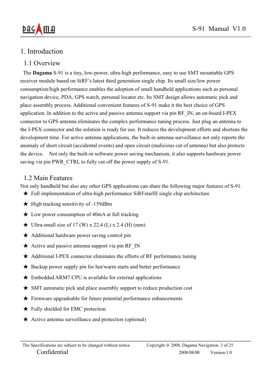
The Dagama S-91 is a tiny, low-power, ultra-high performance, easy to use SMT mountable GPS
receiver module based on SiRF’s latest third generation single chip. Its small size/low power
consumption/high performance enables the adoption of small handheld applications such as personal
navigation device, PDA, GPS watch, personal locator etc. Its SMT design allows automatic pick and
place assembly process. Additional convenient features of S-91 make it the best choice of GPS
application. In addition to the active and passive antenna support via pin RF_IN, an on-board I-PEX
connector to GPS antenna eliminates the complex performance tuning process. Just plug an antenna to
the I-PEX connector and the solution is ready for use. It reduces the development efforts and shortens the
development time. For active antenna applications, the built-in antenna surveillance not only reports the
anomaly of short circuit (accidental events) and open circuit (malicious cut of antenna) but also protects
the device. Not only the built-in software power saving mechanism, it also supports hardware power
saving via pin PWR_CTRL to fully cut off the power supply of S-91.
1.2 Main Features
Not only handheld but also any other GPS applications can share the following major features of S-91.
★ Full implementation of ultra-high performance SiRFstarIII single chip architecture
★ High tracking sensitivity of -159dBm
★ Low power consumption of 40mA at full tracking
★ Ultra-small size of 17 (W) x 22.4 (L) x 2.4 (H) (mm)
★ Additional hardware power saving control pin
★ Active and passive antenna support via pin RF_IN
★ Additional I-PEX connector eliminates the efforts of RF performance tuning
★ Backup power supply pin for hot/warm starts and better performance
★ Embedded ARM7 CPU is available for external applications
★ SMT automatic pick and place assembly support to reduce production cost
★ Firmware upgradeable for future potential performance enhancements
★ Fully shielded for EMC protection
★ Active antenna surveillance and protection (optional)
The Specifications are subject to be changed without notice. Copyright @ 2008, Dagama Navigation. 3 of 25
Confidential 2008/08/08 Version:1.0
�
1.3. Technical Specifications
1.3.1. Electrical Characteristics
◆ GPS receiver type
S-91 Manual V1.0
20 channels, L1 frequency, C/A code
◆ Horizontal Position Accuracy < 2.5m (Autonomous)
< 2.0m (WAAS)
(50% 24hr static, -130dBm)
◆ Velocity Accuracy
<0.01 m/s (speed)
<0.01° (heading)
(50%@30m/s)
◆ Time accuracy
1μs or less
◆ TTFF (Time to First Fix)
Hot Start: 1s
(50%, -130dBm, autonomous) Warm Start: 35s
Cold Start: 42s
◆ Sensitivity
(Autonomous)
Tracking: –159dBm
Acquisition: -142dBm
(-142dBm 28dB-Hz with 4dB noise figure)
◆ Measurement data output
Update time: 1 second
NMEA output protocol: V.3.00
Baud rate: 4800 (default), 9600, 19200, 38400,
57600 bps (8-N-1)
Datum: WGS-84
Default: GGA, GSA, RMC, VTG at 1Hz and
GSV at 1/5Hz
Other options: GLL, ZDA, or SiRF binary
◆ Max. Altitude
◆ Max. Velocity
◆ SBAS Support
<18,000 m
<1,852 km/hr
WAAS, EGNOS
The Specifications are subject to be changed without notice. Copyright @ 2008, Dagama Navigation. 4 of 25
Confidential 2008/08/08 Version:1.0
�
S-91 Manual V1.0
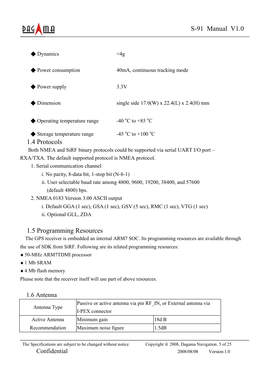
◆ Dynamics
<4g
◆ Power consumption
◆ Power supply
◆ Dimension
40mA, continuous tracking mode
3.3V
single side 17.0(W) x 22.4(L) x 2.4(H) mm
◆ Operating temperature range
◆ Storage temperature range
1.4 Protocols
Both NMEA and SiRF binary protocols could be supported via serial UART I/O port –
-45 oC to +100 oC
-40 oC to +85 oC
RXA/TXA. The default supported protocol is NMEA protocol.
1. Serial communication channel
i. No parity, 8-data bit, 1-stop bit (N-8-1)
ii. User selectable baud rate among 4800, 9600, 19200, 38400, and 57600
(default 4800) bps.
2. NMEA 0183 Version 3.00 ASCII output
i. Default GGA (1 sec), GSA (1 sec), GSV (5 sec), RMC (1 sec), VTG (1 sec)
ii. Optional GLL, ZDA
1.5 Programming Resources
The GPS receiver is embedded an internal ARM7 SOC. Its programming resources are available through
the use of SDK from SiRF. Following are its related programming resources:
◆ 50-MHz ARM7TDMI processor
◆ 1 Mb SRAM
◆ 4 Mb flash memory
Please note that the receiver itself will use part of above resources.
1.6 Antenna
Antenna Type
Active Antenna
Recommendation
Passive or active antenna via pin RF_IN, or External antenna via
I-PEX connector
Minimum gain
Maximum noise figure
18d B
1.5dB
The Specifications are subject to be changed without notice. Copyright @ 2008, Dagama Navigation. 5 of 25
Confidential 2008/08/08 Version:1.0
�
S-91 Manual V1.0
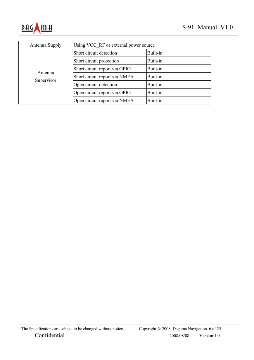
Antenna Supply
Antenna
Supervisor
Using VCC_RF or external power source
Short circuit detection
Short circuit protection
Short circuit report via GPIO
Short circuit report via NMEA
Open circuit detection
Open circuit report via GPIO
Open circuit report via NMEA
Built-in
Built-in
Built-in
Built-in
Built-in
Built-in
Built-in
The Specifications are subject to be changed without notice. Copyright @ 2008, Dagama Navigation. 6 of 25
Confidential 2008/08/08 Version:1.0
�
2 Hardware Interface
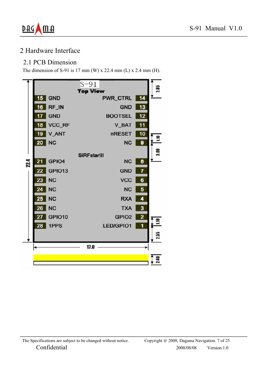
2.1 PCB Dimension
The dimension of S-91 is 17 mm (W) x 22.4 mm (L) x 2.4 mm (H).
S-91 Manual V1.0
The Specifications are subject to be changed without notice. Copyright @ 2008, Dagama Navigation. 7 of 25
Confidential 2008/08/08 Version:1.0
�
2.2 Pin Assignment
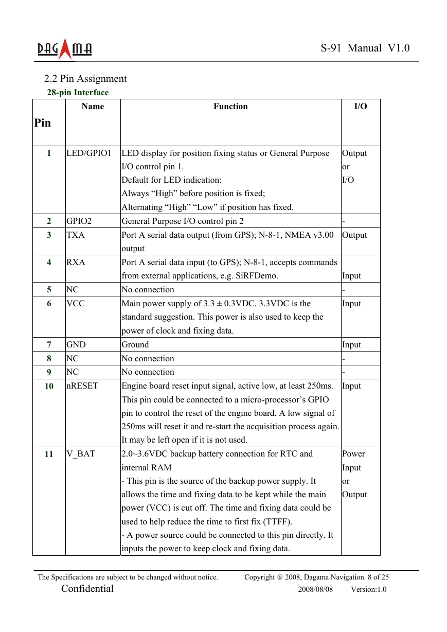
28-pin Interface
Name
Function
S-91 Manual V1.0
Pin
1
LED/GPIO1 LED display for position fixing status or General Purpose
2 GPIO2
3
TXA
4
RXA
5 NC
6 VCC
7 GND
8 NC
9 NC
10
nRESET
11 V_BAT
I/O control pin 1.
Default for LED indication:
Always “High” before position is fixed;
Alternating “High” “Low” if position has fixed.
General Purpose I/O control pin 2
Port A serial data output (from GPS); N-8-1, NMEA v3.00
output
Port A serial data input (to GPS); N-8-1, accepts commands
from external applications, e.g. SiRFDemo.
No connection
Main power supply of 3.3 ± 0.3VDC. 3.3VDC is the
standard suggestion. This power is also used to keep the
power of clock and fixing data.
Ground
No connection
No connection
Engine board reset input signal, active low, at least 250ms.
This pin could be connected to a micro-processor’s GPIO
pin to control the reset of the engine board. A low signal of
250ms will reset it and re-start the acquisition process again.
It may be left open if it is not used.
2.0~3.6VDC backup battery connection for RTC and
internal RAM
- This pin is the source of the backup power supply. It
allows the time and fixing data to be kept while the main
power (VCC) is cut off. The time and fixing data could be
used to help reduce the time to first fix (TTFF).
- A power source could be connected to this pin directly. It
inputs the power to keep clock and fixing data.
I/O
Output
or
I/O
-
Output
Input
-
Input
Input
-
-
Input
Power
Input
or
Output
The Specifications are subject to be changed without notice. Copyright @ 2008, Dagama Navigation. 8 of 25
Confidential 2008/08/08 Version:1.0
�


 2023年江西萍乡中考道德与法治真题及答案.doc
 2012年重庆南川中考生物真题及答案.doc
 2013年江西师范大学地理学综合及文艺理论基础考研真题.doc
 2020年四川甘孜小升初语文真题及答案I卷.doc
 2020年注册岩土工程师专业基础考试真题及答案.doc
 2023-2024学年福建省厦门市九年级上学期数学月考试题及答案.doc
 2021-2022学年辽宁省沈阳市大东区九年级上学期语文期末试题及答案.doc
 2022-2023学年北京东城区初三第一学期物理期末试卷及答案.doc
 2018上半年江西教师资格初中地理学科知识与教学能力真题及答案.doc
 2012年河北国家公务员申论考试真题及答案-省级.doc
 2020-2021学年江苏省扬州市江都区邵樊片九年级上学期数学第一次质量检测试题及答案.doc
 2022下半年黑龙江教师资格证中学综合素质真题及答案.doc