LAUNCHXL-F28377S overview
User's Guide
SPRUI25D–June 2015–Revised March 2019
The C2000™ Delfino™ LaunchPad™, LAUNCHXL-F28377S, is a complete low-cost development board
for the Texas Instruments Delfino F2837xS devices. The LAUNCHXL-F28377S kit
the
hardware and software necessary to develop applications based on the F2837xS microprocessor. The
LaunchPad is based on the superset F28377S device, and easily allows users to migrate to lower cost
F2837xS devices once the design needs are known. It offers an on-board JTAG emulation tool allowing
direct interface to a PC for easy programming, debugging, and evaluation. In addition to JTAG emulation,
the USB interface provides a UART serial connection from the F2837xS device to the host PC.
features all
Contents
Introduction ................................................................................................................... 2
Kit Contents................................................................................................................... 3
Installation .................................................................................................................... 3
Getting Started with the LAUNCHXL-F28377S.......................................................................... 3
Hardware Configuration..................................................................................................... 5
LAUNCHXL-F28377S Hardware........................................................................................... 6
References.................................................................................................................. 19
Frequently Asked Questions (FAQ)...................................................................................... 20
List of Figures
LAUNCHXL-F28377S Board Overview................................................................................... 2
LAUNCHXL-F28377S_B Block Diagram Schematic.................................................................... 8
LAUNCHXL-F28377S XDS100v2 Schematic............................................................................ 9
LAUNCHXL-F28377S Power Schematic................................................................................ 10
LAUNCHXL-F28377S_A Schematic..................................................................................... 11
LAUNCHXL-F28377S_B Schematic..................................................................................... 12
LAUNCHXL-F28377S BoosterPack Schematic........................................................................ 13
Top Silk...................................................................................................................... 14
Top Copper ................................................................................................................. 14
Inner Copper 1.............................................................................................................. 14
Inner Copper 2.............................................................................................................. 14
Bottom Silk.................................................................................................................. 14
Bottom Copper.............................................................................................................. 14
List of Tables
F28377S LaunchPad Pin Out and Pin Mux Options - J1, J3 .......................................................... 6
F28377S LaunchPad Pin Out and Pin Mux Options - J4, J2 .......................................................... 6
F28377S LaunchPad Pin Out and Pin Mux Options - J5, J7 .......................................................... 7
F28377S LaunchPad Pin Out and Pin Mux Options - J8, J6 .......................................................... 7
LAUNCHXL-F28377S Bill of Materials .................................................................................. 15
1
2
3
4
5
6
7
8
1
2
3
4
5
6
7
8
9
10
11
12
13
1
2
3
4
5
SPRUI25D–June 2015–Revised March 2019
Submit Documentation Feedback
Copyright © 2015–2019, Texas Instruments Incorporated
LAUNCHXL-F28377S overview
1
�
Introduction
Trademarks
www.ti.com
C2000, Delfino, LaunchPad, Code Composer Studio are trademarks of Texas Instruments.
Windows is a registered trademark of Microsoft Corporation in the United States and/or other countries.
All other trademarks are the property of their respective owners.
1
Introduction
Users can download an unrestricted copy of the latest version of Code Composer Studio™ IDE version 6
to write, download, and debug applications on the LAUNCHXL-F28377S board. The debugger is
unobtrusive, allowing the user to run an application at full speed with hardware breakpoints and single
stepping available while consuming no extra hardware resources.
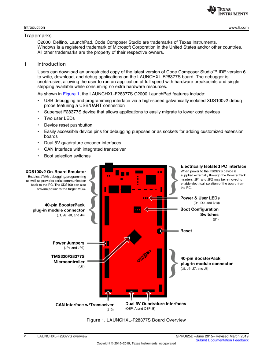
As shown in Figure 1, the LAUNCHXL-F28377S C2000 LaunchPad features include:
• USB debugging and programming interface via a high-speed galvanically isolated XDS100v2 debug
probe featuring a USB/UART connection
• Superset F28377S device that allows applications to easily migrate to lower cost devices
• Two user LEDs
• Device reset pushbutton
• Easily accessible device pins for debugging purposes or as sockets for adding customized extension
boards
• Dual 5V quadrature encoder interfaces
• CAN Interface with integrated transceiver
• Boot selection switches
Figure 1. LAUNCHXL-F28377S Board Overview
2
LAUNCHXL-F28377S overview
Copyright © 2015–2019, Texas Instruments Incorporated
SPRUI25D–June 2015–Revised March 2019
Submit Documentation Feedback
�
www.ti.com
2
Kit Contents
The LAUNCHXL-F28377S LaunchPad experimenter kit includes the following items:
• C2000 Delfino LaunchPad Board (LAUNCHXL-F28377S)
• Mini USB-B Cable, 0.5m
• Quick Start Guide
Kit Contents
2.1 Revisions
The first production revision of the LAUNCHXL-F28377S in 2016 was Revision 1.0.
All Revisions:
• Resistor R7 in the oscillator circuit is incorrectly placed or should not be installed. This resistor may
impact startup time or robustness of the clocking circuit over the full operating range of the MCU or
different physical layouts of this circuit. The probability is low that this resistor will have any impact on
the functionality of this EVM as is not intended to be operated outside of Standard Temperature and
Pressure in a lab or prototype environment. Do not use this circuit as reference. Follow the
requirements for the Oscillator schematic as documented in the MCU Datasheet.
3
Installation
The F28377S LaunchPad is supported in Code Composer Studio.
3.1 Code Composer Studio
3.1.1
Download the Required Software
Code Composer Studio IDE is available for free without any restriction when used with the XDS100 debug
probe on the C2000 LaunchPad. The software can be downloaded from the C2000 LaunchPad page at
ti.com/launchpad. At this site, you can also download a copy of controlSUITE that includes drivers,
examples, and other support software needed to get started.
3.1.2
Install the Software
Once downloaded, install Code Composer Studio and the controlSUITE package.
3.1.3
Install the Hardware
After Code Composer Studio is installed, plug the supplied USB cable into the C2000 LaunchPad board
and into an available USB port on your computer.
Windows® will automatically detect the hardware and ask you to install software drivers. Let Windows run
a search for the drivers and automatically install them. After Windows successfully installs the drivers for
the integrated XDS100v2 debug probe, your LaunchPad is now ready for use.
4
Getting Started with the LAUNCHXL-F28377S
4.1 Getting Started
The first time the LAUNCHXL-F28377S is used, a demo application automatically starts when the board is
powered from a USB host. If your board does not start the demo application, try placing S1 in the following
positions and resetting the board: UP - UP - DOWN. To start the demo, connect the LAUNCHXL-F28377S
with the included mini-USB cable to a free USB port. The demo application starts with the LEDs flashing
to show the device is active.
SPRUI25D–June 2015–Revised March 2019
Submit Documentation Feedback
Copyright © 2015–2019, Texas Instruments Incorporated
LAUNCHXL-F28377S overview
3
�
Getting Started with the LAUNCHXL-F28377S
4.2 Demo Application, ADC Sampling
www.ti.com
The LAUNCHXL-F28377S includes a pre-programmed TMS320F28377S device. When the LaunchPad is
connected via USB, the demo starts with an LED flash sequence. After a few seconds the device switches
into an ADC sample mode.
Each second the ADC is sampled and the sample data is relayed to you. If the sample is above mid-scale
(2048), the red LED will light. However, if the sample is below mid-scale the blue LED will light.
In addition to the LED display, sample information is also displayed on your PC through the USB/UART
connection. To view the UART information on your PC, first figure out the COM port associated with the
LaunchPad. To do this in Windows, right click on My Computer and click on Properties. In the dialog box
that appears, click on the Hardware tab and open Device Manager. Look for an entry under Ports (COM &
LPT) titled "USB Serial Port (COMX)", where X is a number. Remember this number for when you open a
serial terminal. The demo applications UART data was written and debugged using PuTTY, and for the
best user experience we recommend you use PuTTY to view the UART data. PuTTY can be downloaded
from the following URL:
http://www.chiark.greenend.org.uk/~sgtatham/putty/download.html
Open your serial terminal program and open the COM port you found previously in device manager with
the following settings: 115200 Baud, 8 data bits, no parity, 1 stop bit. After opening the serial port in your
serial terminal, reset the Launchpad with the reset push button and observe the serial terminal for a
surprise.
4.3 Program and Debug the ADC Sample Demo Application
The project and associated source code for the C2000 Delfino LaunchPad demo is included in the
controlSUITE software package and should automatically be found by the TI Resource Explorer in Code
Composer Studio v6. In the resource explorer, open the controlSUITE folder and then the Development
Tools entry and look for the C2000 LaunchPad line item. Expand this item and LAUNCHXL-F28377S,
then select the LaunchPad Demo Application. Follow the steps in the main pane of the resource explorer
to import, build, debug, and run this application.
4.4 Using other Examples
Including the LaunchPad demo example described above, controlSUITE provides many examples
demonstrating a majority of the features of the F2837x MCU. Most examples are configured by default to
use the other hardware which has a different on-board clocking circuit. As such, some examples may not
work as intended without minor modification. To make this easier on the designer, compiler switch has
been added to automatically pick the proper clock configuration based on adding "_LAUNCHXL_F28377S"
as a predefined symbol in the project properties. Refer to for more information on how and where to define
this symbol.
4
LAUNCHXL-F28377S overview
Copyright © 2015–2019, Texas Instruments Incorporated
SPRUI25D–June 2015–Revised March 2019
Submit Documentation Feedback
�
www.ti.com
5
Hardware Configuration
The F28377S LaunchPad provides users with several options on how to configure the board.
Hardware Configuration
5.1 ADC Resolution
While the F28377S device has a 16 bit ADC, this development kit has been designed to use the ADC in
its 12-bit mode. The user can use the ADC in its 16-bit mode by driving the proper differential signals into
the ADC. Performance will not be on par with the data sheet [1] due to the reference circuitry being
designed to match the ADC's 12-bit mode.
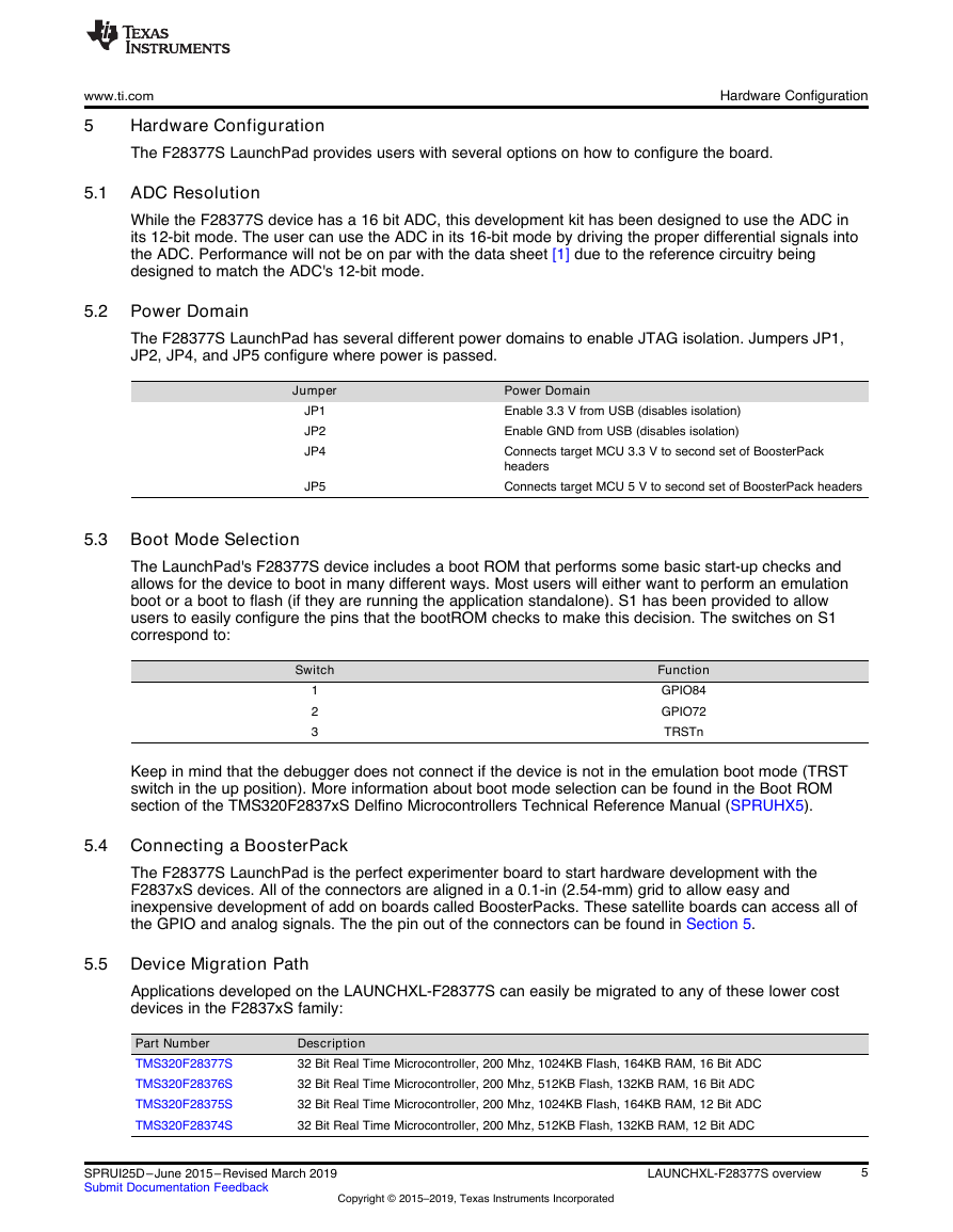
5.2 Power Domain
The F28377S LaunchPad has several different power domains to enable JTAG isolation. Jumpers JP1,
JP2, JP4, and JP5 configure where power is passed.
Jumper
JP1
JP2
JP4
JP5
Power Domain
Enable 3.3 V from USB (disables isolation)
Enable GND from USB (disables isolation)
Connects target MCU 3.3 V to second set of BoosterPack
headers
Connects target MCU 5 V to second set of BoosterPack headers
5.3 Boot Mode Selection
The LaunchPad's F28377S device includes a boot ROM that performs some basic start-up checks and
allows for the device to boot in many different ways. Most users will either want to perform an emulation
boot or a boot to flash (if they are running the application standalone). S1 has been provided to allow
users to easily configure the pins that the bootROM checks to make this decision. The switches on S1
correspond to:
Switch
1
2
3
Function
GPIO84
GPIO72
TRSTn
Keep in mind that the debugger does not connect if the device is not in the emulation boot mode (TRST
switch in the up position). More information about boot mode selection can be found in the Boot ROM
section of the TMS320F2837xS Delfino Microcontrollers Technical Reference Manual (SPRUHX5).
5.4 Connecting a BoosterPack
The F28377S LaunchPad is the perfect experimenter board to start hardware development with the
F2837xS devices. All of the connectors are aligned in a 0.1-in (2.54-mm) grid to allow easy and
inexpensive development of add on boards called BoosterPacks. These satellite boards can access all of
the GPIO and analog signals. The the pin out of the connectors can be found in Section 5.
5.5 Device Migration Path
Applications developed on the LAUNCHXL-F28377S can easily be migrated to any of these lower cost
devices in the F2837xS family:
Part Number
TMS320F28377S
TMS320F28376S
TMS320F28375S
TMS320F28374S
Description
32 Bit Real Time Microcontroller, 200 Mhz, 1024KB Flash, 164KB RAM, 16 Bit ADC
32 Bit Real Time Microcontroller, 200 Mhz, 512KB Flash, 132KB RAM, 16 Bit ADC
32 Bit Real Time Microcontroller, 200 Mhz, 1024KB Flash, 164KB RAM, 12 Bit ADC
32 Bit Real Time Microcontroller, 200 Mhz, 512KB Flash, 132KB RAM, 12 Bit ADC
SPRUI25D–June 2015–Revised March 2019
Submit Documentation Feedback
Copyright © 2015–2019, Texas Instruments Incorporated
LAUNCHXL-F28377S overview
5
�
LAUNCHXL-F28377S Hardware
6
LAUNCHXL-F28377S Hardware
6.1 Device Pin Out
www.ti.com
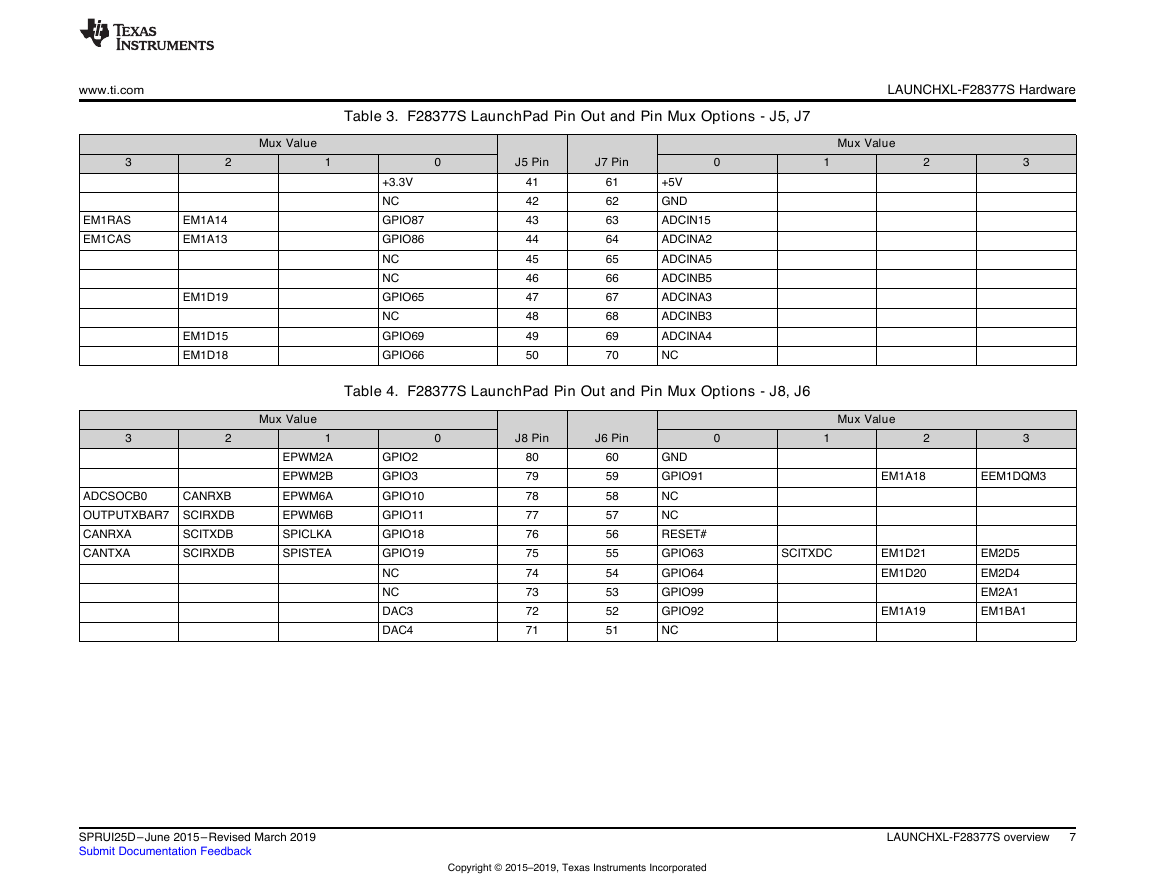
..Table 1 through Table 4 lists the pin out and pin mux options for the C2000 LaunchPad. Additional muxing options are available and can be
found in the TMS320F2837xS Delfino Microcontrollers Data Manual (SPRS881).
Table 1. F28377S LaunchPad Pin Out and Pin Mux Options - J1, J3
Mux Value
1
2
0
J1 Pin
J3 Pin
0
Mux Value
1
2
3
3
3
EM1DQM2
EM1DQM1
EM2D8
EM2D7
EM1D13
EM1A17
EM1A16
EM1A3
EM1D24
EM1D23
MCLKRB
MFSRB
Mux Value
1
EPWM7A
EPWM7B
EPWM8A
EPWM8B
SPISIMOA
SPISOMIA
EQEP1A
EQEP1B
3
2
CANTXB
MDXB
CANRXB
MDRB
SCITXDB
MCLKXB
MFSXB
SCIRXDB
OUTPUTXBAR7 CANTXB
OUTPUTXBAR8 CANRXB
CANTXB
CANRXB
MDXA
MDRA
+3.3 V
GPIO71
GPIO90
GPIO89
GPIO41
NC
GPIO60
GPIO61
GPIO43
GPIO42
1
2
3
4
5
6
7
8
9
10
21
22
23
24
25
26
27
28
29
30
+5 V
GND
ADCIN14
ADCINB1
ADCINB4
ADCINB2
ADCINA0
ADCINB0
ADCINA1
NC
Table 2. F28377S LaunchPad Pin Out and Pin Mux Options - J4, J2
0
J4 Pin
J2 Pin
0
Mux Value
1
2
GPIO12
GPIO13
GPIO14
GPIO15
GPIO16
GPIO17
GPIO20
GPIO21
DAC1
DAC2
40
39
38
37
36
35
34
33
32
31
20
19
18
17
16
15
14
13
12
11
GND
GPIO4
GPIO62
NC
RESET#
GPIO58
GPIO59
GPIO72
GPIO73
GPIO78
EPWM3A
SCIRXDC
MCLKRA
MFSRA
EM1D22
EM2D6
EM1D26
EM1D25
EM1D12
EM1D11
EM1D6
EM2D10
EM2D9
XCLKOUT
6
LAUNCHXL-F28377S overview
Copyright © 2015–2019, Texas Instruments Incorporated
SPRUI25D–June 2015–Revised March 2019
Submit Documentation Feedback
�
www.ti.com
LAUNCHXL-F28377S Hardware
Table 3. F28377S LaunchPad Pin Out and Pin Mux Options - J5, J7
3
Mux Value
1
2
0
J5 Pin
J7 Pin
0
Mux Value
1
2
+3.3V
NC
GPIO87
GPIO86
NC
NC
GPIO65
NC
GPIO69
GPIO66
41
42
43
44
45
46
47
48
49
50
61
62
63
64
65
66
67
68
69
70
+5V
GND
ADCIN15
ADCINA2
ADCINA5
ADCINB5
ADCINA3
ADCINB3
ADCINA4
NC
Table 4. F28377S LaunchPad Pin Out and Pin Mux Options - J8, J6
0
J8 Pin
J6 Pin
0
Mux Value
1
2
3
3
EM1RAS
EM1CAS
EM1A14
EM1A13
EM1D19
EM1D15
EM1D18
3
2
ADCSOCB0
CANRXB
OUTPUTXBAR7 SCIRXDB
SCITXDB
CANRXA
CANTXA
SCIRXDB
Mux Value
1
EPWM2A
EPWM2B
EPWM6A
EPWM6B
SPICLKA
SPISTEA
GPIO2
GPIO3
GPIO10
GPIO11
GPIO18
GPIO19
NC
NC
DAC3
DAC4
80
79
78
77
76
75
74
73
72
71
60
59
58
57
56
55
54
53
52
51
GND
GPIO91
NC
NC
RESET#
GPIO63
GPIO64
GPIO99
GPIO92
NC
EM1A18
EEM1DQM3
SCITXDC
EM1D21
EM1D20
EM1A19
EM2D5
EM2D4
EM2A1
EM1BA1
SPRUI25D–June 2015–Revised March 2019
Submit Documentation Feedback
Copyright © 2015–2019, Texas Instruments Incorporated
LAUNCHXL-F28377S overview
7
�
LAUNCHXL-F28377S Hardware
6.2 Schematics
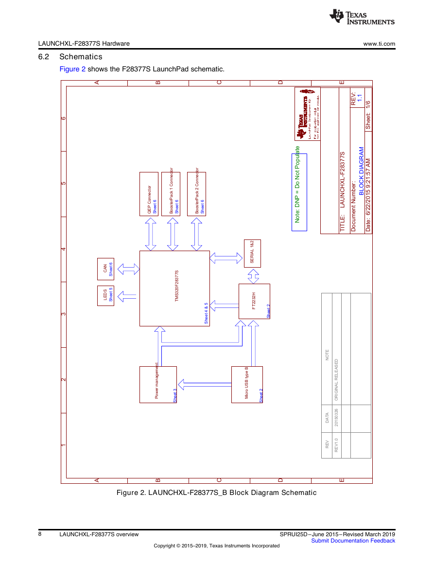
Figure 2 shows the F28377S LaunchPad schematic.
www.ti.com
Figure 2. LAUNCHXL-F28377S_B Block Diagram Schematic
8
LAUNCHXL-F28377S overview
Copyright © 2015–2019, Texas Instruments Incorporated
SPRUI25D–June 2015–Revised March 2019
Submit Documentation Feedback
1.1BLOCKDIAGRAMSheet 2Sheet 3Sheet 4 & 5Sheet 2Sheet 6Sheet 6Sheet 6Sheet6Sheet 5REVDATANOTEREV1.020150326ORIGINALRELEASEDPower managementMicro USB type BFT2232HTMS320F28377SBoosterPack 1 ConnectorLEDSCANSERIAL1&2BoosterPack2 ConnectorQEPConnectorABCDEABCDE123456Date:6/22/20159:21:57AMSheet:1/6REV:TITLE:DocumentNumber:LAUNCHXL-F28377SNote:DNP=DoNot Populate�





 2023年江西萍乡中考道德与法治真题及答案.doc
 2012年重庆南川中考生物真题及答案.doc
 2013年江西师范大学地理学综合及文艺理论基础考研真题.doc
 2020年四川甘孜小升初语文真题及答案I卷.doc
 2020年注册岩土工程师专业基础考试真题及答案.doc
 2023-2024学年福建省厦门市九年级上学期数学月考试题及答案.doc
 2021-2022学年辽宁省沈阳市大东区九年级上学期语文期末试题及答案.doc
 2022-2023学年北京东城区初三第一学期物理期末试卷及答案.doc
 2018上半年江西教师资格初中地理学科知识与教学能力真题及答案.doc
 2012年河北国家公务员申论考试真题及答案-省级.doc
 2020-2021学年江苏省扬州市江都区邵樊片九年级上学期数学第一次质量检测试题及答案.doc
 2022下半年黑龙江教师资格证中学综合素质真题及答案.doc