PEX 8619BA Base Board RDK
Hardware Reference Manual
Version 1.0
April 2009
Website: www.plxtech.com
Technical Support: www.plxtech.com/support
Copyright © 2009 by PLX Technology, Inc. All Rights Reserved – Version 1.0
April 15, 2009
�
© 2009 PLX Technology, Inc. All rights reserved.
PLX Technology, Inc. retains the right to make changes to this product at any time, without notice. Products may have minor
variations to this publication, known as errata. PLX assumes no liability whatsoever, including infringement of any patent or
copyright, for sale and use of PLX products.
PLX Technology and the PLX logo are registered trademarks of PLX Technology, Inc.
Other brands and names are the property of their respective owners.
Document Number: PEX8619BA-Base Board RDK-HRM-1.0
April 15, 2009
PEX 8619BA Base Board RDK Hardware Reference Manual – Version 1.0
Copyright © 2009 by PLX Technology, Inc. All rights reserved
2
�
PREFACE
NOTICE
This document contains PLX Confidential and Proprietary information. The contents of this document may not be
copied nor duplicated in any form, in whole or in part, without prior written consent from PLX Technology, Inc.
PLX provides the information and data included in this document for your benefit, but it is not possible to entirely
verify and test all the information, in all circumstances, particularly information relating to non-PLX manufactured
products. PLX makes neither warranty nor representation relating to the quality, content, or adequacy of this
information. The information in this document is subject to change without notice. Although every effort has been
made to ensure the accuracy of this manual, PLX shall not be liable for any errors, incidental, or consequential
damages in connection with the furnishing, performance, or use of this manual or examples herein. PLX assumes
no responsibility for damage or loss resulting from the use of this manual, for loss or claims by third parties, which
may arise through the use of the RDK, or for any damage or loss caused by deletion of data as a result of
malfunction or repair.
ABOUT THIS MANUAL
This document describes the PLX PEX 8619BA-Base Board RDK, a Rapid Development Kit, from a hardware
perspective. It contains a description of all major functional circuit blocks on the board and also is a reference for
the creation of software for this product. This manual also includes complete schematics and bill of materials.
REVISION HISTORY
Date
Version
Comments
April 2009
1.0
Initial Release
PEX 8619BA Base Board RDK Hardware Reference Manual – Version 1.0
Copyright © 2009 by PLX Technology, Inc. All rights reserved
i
�
1.1
1.2
3.1
3.2
3.10.1
3.10.2
3.2.1
3.2.2
3.2.3
3.2.4
3.2.5
CONTENTS
NOTICE ......................................................................................................................................................................... i
ABOUT THIS MANUAL ..................................................................................................................................................... i
REVISION HISTORY .................................................................................................................................................... i
1. General Information ........................................................................................................................................... 1
PEX 8619 Features ................................................................................................................................... 1
PEX 8619BA-BB RDK Features ................................................................................................................ 3
2. System Architecture ........................................................................................................................................... 4
3. Hardware Architecture ....................................................................................................................................... 5
PEX 8619 ................................................................................................................................................... 5
PCI Express Interfaces .............................................................................................................................. 5
RDK Configuration Modules and Their Receptacles ......................................................................... 5
PCI Express Lane 0 to Lane 3 ........................................................................................................... 6
PCI Express Lane 4 to Lane 7 ........................................................................................................... 6
PCI Express Lane 8 to Lane 11 ......................................................................................................... 7
PCI Express lane 12 to lane 15 ......................................................................................................... 8
Reference Clock Circuits ........................................................................................................................... 8
3.3
Reset Circuits ............................................................................................................................................ 9
3.4
Serial Hot-Plug (SHP) Controller Circuits ................................................................................................ 10
3.5
Serial EEPROM ....................................................................................................................................... 11
3.6
I2C Interface ............................................................................................................................................. 11
3.7
Power Distribution Circuits ....................................................................................................................... 11
3.8
FPGA Interface ........................................................................................................................................ 12
3.9
3.10 LED and 7-Segment Displays ................................................................................................................. 13
LED Indicators ................................................................................................................................. 13
7-Segment Displays ......................................................................................................................... 14
3.11 GPIO Pins ................................................................................................................................................ 15
3.12 Reserved Pins ......................................................................................................................................... 15
4. On-Board Connectors, Switches, and Jumpers ............................................................................................... 16
DIP Switches ........................................................................................................................................... 16
Dip Switch Group 1 .......................................................................................................................... 16
Dip Switch Group 2 .......................................................................................................................... 17
Dip Switch Group 3 .......................................................................................................................... 19
Push-Button Switches .............................................................................................................................. 20
Manual Reset# (S1) ......................................................................................................................... 20
FPGA Manual Reset# (S2) .............................................................................................................. 20
Serial Hot-Plug Controller Attention Button (S3) ............................................................................. 21
Connectors and Headers ......................................................................................................................... 21
ATX Peripheral Power Connectors (J1-J4 & J7-J8) ........................................................................ 21
4.3.1
x4 PCI Express External Cable Connectors (J5 & J6) .................................................................... 21
4.3.2
ATX Main Power Connector (J9) ..................................................................................................... 22
4.3.3
ATX +12V Power Connector(J10) ................................................................................................... 22
4.3.4
Xilinx JTAG Connector (J12) ........................................................................................................... 22
4.3.5
Xilinx Mode Setting Header (J13) .................................................................................................... 23
4.3.6
PEX 8619 JTAG Header (JP3) ........................................................................................................ 23
4.3.7
SMBus Header (JP5) ....................................................................................................................... 23
4.3.8
4.3.9
PCI Express x8 Midbus Probe Footprint (JP6) ................................................................................ 23
4.3.10 PEX 8619 I2C Port (JP8) ................................................................................................................. 24
4.3.11 Debug Signal Header (JP9 & JP11) ................................................................................................ 24
4.3.12 Debug Input Header (JP10) ............................................................................................................. 26
4.3.13 Reference Clock Header (JP100) .................................................................................................... 26
5. RDK Port Configurations .................................................................................................................................. 27
6. Bill of Materials/ Schematics ............................................................................................................................ 33
4.1.1
4.1.2
4.1.3
4.2.1
4.2.2
4.2.3
4.1
4.2
4.3
PEX 8619BA Base Board RDK Hardware Reference Manual – Version 1.0
Copyright © 2009 by PLX Technology, Inc. All rights reserved
ii
�
FIGURES
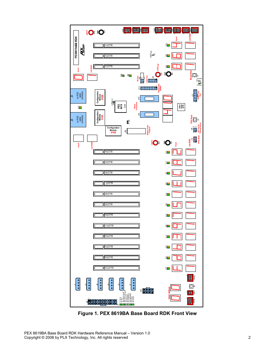
Figure 1. PEX 8619BA Base Board RDK Front View ................................................................................................ 2
Figure 2. Connecting The RDK to a PC with x1 or x4 link ......................................................................................... 4
Figure 3. Connecting the RDK to a PC with x8 link ................................................................................................... 4
Figure 4. Lanes 0-3 Hardware Connections on the RDK .......................................................................................... 6
Figure 5. Lanes 4-7 Hardware Connections on the RDK .......................................................................................... 7
Figure 6. Lanes 8-11 Hardware Connections on the RDK ........................................................................................ 7
Figure 7. Lanes 12 – 15 Hardware Connections on the RDK ................................................................................... 8
Figure 8. RDK Reference Clock Circuits ................................................................................................................... 9
Figure 9. RDK Reset Circuits .................................................................................................................................... 9
Figure 10. SERIAL HOT-PLUG Circuits .................................................................................................................. 10
Figure 11. RDK ATX Power Connectors ................................................................................................................. 11
Figure 12. RDK Power Distribution Circuits ............................................................................................................ 12
Figure 13. FPGA Interface on RDK ......................................................................................................................... 13
Figure 14. RDK Dip Switch Groups ......................................................................................................................... 16
Figure 15. Group1 of Switches ................................................................................................................................ 16
Figure 16. Group 2 of Dipswitches .......................................................................................................................... 17
Figure 17. Group 3 of Dip Switches ......................................................................................................................... 19
Figure 18. x1 upstream and 15x1 downstream (PCFG=0000) ............................................................................... 27
Figure 19. x4 upstream 12x1 downstream (PCFG=0001) ...................................................................................... 28
Figure 20. x4 upstream, 1x4 and 8x1 downstream (PCFG=0010) .......................................................................... 29
Figure 21. x4 upstream, 2x4 and 4x1 downstream (PCFG=0011) .......................................................................... 30
Figure 22. x8 upstream, 8x1 downstream (PCFG=0101) ....................................................................................... 31
Figure 23. x8 upstream, 1x4 and 4x1 downstream (PCFG=0110) .......................................................................... 32
TABLES
Table 1. Port Configurations Supported by the RDK ................................................................................................. 5
Table 2. RDK LED Indicator descriptions ................................................................................................................ 13
Table 3. RDK 7-Segment Display Functions ........................................................................................................... 14
Table 4. Strap_Reserved Pin Connections ............................................................................................................. 15
Table 5. Functional Description of Group 1 Dip Switches ....................................................................................... 17
Table 6. Functional Description of Group 2 Dip Switches ....................................................................................... 18
Table 7. Port Configurations use Dipswitch SW2 .................................................................................................... 19
Table 8. Functional Descriptions of SW3, SW6, SW13-SW14 ............................................................................... 20
Table 9. Signal Names of J1-J4 & J7-J8 ................................................................................................................. 21
Table 10. Signal Names of J5 and J6 ...................................................................................................................... 21
Table 11. Signal Names of J9 ................................................................................................................................. 22
Table 12. Signal Names of J10 ............................................................................................................................... 22
Table 13. Signal Names of J12 ............................................................................................................................... 22
Table 14. Signal Names of J13 ............................................................................................................................... 23
Table 15. Pin assignment of JP3 ............................................................................................................................. 23
Table 16. Signal Names of JP5 ............................................................................................................................... 23
Table 17. Signal Names of JP6 ............................................................................................................................... 23
Table 18. Pin assignment of JP8 ............................................................................................................................. 24
Table 19. Pin assignment of JP9 & JP11 ................................................................................................................ 24
Table 20. Pin assignment of JP10 ........................................................................................................................... 26
Table 21. Pin assignment of JP100 ......................................................................................................................... 26
PEX 8619BA Base Board RDK Hardware Reference Manual – Version 1.0
Copyright © 2009 by PLX Technology, Inc. All rights reserved
iii
�
1. General Information
The PLX PEX 8619BA Base Board RDK is a Rapid Development Kit based on the PEX 8619, a 16-lane, 16-port
PCI Express switch based in the PCI Express Specification rev 2.0 with SerDes capable of running at 5 GT/s. The
PEX 8619BA Base Board RDK provides a complete hardware and software development platform that facilitates
getting designs up and running quickly, lowering risk and reducing time-to-market. This RDK consists a base
board containing three hardware configuration Modules, a PCI Express cable adapter board that plugs into the
host system, and up to two x4 PCI Express cables that used to connect the RDK to the cable adapter. This
manual primarily focuses on the PEX 8619BA Base Board RDK, and its use with other parts to demonstrate the
various functions of PEX 8619 chip. Figure 1 provides a top view (component side) of the PEX 8619BA Base
Board RDK.
1.1
PEX 8619 Features
• 16-lane, 16-port PCI Express Gen 2 switch with integrated on-chip SerDes
• 160 GT/s aggregate bandwidth (5.0 GT/s/Lane x 16 Lanes x 2 (full duplex))
• 19mm2 324-ball Plastic Ball Grid Array (PBGA) package
• Typical Power – 2.2W
• Cut-Thru packet latency of less than 160ns
• Low power SerDes (under 90mW per lane)
• Fully non-blocking switch architecture
• Flexible port configuration
• Flexible device configuration
o 16 flexible and configurable ports (x1,x4 or x8), x2 is also supported
o Configurable via serial EEPROM, I2C, hardware strapping, or by the host
• Maximum packet payload size of 2,048 bytes
• Designate any Port as the Upstream Port (Port 0 is recommended)
• Dynamic Buffer Pool Architecture
• Read Pacing (allows user to throttle Read requests from Downstream Ports to allow for more efficient
performance)
Integrated Direct Memory Access (DMA) engine
• Dual-Casting (enhances performance by sending date from one ingress port to two egress ports)
•
• Dynamic speed (2.5 GT/s or 5.0 GT/s) negotiation
• Dynamic link-width negotiation (automatically negotiates down to optimal link-width based on traffic
density)
• Lane and polarity reversal
• Non-Transparent Bridging support
o Enables Dual-Host, Host-Failover applications
• Conventional PCI-compatible Link Power Management states – L0, L0s, L1, L2/L3 Ready, and L3 (with
Vaux not supported)
• Conventional PCI-compatible Device Power Management states – D0 and D3hot
• Active State Power Management
• Spread-Spectrum Clock Isolation (Dual-clock Domain)
• Quality of Service (QoS)
• Reliability, Availability, Serviceability (RAS) features
Weighted Round-Robin Port and Virtual Channel arbitration
o Two Virtual Channels (VC0 and VC1) and Eight Traffic classes (TC)
o
o All ports are Hot-Plug capable through I2C (Serial Hot-Plug Controller on every port)
o Advanced Error Reporting capability
o Performance Monitoring
Per-Port Payload and Header Counters
Per-traffic type (write, Read, Completion) Counters
o JTAG AC/DC boundary scan
o 16 Lane status balls (PEX_LANE_GOOD[15:0]#)
o 32 GPIO balls (GPIO[31:0]
PEX 8619BA Base Board RDK Hardware Reference Manual – Version 1.0
Copyright © 2009 by PLX Technology, Inc. All rights reserved
1
�
Figure 1. PEX 8619BA Base Board RDK Front View
PEX 8619BA Base Board RDK Hardware Reference Manual – Version 1.0
Copyright © 2008 by PLX Technology, Inc. All rights reserved
2
�
•
INTA# (PEX_INTA#) and FATAL ERROR (FATAL_ERR#) (Conventional PCI SERR# equivalent) ball
support
• Compliant to the following specifications:
o PCI Local Bus Specification, Revision 3.0 (PCI r3.0)
o PCI Bus Power Management Interface Specification, Revision 1.2 (PCI Power Mgmt. r1.2)
o PCI to PCI Bridge Architecture Specification, Revision 1.2 (PCI-to-PCI Bridge r1.2)
o PCI Express Base Specification, Revision 1.1 (PCI Express Base r1.1)
o PCI Express Base Specification, Revision 2.0 (PCI Express Base r2.0)
o
o
o
o
o The I2C-Bus Specification, Version 2.1 (I2C Bus v2.1)
IEEE Standard 1149.1-1990, IEEE Standard Test Access Port and Boundary-Scan Architecture,
1990 (IEEE Standard 1149.1-1990)
IEEE Standard 1149.1a-1993, IEEE Standard Test Access Port and Boundary-Scan Architecture
IEEE Standard 1149.1-1994, Specifications for Vendor-Specific Extensions
IEEE Standard 1149.6-2003, IEEE Standard Test Access Port and Boundary-Scan Architecture
Extensions (IEEE Standard 1149.6-2003)
1.2
PEX 8619BA-BB RDK Features
• PLX PEX 8619 PCI Express switch in a 324-ball Plastic BGA package
• Based on PCI Express Card Electromechanical (CEM) Specification 2.0 and PCI Express External
• Supports up to 6 different port configurations with x4 PCI Express cable connection(s) to the upstream
Cabling Specification 1.0
PC
In system programmable Serial EEPROM (2.5V)
• Non-Transparent Bridging support
• One x8 Gen 2 Midbus probe footprint for upper 8 lanes of PCI Express signal probing for the chip
• PCI Express RefClk Circuits supports Spread-Spectrum Clock Isolation
• Serial Hot-Plug circuits on one PCI Express card edge connector
•
• A standard 2x2 header provides the I2C interface to an I2C master
• DIP switches for port configuration, upstream port or NT port select and I2C address settings
• Manual push-button PERST# capability
• Up to sixteen dual color LEDs for visual inspection of link speed and status
• 7-Segment displays for port numbers and link width
• Up to 3-digit display for junction temperature of PEX 8619
• Voltage level monitoring circuit for 1.0V and 2.5V power to the PEX 8619
PEX 8619BA Base Board RDK Hardware Reference Manual – Version 1.0
Copyright © 2008 by PLX Technology, Inc. All rights reserved
3
�




 2023年江西萍乡中考道德与法治真题及答案.doc
 2012年重庆南川中考生物真题及答案.doc
 2013年江西师范大学地理学综合及文艺理论基础考研真题.doc
 2020年四川甘孜小升初语文真题及答案I卷.doc
 2020年注册岩土工程师专业基础考试真题及答案.doc
 2023-2024学年福建省厦门市九年级上学期数学月考试题及答案.doc
 2021-2022学年辽宁省沈阳市大东区九年级上学期语文期末试题及答案.doc
 2022-2023学年北京东城区初三第一学期物理期末试卷及答案.doc
 2018上半年江西教师资格初中地理学科知识与教学能力真题及答案.doc
 2012年河北国家公务员申论考试真题及答案-省级.doc
 2020-2021学年江苏省扬州市江都区邵樊片九年级上学期数学第一次质量检测试题及答案.doc
 2022下半年黑龙江教师资格证中学综合素质真题及答案.doc