Open Access Library Journal
2018, Volume 5, e4295
ISSN Online: 2333-9721
ISSN Print: 2333-9705
Study on Braking Energy
Recovery of Four Wheel Drive
Electric Vehicle Based on
Driving Intention Recognition
Feihu Xuan, Huanhuan Zhang, Wenwen Xiao
College of Automotive Engineering, Shanghai University of Engineering Science, Shanghai, China
How to cite this paper: Xuan, F.H., Zhang,
H.H. and Xiao, W.W. (2018) Study on
Braking Energy Recovery of Four Wheel
Drive Electric Vehicle Based on Driving
Intention Recognition. Open Access Library
Journal, 5: e4295.
https://doi.org/10.4236/oalib.1104295
Received: December 28, 2017
Accepted: January 21, 2018
Published: January 24, 2018
Copyright © 2018 by authors and Open
Access Library Inc.
This work is licensed under the Creative
Commons Attribution International
License (CC BY 4.0).
http://creativecommons.org/licenses/by/4.0/
Open Access
Abstract
To judge the driver’s driving intention can effectively improve the car braking
energy recovery. Aiming at the problem of braking energy recovery of four
wheel drives electric vehicle, combined with the main restrictive conditions of
ECE regulations, motor characteristics and battery SOC, a braking force distri-
bution strategy for different braking intention is established. The MATLAB/
Simulink platform is used for modeling and simulation to verify the effective-
ness of the braking energy recovery strategy, and verify the compliance of the
braking strategy through the braking distance under the initial braking speed
specified in the national standard. The results show that the fuzzy recognition
model can accurately identify the various brake driving intentions, according
to different driving intention under the brake, braking force distribution
strategy are established, which is effective in the initial braking speed under
different braking distance is also in line with national standards.
Subject Areas
Mechanical, Engineering, Automata
Keywords
Driving Intention, Energy Recovery, Fuzzy Control, Four Wheel Drive
1. Introduction
The shortage of oil resources and environmental pollution has seriously affected
people’s lives. Therefore, the attention of the whole society and the government
DOI: 10.4236/oalib.1104295 Jan. 24, 2018
1
Open Access Library Journal
�
F. H. Xuan et al.
has been aroused by this kind of environment [1]. The four wheel hub motor
independent drive electric vehicle has gained the attention of experts and scho-
lars at home and abroad because of its advantages of simplified traditional sys-
tem, saving space and flexible motor control, compared with the advantages of
ordinary electric vehicle, and they achieved fruitful research results through ef-
forts. In the key technology of the electric vehicle, the regenerative braking
technology can reclaim the braking energy and increase the driving range of the
electric vehicle. The electric vehicle with the braking energy recovery function
also has the motor brake system and the mechanical brake system. The reasona-
ble distribution of the mechanical brake system and motor regenerative braking
system can guarantee the automobile brake under the condition of a large num-
ber of braking energy recoveries, therefore, introducing the driving intention
through the judgment and the purpose of the driver to judge can identify a va-
riety of braking intention mode, and then matching between mechanical braking
force and braking force for various motor’s braking mode, the idea of this study
is on the basis of this [2].
2. Research on Driving Intention Recognition
In this paper, the acceleration pedals displacement, brake pedal displacement,
brake pedal displacement rate, speed, and driving intention identification para-
meters is used in this paper. According to the current vehicle speed, the braking
intention can be divided into high-speed braking mode, medium speed braking
mode and low speed braking mode. Then the three braking modes are divided
into emergency braking mode, general braking mode and slow braking mode
respectively. There are three kinds of high speed braking mode: high speed
emergency braking mode, high speed general braking mode and high speed flat
brakes mode. There are also three kinds of medium speed braking mode: me-
dium speed emergency brake mode, medium speed general brake mode and me-
dium speed slow braking mode. In low speed braking mode, the classification of
brake conditions is not very obvious because of the high or low braking strength,
so it is set as a mode, that is, low speed braking mode [3].
The process of braking intention recognition is as follows: firstly, by judging
the vehicle speed is in high speed, medium speed or low speed, and then through
the displacement of brake pedals and the accelerator pedal position if there is a
change to determine whether the driver braking operation, if the acceleration
pedal and brake pedal has changed, the judgment at this time for the wrong op-
eration mode wrong operation mode after the action requires specific judgment
according to the speed. If the speed is in the low speed mode at this time, it is
judged to be the acceleration mode. If the speed is in the middle and high speed
mode [4], the braking mode is judged, and the emergency braking is carried out.
If judged to be in the braking mode at this time, according to the change rate of
accelerator pedal and accelerator pedal, we can judge whether the vehicle is in an
emergency braking state, a general braking state or a slow braking state mode [5].
2
Open Access Library Journal
DOI: 10.4236/oalib.1104295
�
F. H. Xuan et al.
3. Research on Regenerative Braking Control
3.1. Restraint Condition Analysis of Regenerative Braking of
Wheel Motor
1) ECE regulation
2) In order to ensure the directional stability and sufficient braking efficiency
of brake, the ECE R13 brake regulations formulated by the European Economic
Commission of the United Nations put forward a clear request for the braking
force of front axle and rear wheel brake of double axle vehicle. Provisions of the
industry standard ZBT 24007-1989 in our country have made similar require-
ments, regulations for all kinds of vehicles: = 0.2 ~ 0.8, brake strength, vehicles
under various loading conditions, the adhesion coefficient curve in the rear axle
utilization adhesion coefficient curve using the front axle for car, brake strength
in 0.3 ~ 0.4 between the rear axle the adhesion coefficient curve does not exceed
the line conditions, allowing the rear axle utilization adhesion coefficient curve
before and after using the above adhesion coefficient curve.
3) The limit of the peak torque of the wheel motor
4) During the braking energy recovery process of the four wheel hub motor
driven electric vehicle, the motor cannot be charged without restriction due to
the limitation of the SOC value of the battery. However, the braking force re-
quired by automobile brake is greater than that of the maximum torque of the
hub motor, so that the braking force of the hub motor cannot exceed the peak
torque of the motor itself. By comprehensive consideration, the maximum
braking force of the motor should be the minimum between two cases.
5) Battery constraints
6) The battery used in this paper is lithium battery. When braking, the power
generated by the hub motor is less than the charging efficiency of the rechargea-
ble battery, so as to avoid damaging the battery. At the same time, check the
battery SOC value before charging. Only when the SOC value of the battery is
less than 0.94, can it be charged. When the SOC value of the battery is greater
than 0.94, it cannot be charged.
3.2. Analysis of Regenerative Braking Strategy
When the four wheel hub motor driven electric vehicle carries out the braking
energy recovery, the braking force distribution will be maximized under the
premise of ensuring driving safety and the braking energy is maximized. The
distribution of braking force mainly includes two aspects, one is the distribution
of braking force on the front and rear axle, the other is the distribution between
motor braking force and mechanical braking force.
By car theory, the front and rear wheel and lock when curves of front and rear
wheel brake force is the ideal of the front and rear brake force distribution curve,
referred to as curve.
The dynamic relationship between the front and back axes of the full ideal
braking force distribution is as follows:
3
Open Access Library Journal
DOI: 10.4236/oalib.1104295
�
F. H. Xuan et al.
F
2
µ
=
1
2
G
h
g
2
b
+
h
4
g
G
F
1
µ
−
Gb
h
g
+
2
F
1
µ
(3-1)
1Fµ Braking force for front wheel brake; b for the distance between the center
gh
line of the car’s center of mass and the rear axle; G for car gravity;
is the height of the car’s center of mass;
for automobile speed reduction;
2Fµ for brake force of rear wheel brake.
The distribution strategy of this paper is based on the principle that the brak-
ing energy can be recovered as much as possible under the premise of ensuring
the safety of the brake.
u
d
t
d
Through the fuzzy recognition model can be identified at this time at the car
braking mode: high speed high speed braking emergency braking mode, general
mode, high speed, medium speed smooth braking mode in emergency braking
mode, general speed braking mode, automatic mode, automatic speed and me-
dium speed flat mode. Different braking force distribution of machinery and
motor is carried out according to each braking mode. The following is the spe-
cific allocation strategy:
High speed emergency braking situation, because the motor braking force re-
sponse speed cannot meet the requirements of braking torque, and easy to trig-
ger ABS in an emergency braking situation, the brake control system complexity
increases, therefore, based on security, brake mechanical brake system of high
speed in an emergency braking situation, front and rear wheel follow the front
and rear wheel braking force distribution of braking force distribution coefficient.
In the case of high speed general braking, the total braking force required in
high speed braking is slightly smaller than that in the case of high speed emer-
gency braking. At this point, the safety factors are still very heavy, and the brak-
ing energy recovery is properly carried out. Therefore, the mechanical braking
force and the motor braking force are braking at the same time, the braking
force is greater than the motor braking force, and the braking force of the motor
is not at the maximum value state. At this time, the braking force distribution
coefficient of the front and rear wheels brakes still follows the mixed braking
force.
High speed smooth braking, high speed compared to the normal braking con-
dition, the smaller the total braking force needed at this time, in view of the
braking speed, the safety factor is more important, and considering the braking
energy recovery, while still using mechanical braking force and braking force
and braking motor, but compared to the general high speed braking. Mechanical
braking force to continue to reduce the motor braking force continues to in-
crease. And the overall braking force still follows the braking force distribution
coefficient of the front and back brakes.
For medium speed emergency braking, considering the safety consideration,
mechanical braking force is still used. Mechanical braking force follows the
4
Open Access Library Journal
DOI: 10.4236/oalib.1104295
�
F. H. Xuan et al.
brake force distribution coefficient of front and rear brake.
Medium speed general braking, medium speed and slow braking, the safety of
vehicle is in a high state. At this time, considering the maximization of braking
energy recovery, settled the motor peak braking torque, the insufficient braking
force is supplemented by mechanical braking force.
In low speed mode, when the speed of the car is below 10 km/h, the mechani-
cal braking force is all adopted because the energy recovery of the motor braking
is small. The allocation of mechanical braking force distribution follows the dis-
tribution coefficient of braking force distribution of brake force 0.6.
Implementation of braking force distribution strategy in all modes before, in
order to protect the battery from being damaged, need to go through the cell
value of SOC, if SOC is greater than 0.95, the battery based on security, not in
charge, but the energy consumption brake, if the SOC value is less than 0.95 can
be charged during charging, the battery state real-time monitoring SOC value.
4 The Establishment and Analysis of the Simulation Model
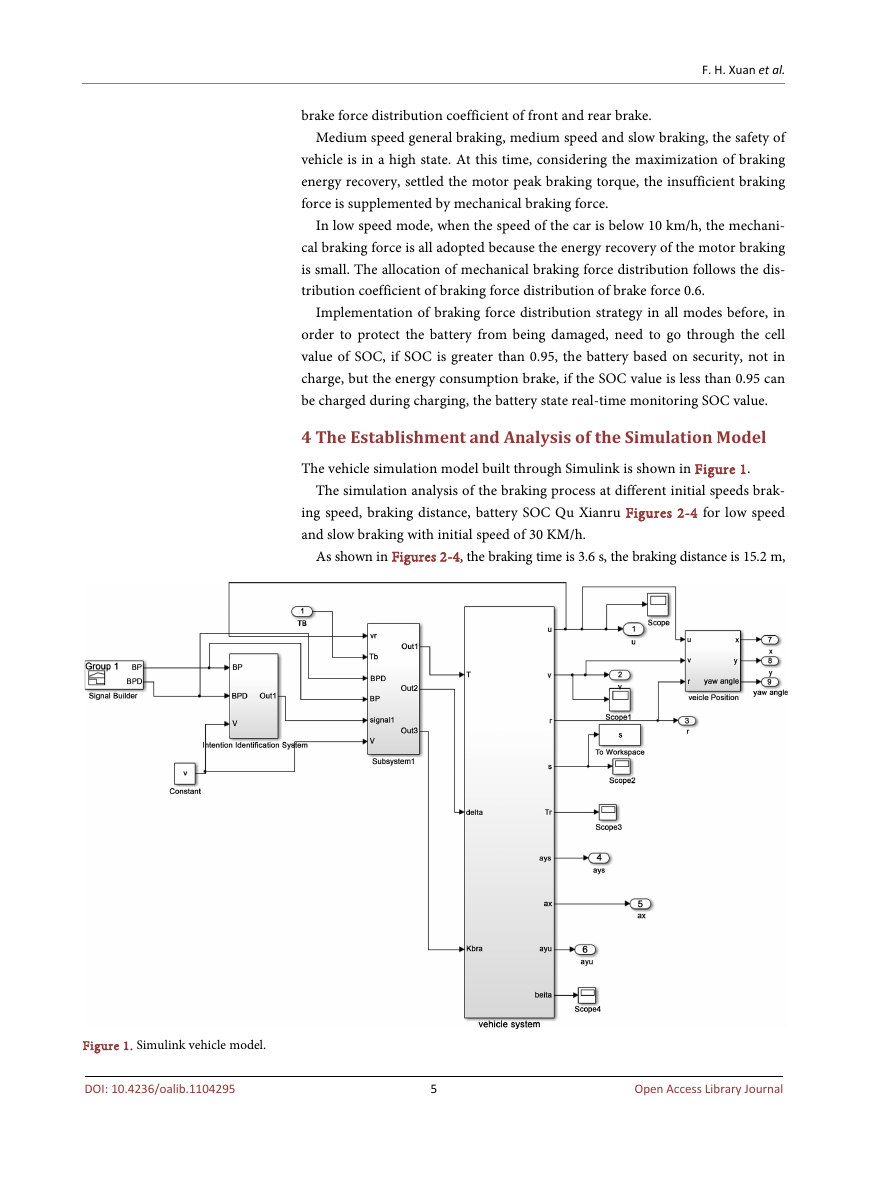
The vehicle simulation model built through Simulink is shown in Figure 1.
The simulation analysis of the braking process at different initial speeds brak-
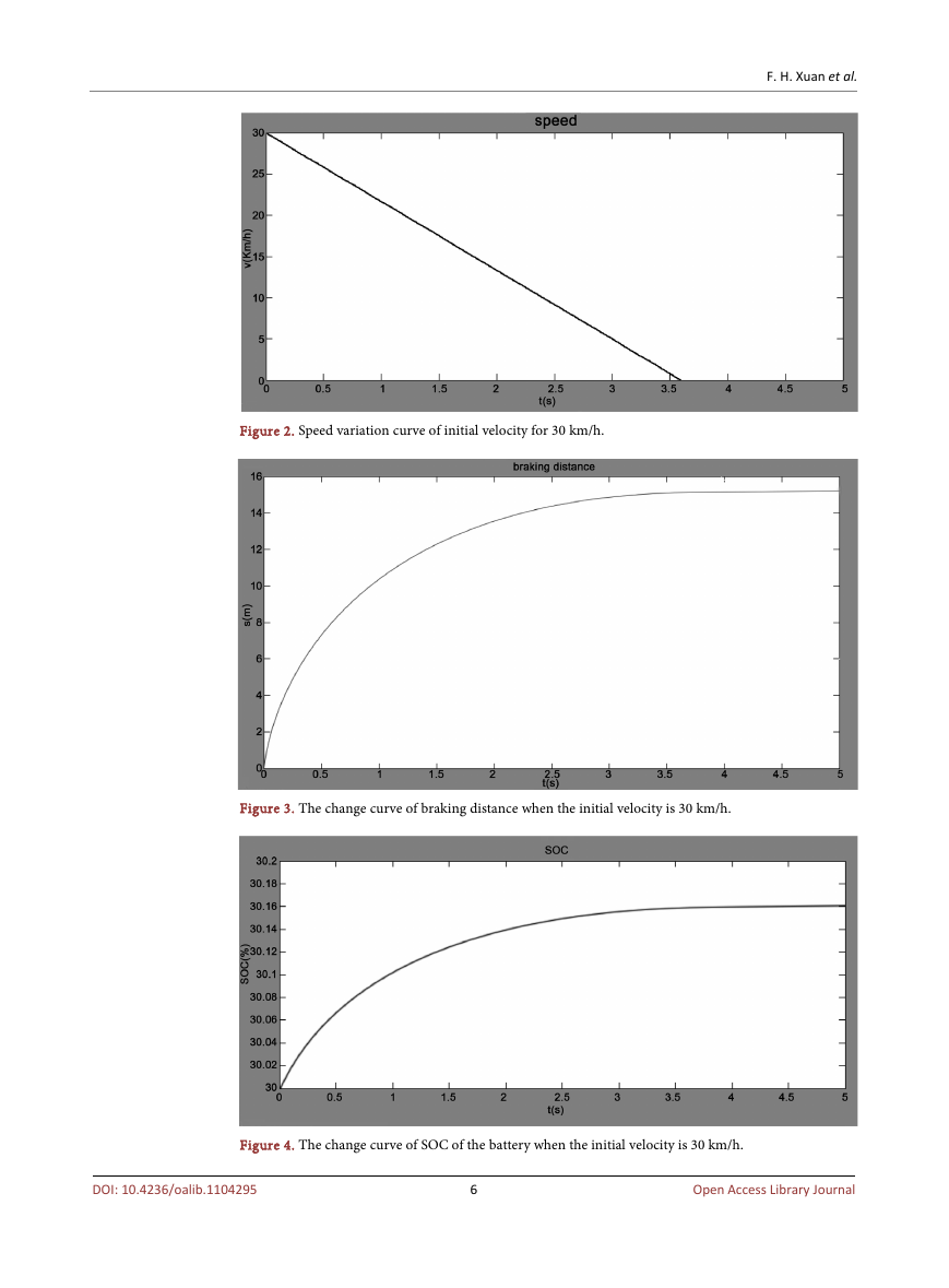
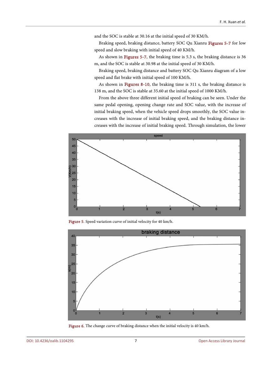
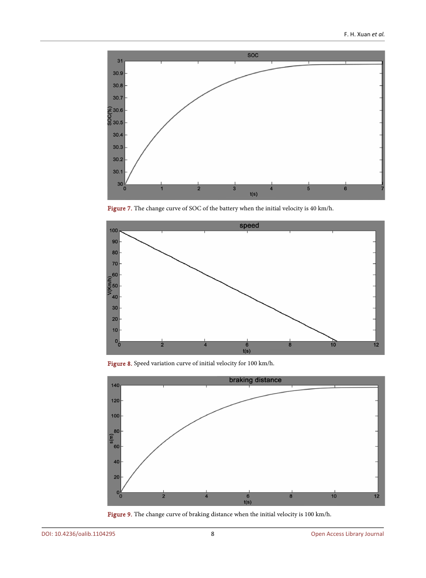
ing speed, braking distance, battery SOC Qu Xianru Figures 2-4 for low speed
and slow braking with initial speed of 30 KM/h.
As shown in Figures 2-4, the braking time is 3.6 s, the braking distance is 15.2 m,
Figure 1. Simulink vehicle model.
DOI: 10.4236/oalib.1104295
5
Open Access Library Journal
�
Figure 2. Speed variation curve of initial velocity for 30 km/h.
Figure 3. The change curve of braking distance when the initial velocity is 30 km/h.
F. H. Xuan et al.
Figure 4. The change curve of SOC of the battery when the initial velocity is 30 km/h.
DOI: 10.4236/oalib.1104295
6
Open Access Library Journal
�
F. H. Xuan et al.
and the SOC is stable at 30.16 at the initial speed of 30 KM/h.
Braking speed, braking distance, battery SOC Qu Xianru Figures 5-7 for low
speed and slow braking with initial speed of 40 KM/h.
As shown in Figures 5-7, the braking time is 5.3 s, the braking distance is 36
m, and the SOC is stable at 30.98 at the initial speed of 30 KM/h.
Braking speed, braking distance and battery SOC Qu Xianru diagram of a low
speed and flat brake with initial speed of 100 KM/h.
As shown in Figures 8-10, the braking time is 311 s, the braking distance is
138 m, and the SOC is stable at 35.60 at the initial speed of 1000 KM/h.
From the above three different initial speed of braking can be seen. Under the
same pedal opening, opening change rate and SOC value, with the increase of
initial braking speed, when the vehicle speed drops smoothly, the SOC value in-
creases with the increase of initial braking speed, and the braking distance in-
creases with the increase of initial braking speed. Through simulation, the lower
Figure 5. Speed variation curve of initial velocity for 40 km/h.
Figure 6. The change curve of braking distance when the initial velocity is 40 km/h.
DOI: 10.4236/oalib.1104295
7
Open Access Library Journal
�
Figure 7. The change curve of SOC of the battery when the initial velocity is 40 km/h.
Figure 8. Speed variation curve of initial velocity for 100 km/h.
F. H. Xuan et al.
Figure 9. The change curve of braking distance when the initial velocity is 100 km/h.
DOI: 10.4236/oalib.1104295
8
Open Access Library Journal
�


 2023年江西萍乡中考道德与法治真题及答案.doc
 2012年重庆南川中考生物真题及答案.doc
 2013年江西师范大学地理学综合及文艺理论基础考研真题.doc
 2020年四川甘孜小升初语文真题及答案I卷.doc
 2020年注册岩土工程师专业基础考试真题及答案.doc
 2023-2024学年福建省厦门市九年级上学期数学月考试题及答案.doc
 2021-2022学年辽宁省沈阳市大东区九年级上学期语文期末试题及答案.doc
 2022-2023学年北京东城区初三第一学期物理期末试卷及答案.doc
 2018上半年江西教师资格初中地理学科知识与教学能力真题及答案.doc
 2012年河北国家公务员申论考试真题及答案-省级.doc
 2020-2021学年江苏省扬州市江都区邵樊片九年级上学期数学第一次质量检测试题及答案.doc
 2022下半年黑龙江教师资格证中学综合素质真题及答案.doc