logo资料库

phy芯片AR8035芯片手册.pdf

第1页 / 共66页
第2页 / 共66页
第3页 / 共66页
第4页 / 共66页
第5页 / 共66页
第6页 / 共66页
第7页 / 共66页
第8页 / 共66页
资料共66页,剩余部分请下载后查看
General Description
Features
AR8035 Functional Block Diagram
Revision History
Table of Contents
1. Pin Descriptions
2. Functional Description
2.1 Transmit Functions
2.2 Receive Functions
2.2.1 Decoder Modes
2.2.2 Analog to Digital Converter
2.2.3 Echo Canceller
2.2.4 NEXT Canceller
2.2.5 Baseline Wander Canceller
2.2.6 Digital Adaptive Equalizer
2.2.7 Auto-Negotiation
2.2.8 Smartspeed Function
2.2.9 Automatic MDI/MDIX Crossover
2.2.10 Polarity Correction
2.3 Loopback Modes
2.3.1 Digital Loopback
2.3.2 External Cable Loopback
2.3.3 Remote PHY Loopback
2.4 Cable Diagnostic Test
2.5 LED Interface
2.6 Power Supplies
2.7 Management Interface
2.8 Atheros Green Ethos®
2.8.1 Low Power Modes
2.8.2 Shorter Cable Power Mode
2.8.3 Hibernation Mode
2.9 IEEE 802.3az and Energy Efficient Ethernet
2.9.1 IEEE 802.3az LPI Mode
2.10 Atheros SmartEEE
2.11 Wake On LAN (WoL)
3. Electrical Characteristics
3.1 Absolute Maximum Ratings
3.2 Recommended Operating Conditions
3.3 RGMII Characteristics
3.4 MDIO Characteristics
3.5 XTAL/OSC Characteristics
3.6 Power Pin Consumption
3.7 Typical Power Consumption Parameters
3.8 Power-on Sequence, Reset and Clock
3.8.1 Power-on Sequence
3.8.2 Reset and Clock Timing
4. Register Descriptions
4.1 Register Summary
4.1.1 Control
4.1.2 Status
4.1.3 PHY Identifier [18:3]
4.1.4 PHY Identifier [19:24]
4.1.5 Auto-Negotiation Advertisement
4.1.6 Link Partner Ability (Base Page)
4.1.7 Auto-Negotiation Expansion
4.1.8 Next Page Transmit
4.1.9 Link Partner Next Page
4.1.10 1000 BASE-T Control
4.1.11 1000 BASE-T Status
4.1.12 MMD Access Address Register
4.1.13 MMD Access Control Register
4.1.14 Extended Status
4.1.15 Function Control
4.1.16 PHY-Specific Status
4.1.17 Interrupt Enable
4.1.18 Interrupt Status
4.1.19 Smart Speed
4.1.20 Cable Diagnostic Tester Control
4.1.21 LED Control
4.1.22 Cable Defect Tester Status
4.1.23 Debug Port Address Offset
4.1.24 Debug Port Data
4.2 Debug Register Descriptions
4.2.1 RGMII RX Clock Delay Control
4.2.2 RGMII TX Clock Delay Control
4.2.3 Hibernation Control and RGMII GTX Clock Delay Register
4.2.4 100BASE-TX Test Mode Select
4.2.5 1000BT external loopback configure
4.2.6 Rgmii_mode; Test configuration for 10BT
4.2.7 MMD3 (MDIO Manageable Device Address 3 for PCS)
4.2.8 MMD7 (MDIO Manageable Device Address 7 for Auto-Negotiation)
4.3 MDIO Interface Register
4.3.1 PCS Control 1
4.3.2 PCS Status 1
4.3.3 EEE Capability
4.3.4 EEE Wake Error Counter
4.3.5 Wake-on-Lan loc_mac_addr_o
4.3.6 Wake-on-Lan loc_mac_addr_o
4.3.7 Wake-on-Lan loc_mac_addr_o
4.3.8 Rem_phy_lpkb
4.3.9 Smart_eee control1
4.3.10 Smart_eee control2
4.3.11 Smart_eee control3
4.3.12 AN status
4.3.13 AN XNP transmit1
4.3.14 AN XNP transmit2
4.3.15 EEE advertisement
4.3.16 EEE LP advertisement
5. Package Dimensions
6. Ordering Information
7. Top-side Marking
Data Sheet March 2012 Ver. 2.1 function as the complete 802.3az system. The key features supported by the device are: n 10BASE-Te PHY supports reduced transmit n 100BASE-TX and 1000BASE-T use Low Power Idle (LPI) mode to turn off unused analog and digital blocks to save power while data traffic is in idle. Features n 10BASE-Te/100BASE-TX/1000 BASE-T amplitude. IEEE 802.3 compliant AR8035 Integrated 10/100/1000 Mbps Ethernet Transceiver General Description The AR8035 is part of the Arctic family of devices - which includes the AR8031, AR8033, and the AR8035. It is Atheros’ 4th generation, single port 10/100/1000 Mbps Tri-speed Ethernet PHY. It supports RGMII interface to the MAC.™ The AR8035 provides a low power, low BOM (Bill of Materials) cost solution for comprehensive applications including consumer, enterprise, carrier and home networks such as PC, HDTV, Gaming machines, Blue-ray players, IPTV STB, Media Players, IP Cameras, NAS, Printers, Digital Photo Frames, MoCA/Homeplug (Powerline)/EoC/ adapters and Home Router & Gateways, etc. The AR8035 integrates Atheros latest Green Ethos® power saving technologies and significantly saves power not only during work time, but also during overtime. Atheros Green Ethos® power savings include ultra-low power in cable unplugged mode or port power down mode, and automatic optimized power saving based on cable length. Furthermore, the AR8035 supports Wake-on-LAN (WoL) feature to be able to help manage and regulate total system power requirements. The AR8035 embeds CDT (Cable Diagnostics Test) technology on-chip which allows customers to measure cable length, detect the cable status, and identify remote and local PHY malfunctions, bad or marginal patch cord segments or connectors. Some of the possible problems that can be detected include opens, shorts, cable impedance mismatch, bad connectors, termination mismatch, and a bad transformer. The AR8035 also integrates a voltage regulator on chip. It reduces the termination R/C circuitry on both the MAC interface (RGMII) and line side. The AR8035 supports IEEE 802.3az Energy Efficient Ethernet (EEE) standard and Atheros proprietary SmartEEE, which allows legacy MAC/SoC devices without 802.3az support to tolerance of ± 6kV CAT5 cable duplex) n Supports 1000 BASE-T PCS and auto- negotiation with next page support n Supports RGMII interface to MAC devices with a broad I/O voltage level options including 2.5V, 1.8V and 1.5V, and is compatible with 3.3V I/O n RGMII timing modes support internal delay and external delay on Rx path n Error-free operation up to 140 meters of n Supports Atheros latest Green Ethos® power saving modes with internal automatic DSP power saving scheme n Supports 802.3az (Energy Efficient Ethernet) n Fully integrated digital adaptive equalizers, echo cancellers, and near end crosstalk (NEXT) cancellers n Supports Wake-on-LAN (WoL) to detect magic packet and notify the sleeping system to wake up n A robust Cable Discharge Event (CDE) n A robust surge protection with ±750V/ differential mode and ±4KV/common mode n Jumbo Frame support up to 10KB (full n All digital baseline wander correction n Automatic channel swap (ACS) n Automatic MDI/MDIX crossover n Automatic polarity correction n IEEE 802.3u compliant Auto-Negotiation n Software programmable LED modes n Multiple Loopback modes for diagnostics © 2011–2012 by Atheros Communications, Inc. All rights reserved. Atheros®, Atheros Driven®, Align®, Atheros XR®, Driving the Wireless Future®, Intellon®, No New Wires®, Orion® , PLC4Trucks®, Powerpacket®, Spread Spectrum Carrier®, SSC®, ROCm®, Super A/G®, Super G®, Super N®, The Air is Cleaner at 5-GHz®, Total 802.11®, U-Nav®, Wake on Wireless®, Wireless Future. Unleashed Now.®, and XSPAN®, are registered by Atheros Communications, Inc. Atheros SST™, Signal-Sustain Technology™, Ethos™, Install N Go™, IQUE™, ROCm™, amp™, Simpli-Fi™, There is Here™, U-Map™, U-Tag™, and 5-UP™ are trademarks of Atheros Communications, Inc. The Atheros logo is a registered trademark of Atheros Communications, Inc. All other trademarks are the property of their respective holders. Subject to change without • 1 COMPANY CONFIDENTIAL
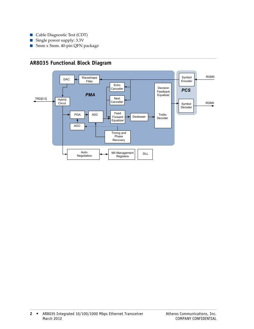
n Cable Diagnostic Test (CDT) n Single power supply: 3.3V n 5mm x 5mm. 40-pin QFN package AR8035 Functional Block Diagram DAC Waveshape Filter TRD[0:3] Hybrid Circut PMA PGA ADC AGC Echo Canceller Next Canceller Feed Forward Equalizer Timing and Phase Recovery Symbol Encoder PCS Symbol Decoder RGMII RGMII Decision Feedback Equalizer Trellis Decoder Deskewer Auto- Negotiation MII Management Registers DLL 2 AR8035 Integrated 10/100/1000 Mbps Ethernet Transceiver 2 March 2012 Atheros Communications, Inc. COMPANY CONFIDENTIAL
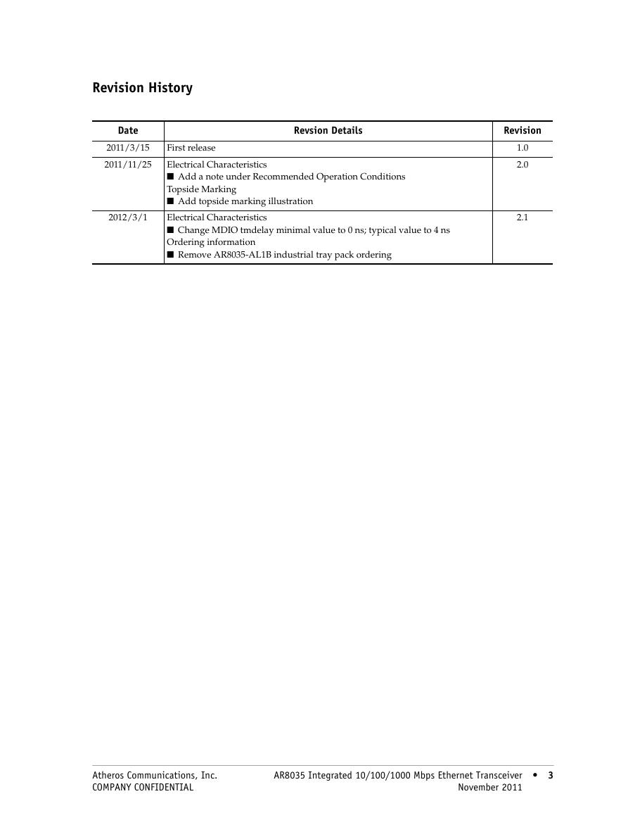
Revision History Date 2011/3/15 2011/11/25 2012/3/1 Revsion Details Revision First release Electrical Characteristics n Add a note under Recommended Operation Conditions Topside Marking n Add topside marking illustration Electrical Characteristics n Change MDIO tmdelay minimal value to 0 ns; typical value to 4 ns Ordering information n Remove AR8035-AL1B industrial tray pack ordering 1.0 2.0 2.1 Atheros Communications, Inc. COMPANY CONFIDENTIAL AR8035 Integrated 10/100/1000 Mbps Ethernet Transceiver 3 November 2011 3
4 AR8035 Integrated 10/100/1000 Mbps Ethernet Transceiver 4 November 2011 Atheros Communications, Inc. COMPANY CONFIDENTIAL
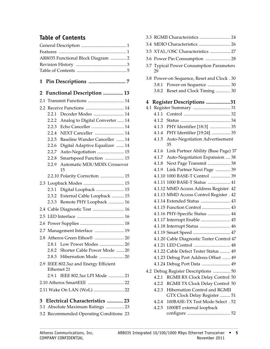
Table of Contents General Description ........................................ 1 Features ............................................................ 1 AR8035 Functional Block Diagram .............. 2 Revision History ............................................. 3 Table of Contents ............................................ 5 1 Pin Descriptions ............................ 7 2 Functional Description ............... 13 2.1 Transmit Functions ................................ 14 2.2 Receive Functions .................................. 14 2.2.1 Decoder Modes ........................... 14 2.2.2 Analog to Digital Converter ...... 14 2.2.3 Echo Canceller ............................. 14 2.2.4 NEXT Canceller .......................... 14 2.2.5 Baseline Wander Canceller ....... 14 2.2.6 Digital Adaptive Equalizer ....... 14 2.2.7 Auto-Negotiation ........................ 15 2.2.8 Smartspeed Function ................. 15 2.2.9 Automatic MDI/MDIX Crossover 15 2.2.10 Polarity Correction ..................... 15 2.3 Loopback Modes .................................... 15 2.3.1 Digital Loopback ......................... 15 2.3.2 External Cable Loopback ........... 15 2.3.3 Remote PHY Loopback .............. 16 2.4 Cable Diagnostic Test ............................ 16 2.5 LED Interface .......................................... 16 2.6 Power Supplies ....................................... 18 2.7 Management Interface .......................... 19 2.8 Atheros Green Ethos® .......................... 20 2.8.1 Low Power Modes ...................... 20 2.8.2 Shorter Cable Power Mode ....... 20 2.8.3 Hibernation Mode ...................... 20 2.9 IEEE 802.3az and Energy Efficient Ethernet 21 2.9.1 IEEE 802.3az LPI Mode .............. 21 2.10 Atheros SmartEEE ................................ 22 2.11 Wake On LAN (WoL) ........................... 22 3 Electrical Characteristics ............ 23 3.1 Absolute Maximum Ratings ................ 23 3.2 Recommended Operating Conditions 23 3.3 RGMII Characteristics ........................... 24 3.4 MDIO Characteristics ............................ 26 3.5 XTAL/OSC Characteristics .................. 27 3.6 Power Pin Consumption ...................... 28 3.7 Typical Power Consumption Parameters 29 3.8 Power-on Sequence, Reset and Clock . 30 3.8.1 Power-on Sequence .................... 30 3.8.2 Reset and Clock Timing ............. 30 4 Register Descriptions ..................31 4.1 Register Summary ................................. 31 4.1.1 Control ......................................... 32 4.1.2 Status ............................................ 34 4.1.3 PHY Identifier [18:3] .................. 35 4.1.4 PHY Identifier [19:24] ................ 35 4.1.5 Auto-Negotiation Advertisement 35 4.1.6 Link Partner Ability (Base Page) 37 4.1.7 Auto-Negotiation Expansion .... 38 4.1.8 Next Page Transmit .................... 38 4.1.9 Link Partner Next Page ............. 39 4.1.10 1000 BASE-T Control ................. 39 4.1.11 1000 BASE-T Status .................... 41 4.1.12 MMD Access Address Register 42 4.1.13 MMD Access Control Register . 42 4.1.14 Extended Status .......................... 43 4.1.15 Function Control ......................... 43 4.1.16 PHY-Specific Status .................... 44 4.1.17 Interrupt Enable .......................... 45 4.1.18 Interrupt Status ........................... 46 4.1.19 Smart Speed ................................. 47 4.1.20 Cable Diagnostic Tester Control 47 4.1.21 LED Control ................................ 48 4.1.22 Cable Defect Tester Status ......... 49 4.1.23 Debug Port Address Offset ....... 49 4.1.24 Debug Port Data ......................... 49 4.2 Debug Register Descriptions ............... 50 4.2.1 RGMII RX Clock Delay Control 50 4.2.2 RGMII TX Clock Delay Control 50 4.2.3 Hibernation Control and RGMII GTX Clock Delay Register ......... 51 4.2.4 100BASE-TX Test Mode Select . 52 4.2.5 1000BT external loopback configure ...................................... 52 Atheros Communications, Inc. COMPANY CONFIDENTIAL AR8035 Integrated 10/100/1000 Mbps Ethernet Transceiver 5 November 2011 5
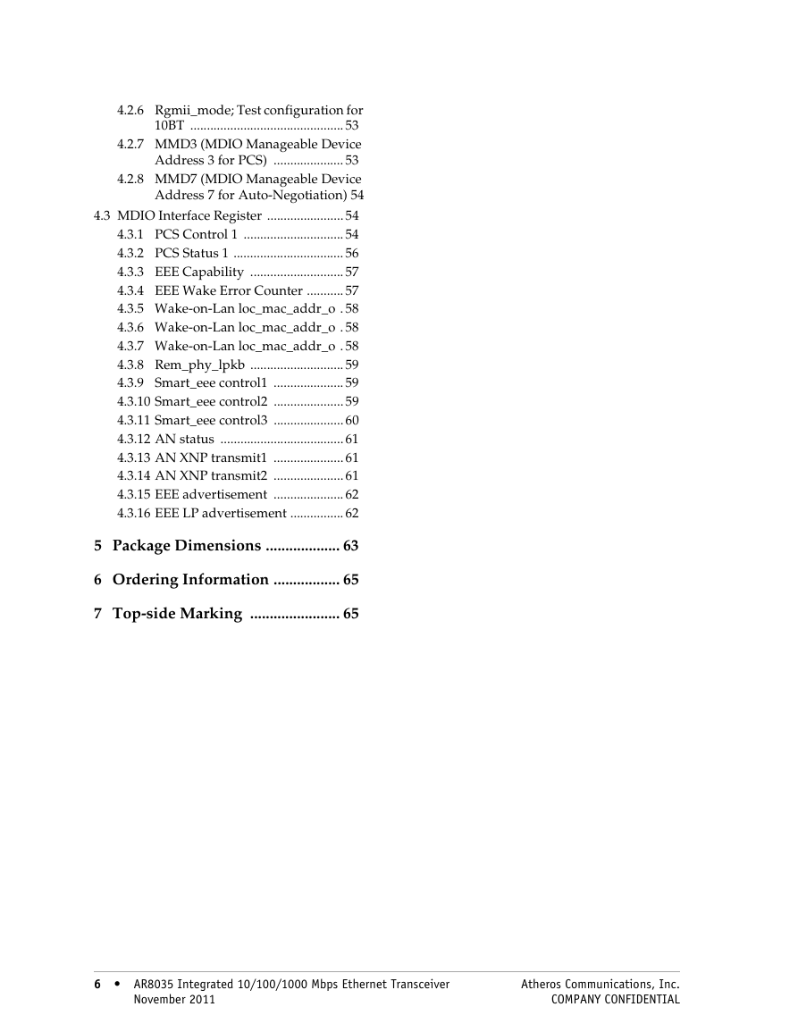
4.2.6 Rgmii_mode; Test configuration for 10BT .............................................. 53 4.2.7 MMD3 (MDIO Manageable Device Address 3 for PCS) ..................... 53 4.2.8 MMD7 (MDIO Manageable Device Address 7 for Auto-Negotiation) 54 4.3 MDIO Interface Register ....................... 54 4.3.1 PCS Control 1 .............................. 54 4.3.2 PCS Status 1 ................................. 56 4.3.3 EEE Capability ............................ 57 4.3.4 EEE Wake Error Counter ........... 57 4.3.5 Wake-on-Lan loc_mac_addr_o . 58 4.3.6 Wake-on-Lan loc_mac_addr_o . 58 4.3.7 Wake-on-Lan loc_mac_addr_o . 58 4.3.8 Rem_phy_lpkb ............................ 59 4.3.9 Smart_eee control1 ..................... 59 4.3.10 Smart_eee control2 ..................... 59 4.3.11 Smart_eee control3 ..................... 60 4.3.12 AN status ..................................... 61 4.3.13 AN XNP transmit1 ..................... 61 4.3.14 AN XNP transmit2 ..................... 61 4.3.15 EEE advertisement ..................... 62 4.3.16 EEE LP advertisement ................ 62 5 Package Dimensions ................... 63 6 Ordering Information ................. 65 7 Top-side Marking ....................... 65 6 AR8035 Integrated 10/100/1000 Mbps Ethernet Transceiver 6 November 2011 Atheros Communications, Inc. COMPANY CONFIDENTIAL
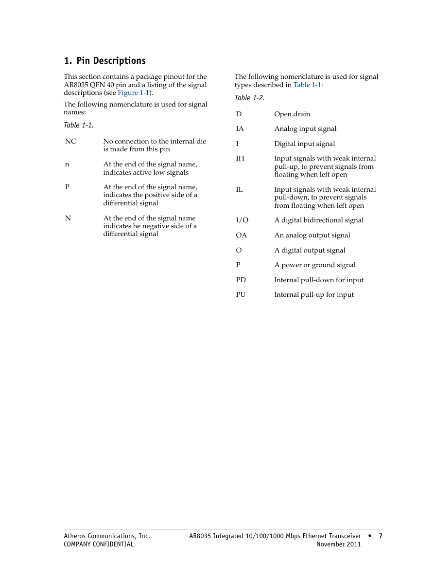
1. Pin Descriptions This section contains a package pinout for the AR8035 QFN 40 pin and a listing of the signal descriptions (see Figure 1-1). The following nomenclature is used for signal names: Table 1-1. NC n P N No connection to the internal die is made from this pin At the end of the signal name, indicates active low signals At the end of the signal name, indicates the positive side of a differential signal At the end of the signal name indicates he negative side of a differential signal The following nomenclature is used for signal types described in Table 1-1: Table 1-2. D IA I IH IL I/O OA O P PD PU Open drain Analog input signal Digital input signal Input signals with weak internal pull-up, to prevent signals from floating when left open Input signals with weak internal pull-down, to prevent signals from floating when left open A digital bidirectional signal An analog output signal A digital output signal A power or ground signal Internal pull-down for input Internal pull-up for input Atheros Communications, Inc. COMPANY CONFIDENTIAL AR8035 Integrated 10/100/1000 Mbps Ethernet Transceiver 7 November 2011 7
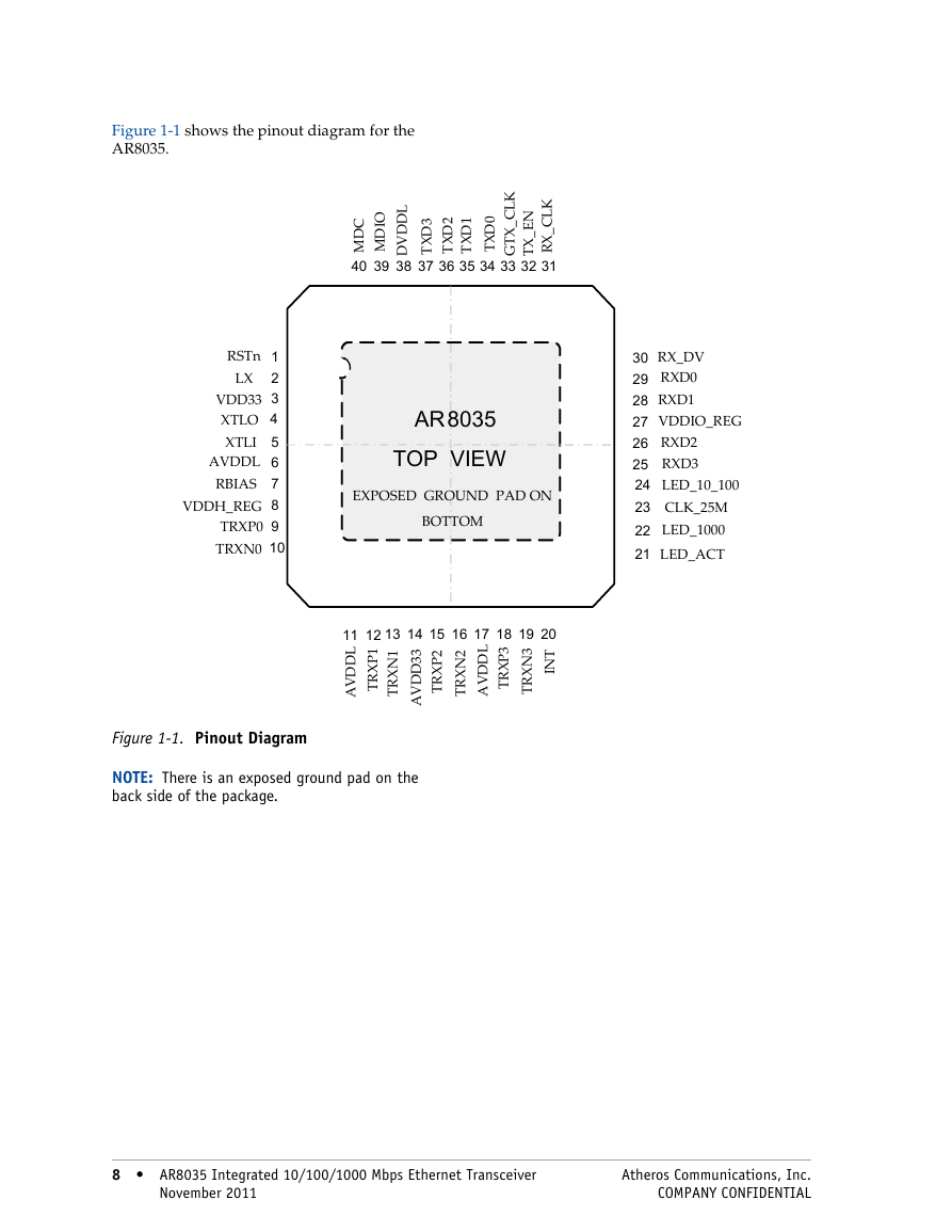
Figure 1-1 shows the pinout diagram for the AR8035. I L D D V D O D M C 3 D D X M T 40 39 38 37 K L C _ X T G 36 35 34 33 1 D X T 0 D X T 2 D X T K L C _ X R 31 N E _ X T 32 RSTn LX VDD33 XTLO XTLI AVDDL RBIAS VDDH_REG TRXP0 TRXN0 1 2 3 4 5 6 7 8 9 10 AR8035 TOP VIEW EXPOSED GROUND PAD ON BOTTOM 11 12 13 14 15 16 17 18 19 20 L D D V A 1 P X R T 1 N X R T 3 3 D D V A 2 P X R T 2 N X R T L D D V A 3 P X R T 3 N X R T T N I 30 29 28 27 26 25 24 23 22 21 RX_DV RXD0 RXD1 VDDIO_REG RXD2 RXD3 LED_10_100 CLK_25M LED_1000 LED_ACT Figure 1-1. Pinout Diagram NOTE: There is an exposed ground pad on the back side of the package. 8 AR8035 Integrated 10/100/1000 Mbps Ethernet Transceiver 8 November 2011 Atheros Communications, Inc. COMPANY CONFIDENTIAL
分享到:
收藏