logo资料库

CameraLink_v2.0 spec 标准协议.pdf

第1页 / 共106页
第2页 / 共106页
第3页 / 共106页
第4页 / 共106页
第5页 / 共106页
第6页 / 共106页
第7页 / 共106页
第8页 / 共106页
资料共106页,剩余部分请下载后查看
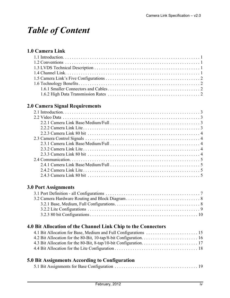
1.0 Camera Link
1.1 Introduction
1.2 Conventions
1.3 LVDS Technical Description
1.4 Channel Link
1.5 Camera Link’s Five Configurations
1.6 Technology Benefits
1.6.1 Smaller Connectors and Cables
1.6.2 High Data Transmission Rates
2.0 Camera Signal Requirements
2.1 Introduction
2.2 Video Data
2.2.1 Camera Link Base/Medium/Full
2.2.2 Camera Link Lite
2.2.3 Camera Link 80 bit
2.3 Camera Control Signals
2.3.1 Camera Link Base/Medium/Full
2.3.2 Camera Link Lite
2.3.3 Camera Link 80 bit
2.4 Communication
2.4.1 Camera Link Base/Medium/Full
2.4.2 Camera Link Lite
2.4.3 Camera Link 80 bit
3.0 Port Assignments
3.1 Port Definition - all Configurations
3.2 Camera Hardware Routing and Block Diagram
3.2.1 Base, Medium, Full Configurations
3.2.2 Lite Configurations
3.2.3 80 bit Configurations
4.0 Bit Allocation of the Channel Link Chip to the Connectors
4.1 Bit Allocation for Base, Medium and Full Configurations
4.2 Bit Allocation for the 80-Bit, 10-tap/8-bit Configuration
4.3 Bit Allocation for the 80-Bit, 8-tap/10-bit Configuration
4.4 Bit Allocation for the Lite Configuration
5.0 Bit Assignments According to Configuration
5.1 Bit Assignments for Base Configuration
5.2 Bit Assignment for Medium Configuration
5.3 Bit Assignment for Full/80 bit Configuration
5.4 Bit Assignments for 80 bit Configuration, 10-tap/8-bit mode
5.5 Bit Assignments for 80 bit Configuration, 8-tap/10-bit mode
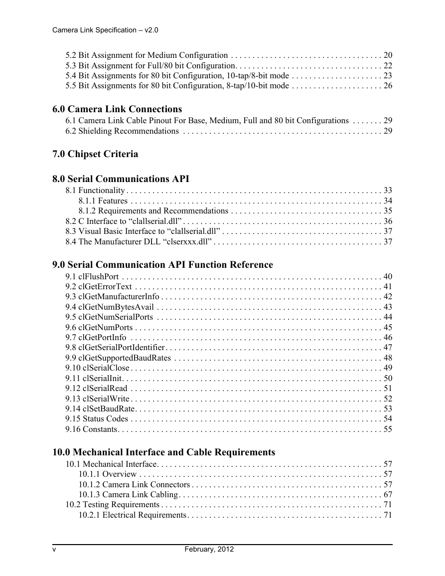
6.0 Camera Link Connections
6.1 Camera Link Cable Pinout For Base, Medium, Full and 80 bit Configurations
6.2 Shielding Recommendations
7.0 Chipset Criteria
8.0 Serial Communications API
8.1 Functionality
8.1.1 Features
8.1.2 Requirements and Recommendations
8.1.2.1 Frame Grabber Companies
8.1.2.2 Camera Companies
8.2 C Interface to “clallserial.dll”
8.3 Visual Basic Interface to “clallserial.dll”
8.4 The Manufacturer DLL “clserxxx.dll”
9.0 Serial Communication API Function Reference
9.1 clFlushPort
9.2 clGetErrorText
9.3 clGetManufacturerInfo
9.4 clGetNumBytesAvail
9.5 clGetNumSerialPorts
9.6 clGetNumPorts
9.7 clGetPortInfo
9.8 clGetSerialPortIdentifier
9.9 clGetSupportedBaudRates
9.10 clSerialClose
9.11 clSerialInit
9.12 clSerialRead
9.13 clSerialWrite
9.14 clSetBaudRate
9.15 Status Codes
9.16 Constants
10.0 Mechanical Interface and Cable Requirements
10.1 Mechanical Interface
10.1.1 Overview
10.1.2 Camera Link Connectors
10.1.2.1 Contact Finish
10.1.2.2 Camera Link (CL) Connector
10.1.2.3 Miniature Camera Link (MiniCL) Connector
10.1.2.4 Power over Camera Link Lite (PoCL-Lite) Connector
10.1.2.5 Connector Pin Assignment for Base, Medium and Full Configuration Camera Link
10.1.2.6 Connector Pin Assignment for PoCL-Lite Configuration
10.1.2.7 Mechanical Drawings
10.1.2.8 Connector Retention
10.1.2.9 Camera Link Connector Jack Socket Requirements
10.1.2.10 Camera Link Cable Threaded Fastener Requirements
10.1.2.11 MiniCL/PoCL-Lite Connector Jack Socket Requirements
10.1.2.12 MiniCL/PoCL-Lite Cable Threaded Fastener Requirements
10.1.3 Camera Link Cabling
10.1.3.1 Camera Link Cable Certification
10.1.3.2 Cable Jacket
10.1.3.3 Shield Requirement
10.1.3.4 Cable Length
10.1.3.5 Types of Camera Link Cabling
10.1.3.6 Cable Requirements – Camera Link
10.1.3.6.1 Number of Signal Conductors
10.1.3.6.2 Insulation
10.1.3.6.3 Wire Gauge
10.1.3.7 Cable Requirements – Power over Camera Link (PoCL)
10.1.3.7.1 Number of Signal Conductors
10.1.3.7.2 Insulation – Differential Pairs
10.1.3.7.3 Insulation – Power and Drain Conductors
10.1.3.7.4 Wire Gauge
10.1.3.7.5 Labeling
10.1.3.8 Cable Requirements - PoCL-Lite Configuration
10.1.3.8.1 Number of Signal Conductors
10.1.3.8.2 Insulation - Differential Pairs
10.1.3.8.3 Insulation - Power and Drain Conductors
10.1.3.8.4 Wire Gauge
10.2 Testing Requirements
10.2.1 Electrical Requirements
10.2.1.1 Dielectric Withstanding Voltage of PoCL and PoCL-Lite power wires
10.2.1.2 Shield Isolation
10.2.1.3 Impedance of Differential Signal Lines
10.2.1.4 Near End Crosstalk of Differential Signal Lines
10.2.1.5 Far End Crosstalk of Differential Signal Lines
10.2.1.6 Crosstalk of Power Lines (PoCL and PoCL-Lite cabling only)
Test Conditions
10.2.1.7 Within Pair Skew of Differential Signal Lines
10.2.1.8 Pair to Pair Skew of Differential Signal Lines within data and clock groups
10.2.1.9 Eye Mask Definition
10.2.1.10 Current Capacity for PoCL and PoCL-Lite
10.2.1.11 Conductor Resistance for PoCL and PoCL-Lite
11.0 Power over Camera Link (PoCL)
11.1 Introduction
11.1.1 Overview
11.1.2 Backward Compatibility
11.1.3 Simplified Block Diagram (Base Configuration)
11.2 PoCL Pinouts for Specific Configurations
11.2.1 Camera Link Cable Pinout Changes For PoCL Configuration
11.2.2 Camera Link Cable Pinout For PoCL-Lite Configurations
11.3 Camera Requirements
11.3.1 Operating Requirements
11.3.1.1 Voltage
11.3.1.2 Power
11.3.2 Support for SafePower
11.3.2.1 Input Resistance
11.3.2.2 Input Capacitance
11.3.2.3 Camera Link Clock
11.3.3 Labeling
11.3.4 Medium, Full, 80 bit Cameras
11.3.5 Additional Power Connectors
11.4 Frame Grabber Requirements
11.4.1 Compatibility
11.4.2 Operating Requirements
11.4.2.1 Voltage
11.4.2.2 Power
11.4.3 Protection Systems
11.4.3.1 Over-Current Protection (OCP)
11.4.3.2 SafePower
11.4.4 Support for Medium/Full/80 bit Cameras
11.4.5 Power Supply Filter (LPF)
11.4.6 Labeling
11.4.7 Indicator Lamps
11.5 Cable Requirements
11.6 Miscellaneous
11.6.1 Repeaters
Specifications of the Camera Link Interface Standard for Digital Cameras and Frame Grabbers Camera Link Specifications version 2.0 Includes: 900 Victors Way, Suite 140 • Ann Arbor, Michigan 48108 USA • www.visiononline.org
Camera Link Specification – v2.0 Camera Link Licensing and Logo Usage Camera Link is a widely adopted standard and is used on hundreds of products on the market today. The standard is a hardware specification that standardizes the connection between cameras and frame grabbers. It defines a complete interface which includes provisions for data transfer, camera timing, serial communications, and real time signaling to the camera. The AIA owns the trademarks and trade names for Camera Link, Power Over Camera Link, and Power Over Camera Link Lite. All commercial products developed using the Camera Link standard must license the standard and qualify for the right to use the name and logo. To qualify, each product must have the proper paperwork submitted to the AIA and must self-certify to be compliant with the Camera Link standard. More information on licensing Camera Link can be found at www.visiononline.org/standards. 3M™ is a trademark of the 3M Company. Channel Link™ is a trademark of National Semiconductor. Flatlink™ is a trademark of Texas Instruments. Panel Link™ is a trademark of Silicon Image. The Camera Link logos may be used only in conjunction with licensed products which have self-certified to be compliant with the Camera Link standard. No part of this publication may be reproduced in any form, in an electronic retrieval system or otherwise, without the prior written permission of the AIA. ©2012 AIA All Rights Reserved i February, 2012
About this Document Camera Link Specification – v2.0 The following specifications provide a framework for Camera Link and Camera Link Lite communication. Version 2.0 incorporates a number of previous annexes (Power over Camera Link, Miniature Camera Link connectors, etc) to provide a comprehensive consolidation into 1 contiguous specification. The specifications are deliberately defined to be open, allowing camera and frame grabber manufacturers to differentiate their products. Additional recommendations may be added at a later date, which will not affect the accuracy of the information in this document. Backward compatibility is assured for all products. Acknowledgements Participating Companies The following companies participated in the development, definition and review of this version and previous versions of the Camera Link standard: 3M Electronic Solutions Division Active Silicon Ltd. ADIMEC Advanced Image Systems BV Alacron, Inc. AVAL DATA CORPORATION Basler Vision Technologies BitFlow, Inc. Carrio Cabling Corporation CIS Corporation Cognex Corporation Components Express, Inc. e2v Semiconductors ELTEC Elktronik AG Engineering Design Team, Inc. EPIX, Inc. Euresys, Inc. Fairfield Imaging, Inc. FAST Corporation W. L. Gore & Associates Hitachi Kokusai Electric America, Ltd. Imperx Incorporated Intercon 1 JAI Leutron Vision, Inc. Matrox Electronic Systems Ltd. Microtechnica Co., Ltd Mikrotron GmbH National Instruments Northwire, Inc. OCP Group, Inc. Photonfocus Ltd. PPT VISION, Inc. PULNiX America, Inc. Redlake MASD, LLC Sentec America SICK|IVP AB Siemens, Inc. Silicon Software Sony Visual Imaging Products STAC Corporation Stemmer Imaging GmbH Teledyne DALSA Thinklogical TKM Technologies, Inc. Toshiba Teli Corporation TVI Vision February, 2012 ii
Camera Link Specification – v2.0 iii February, 2012
Table of Content Camera Link Specification – v2.0 1.0 Camera Link 1.1 Introduction. . . . . . . . . . . . . . . . . . . . . . . . . . . . . . . . . . . . . . . . . . . . . . . . . . . . . . . . . . . . . 1 1.2 Conventions . . . . . . . . . . . . . . . . . . . . . . . . . . . . . . . . . . . . . . . . . . . . . . . . . . . . . . . . . . . . 1 1.3 LVDS Technical Description . . . . . . . . . . . . . . . . . . . . . . . . . . . . . . . . . . . . . . . . . . . . . . . 1 1.4 Channel Link. . . . . . . . . . . . . . . . . . . . . . . . . . . . . . . . . . . . . . . . . . . . . . . . . . . . . . . . . . . . 1 1.5 Camera Link’s Five Configurations . . . . . . . . . . . . . . . . . . . . . . . . . . . . . . . . . . . . . . . . . . 2 1.6 Technology Benefits . . . . . . . . . . . . . . . . . . . . . . . . . . . . . . . . . . . . . . . . . . . . . . . . . . . . . . 2 1.6.1 Smaller Connectors and Cables . . . . . . . . . . . . . . . . . . . . . . . . . . . . . . . . . . . . . . . . . 2 1.6.2 High Data Transmission Rates . . . . . . . . . . . . . . . . . . . . . . . . . . . . . . . . . . . . . . . . . 2 2.0 Camera Signal Requirements 2.1 Introduction. . . . . . . . . . . . . . . . . . . . . . . . . . . . . . . . . . . . . . . . . . . . . . . . . . . . . . . . . . . . . 3 2.2 Video Data . . . . . . . . . . . . . . . . . . . . . . . . . . . . . . . . . . . . . . . . . . . . . . . . . . . . . . . . . . . . . 3 2.2.1 Camera Link Base/Medium/Full . . . . . . . . . . . . . . . . . . . . . . . . . . . . . . . . . . . . . . . . 3 2.2.2 Camera Link Lite . . . . . . . . . . . . . . . . . . . . . . . . . . . . . . . . . . . . . . . . . . . . . . . . . . . . 3 2.2.3 Camera Link 80 bit . . . . . . . . . . . . . . . . . . . . . . . . . . . . . . . . . . . . . . . . . . . . . . . . . . 4 2.3 Camera Control Signals . . . . . . . . . . . . . . . . . . . . . . . . . . . . . . . . . . . . . . . . . . . . . . . . . . . 4 2.3.1 Camera Link Base/Medium/Full . . . . . . . . . . . . . . . . . . . . . . . . . . . . . . . . . . . . . . . . 4 2.3.2 Camera Link Lite . . . . . . . . . . . . . . . . . . . . . . . . . . . . . . . . . . . . . . . . . . . . . . . . . . . . 4 2.3.3 Camera Link 80 bit . . . . . . . . . . . . . . . . . . . . . . . . . . . . . . . . . . . . . . . . . . . . . . . . . . 4 2.4 Communication. . . . . . . . . . . . . . . . . . . . . . . . . . . . . . . . . . . . . . . . . . . . . . . . . . . . . . . . . . 5 2.4.1 Camera Link Base/Medium/Full . . . . . . . . . . . . . . . . . . . . . . . . . . . . . . . . . . . . . . . . 5 2.4.2 Camera Link Lite . . . . . . . . . . . . . . . . . . . . . . . . . . . . . . . . . . . . . . . . . . . . . . . . . . . . 5 2.4.3 Camera Link 80 bit . . . . . . . . . . . . . . . . . . . . . . . . . . . . . . . . . . . . . . . . . . . . . . . . . . 5 3.0 Port Assignments 3.1 Port Definition - all Configurations . . . . . . . . . . . . . . . . . . . . . . . . . . . . . . . . . . . . . . . . . . 7 3.2 Camera Hardware Routing and Block Diagram . . . . . . . . . . . . . . . . . . . . . . . . . . . . . . . . . 8 3.2.1 Base, Medium, Full Configurations. . . . . . . . . . . . . . . . . . . . . . . . . . . . . . . . . . . . . . 8 3.2.2 Lite Configurations . . . . . . . . . . . . . . . . . . . . . . . . . . . . . . . . . . . . . . . . . . . . . . . . . . 9 3.2.3 80 bit Configurations . . . . . . . . . . . . . . . . . . . . . . . . . . . . . . . . . . . . . . . . . . . . . . . . 10 4.0 Bit Allocation of the Channel Link Chip to the Connectors 4.1 Bit Allocation for Base, Medium and Full Configurations . . . . . . . . . . . . . . . . . . . . . . . 15 4.2 Bit Allocation for the 80-Bit, 10-tap/8-bit Configuration. . . . . . . . . . . . . . . . . . . . . . . . . 16 4.3 Bit Allocation for the 80-Bit, 8-tap/10-bit Configuration. . . . . . . . . . . . . . . . . . . . . . . . . 17 4.4 Bit Allocation for the Lite Configuration . . . . . . . . . . . . . . . . . . . . . . . . . . . . . . . . . . . . . 18 5.0 Bit Assignments According to Configuration 5.1 Bit Assignments for Base Configuration . . . . . . . . . . . . . . . . . . . . . . . . . . . . . . . . . . . . . 19 February, 2012 iv
Camera Link Specification – v2.0 5.2 Bit Assignment for Medium Configuration . . . . . . . . . . . . . . . . . . . . . . . . . . . . . . . . . . . 20 5.3 Bit Assignment for Full/80 bit Configuration. . . . . . . . . . . . . . . . . . . . . . . . . . . . . . . . . . 22 5.4 Bit Assignments for 80 bit Configuration, 10-tap/8-bit mode . . . . . . . . . . . . . . . . . . . . . 23 5.5 Bit Assignments for 80 bit Configuration, 8-tap/10-bit mode . . . . . . . . . . . . . . . . . . . . . 26 6.0 Camera Link Connections 6.1 Camera Link Cable Pinout For Base, Medium, Full and 80 bit Configurations . . . . . . . 29 6.2 Shielding Recommendations . . . . . . . . . . . . . . . . . . . . . . . . . . . . . . . . . . . . . . . . . . . . . . 29 7.0 Chipset Criteria 8.0 Serial Communications API 8.1 Functionality . . . . . . . . . . . . . . . . . . . . . . . . . . . . . . . . . . . . . . . . . . . . . . . . . . . . . . . . . . . 33 8.1.1 Features . . . . . . . . . . . . . . . . . . . . . . . . . . . . . . . . . . . . . . . . . . . . . . . . . . . . . . . . . . 34 8.1.2 Requirements and Recommendations . . . . . . . . . . . . . . . . . . . . . . . . . . . . . . . . . . . 35 8.2 C Interface to “clallserial.dll” . . . . . . . . . . . . . . . . . . . . . . . . . . . . . . . . . . . . . . . . . . . . . . 36 8.3 Visual Basic Interface to “clallserial.dll” . . . . . . . . . . . . . . . . . . . . . . . . . . . . . . . . . . . . . 37 8.4 The Manufacturer DLL “clserxxx.dll” . . . . . . . . . . . . . . . . . . . . . . . . . . . . . . . . . . . . . . . 37 9.0 Serial Communication API Function Reference 9.1 clFlushPort . . . . . . . . . . . . . . . . . . . . . . . . . . . . . . . . . . . . . . . . . . . . . . . . . . . . . . . . . . . . 40 9.2 clGetErrorText . . . . . . . . . . . . . . . . . . . . . . . . . . . . . . . . . . . . . . . . . . . . . . . . . . . . . . . . . 41 9.3 clGetManufacturerInfo . . . . . . . . . . . . . . . . . . . . . . . . . . . . . . . . . . . . . . . . . . . . . . . . . . . 42 9.4 clGetNumBytesAvail . . . . . . . . . . . . . . . . . . . . . . . . . . . . . . . . . . . . . . . . . . . . . . . . . . . . 43 9.5 clGetNumSerialPorts . . . . . . . . . . . . . . . . . . . . . . . . . . . . . . . . . . . . . . . . . . . . . . . . . . . . 44 9.6 clGetNumPorts . . . . . . . . . . . . . . . . . . . . . . . . . . . . . . . . . . . . . . . . . . . . . . . . . . . . . . . . . 45 9.7 clGetPortInfo . . . . . . . . . . . . . . . . . . . . . . . . . . . . . . . . . . . . . . . . . . . . . . . . . . . . . . . . . . 46 9.8 clGetSerialPortIdentifier. . . . . . . . . . . . . . . . . . . . . . . . . . . . . . . . . . . . . . . . . . . . . . . . . . 47 9.9 clGetSupportedBaudRates . . . . . . . . . . . . . . . . . . . . . . . . . . . . . . . . . . . . . . . . . . . . . . . . 48 9.10 clSerialClose . . . . . . . . . . . . . . . . . . . . . . . . . . . . . . . . . . . . . . . . . . . . . . . . . . . . . . . . . . 49 9.11 clSerialInit. . . . . . . . . . . . . . . . . . . . . . . . . . . . . . . . . . . . . . . . . . . . . . . . . . . . . . . . . . . . 50 9.12 clSerialRead . . . . . . . . . . . . . . . . . . . . . . . . . . . . . . . . . . . . . . . . . . . . . . . . . . . . . . . . . . 51 9.13 clSerialWrite . . . . . . . . . . . . . . . . . . . . . . . . . . . . . . . . . . . . . . . . . . . . . . . . . . . . . . . . . . 52 9.14 clSetBaudRate. . . . . . . . . . . . . . . . . . . . . . . . . . . . . . . . . . . . . . . . . . . . . . . . . . . . . . . . . 53 9.15 Status Codes . . . . . . . . . . . . . . . . . . . . . . . . . . . . . . . . . . . . . . . . . . . . . . . . . . . . . . . . . . 54 9.16 Constants. . . . . . . . . . . . . . . . . . . . . . . . . . . . . . . . . . . . . . . . . . . . . . . . . . . . . . . . . . . . . 55 10.0 Mechanical Interface and Cable Requirements 10.1 Mechanical Interface. . . . . . . . . . . . . . . . . . . . . . . . . . . . . . . . . . . . . . . . . . . . . . . . . . . . 57 10.1.1 Overview . . . . . . . . . . . . . . . . . . . . . . . . . . . . . . . . . . . . . . . . . . . . . . . . . . . . . . . . 57 10.1.2 Camera Link Connectors . . . . . . . . . . . . . . . . . . . . . . . . . . . . . . . . . . . . . . . . . . . . 57 10.1.3 Camera Link Cabling. . . . . . . . . . . . . . . . . . . . . . . . . . . . . . . . . . . . . . . . . . . . . . . 67 10.2 Testing Requirements . . . . . . . . . . . . . . . . . . . . . . . . . . . . . . . . . . . . . . . . . . . . . . . . . . . 71 10.2.1 Electrical Requirements. . . . . . . . . . . . . . . . . . . . . . . . . . . . . . . . . . . . . . . . . . . . . 71 v February, 2012
Camera Link Specification – v2.0 11.0 Power over Camera Link (PoCL) 11.1 Introduction. . . . . . . . . . . . . . . . . . . . . . . . . . . . . . . . . . . . . . . . . . . . . . . . . . . . . . . . . . . 79 11.1.1 Overview . . . . . . . . . . . . . . . . . . . . . . . . . . . . . . . . . . . . . . . . . . . . . . . . . . . . . . . . 79 11.1.2 Backward Compatibility . . . . . . . . . . . . . . . . . . . . . . . . . . . . . . . . . . . . . . . . . . . . 79 11.1.3 Simplified Block Diagram (Base Configuration) . . . . . . . . . . . . . . . . . . . . . . . . . 80 11.2 PoCL Pinouts for Specific Configurations . . . . . . . . . . . . . . . . . . . . . . . . . . . . . . . . . . . 81 11.2.1 Camera Link Cable Pinout Changes For PoCL Configuration . . . . . . . . . . . . . . . 81 11.2.2 Camera Link Cable Pinout For PoCL-Lite Configurations. . . . . . . . . . . . . . . . . . 81 11.3 Camera Requirements. . . . . . . . . . . . . . . . . . . . . . . . . . . . . . . . . . . . . . . . . . . . . . . . . . . 84 11.3.1 Operating Requirements . . . . . . . . . . . . . . . . . . . . . . . . . . . . . . . . . . . . . . . . . . . . 84 11.3.2 Support for SafePower. . . . . . . . . . . . . . . . . . . . . . . . . . . . . . . . . . . . . . . . . . . . . . 84 11.3.3 Labeling . . . . . . . . . . . . . . . . . . . . . . . . . . . . . . . . . . . . . . . . . . . . . . . . . . . . . . . . . 85 11.3.4 Medium, Full, 80 bit Cameras . . . . . . . . . . . . . . . . . . . . . . . . . . . . . . . . . . . . . . . . 85 11.3.5 Additional Power Connectors . . . . . . . . . . . . . . . . . . . . . . . . . . . . . . . . . . . . . . . . 86 11.4 Frame Grabber Requirements. . . . . . . . . . . . . . . . . . . . . . . . . . . . . . . . . . . . . . . . . . . . . 86 11.4.1 Compatibility . . . . . . . . . . . . . . . . . . . . . . . . . . . . . . . . . . . . . . . . . . . . . . . . . . . . . 86 11.4.2 Operating Requirements . . . . . . . . . . . . . . . . . . . . . . . . . . . . . . . . . . . . . . . . . . . . 87 11.4.3 Protection Systems. . . . . . . . . . . . . . . . . . . . . . . . . . . . . . . . . . . . . . . . . . . . . . . . . 87 11.4.4 Support for Medium/Full/80 bit Cameras . . . . . . . . . . . . . . . . . . . . . . . . . . . . . . . 90 11.4.5 Power Supply Filter (LPF). . . . . . . . . . . . . . . . . . . . . . . . . . . . . . . . . . . . . . . . . . . 90 11.4.6 Labeling . . . . . . . . . . . . . . . . . . . . . . . . . . . . . . . . . . . . . . . . . . . . . . . . . . . . . . . . . 91 11.4.7 Indicator Lamps . . . . . . . . . . . . . . . . . . . . . . . . . . . . . . . . . . . . . . . . . . . . . . . . . . . 91 11.5 Cable Requirements . . . . . . . . . . . . . . . . . . . . . . . . . . . . . . . . . . . . . . . . . . . . . . . . . . . . 91 11.6 Miscellaneous . . . . . . . . . . . . . . . . . . . . . . . . . . . . . . . . . . . . . . . . . . . . . . . . . . . . . . . . . 91 11.6.1 Repeaters . . . . . . . . . . . . . . . . . . . . . . . . . . . . . . . . . . . . . . . . . . . . . . . . . . . . . . . . 91 February, 2012 vi
Camera Link Specification – v2.0 vii February, 2012
分享到:
收藏