VBA23001-R.3762.A
作成承認印 配布許可印
サービス
計画課
M
VBA23001
REPAIR MANUAL
Printed in Japan SEP 2008
Copyright c 2008 by Nikon Corporation.
All Rights Reserved.
無断転載を禁ず !!
INC�
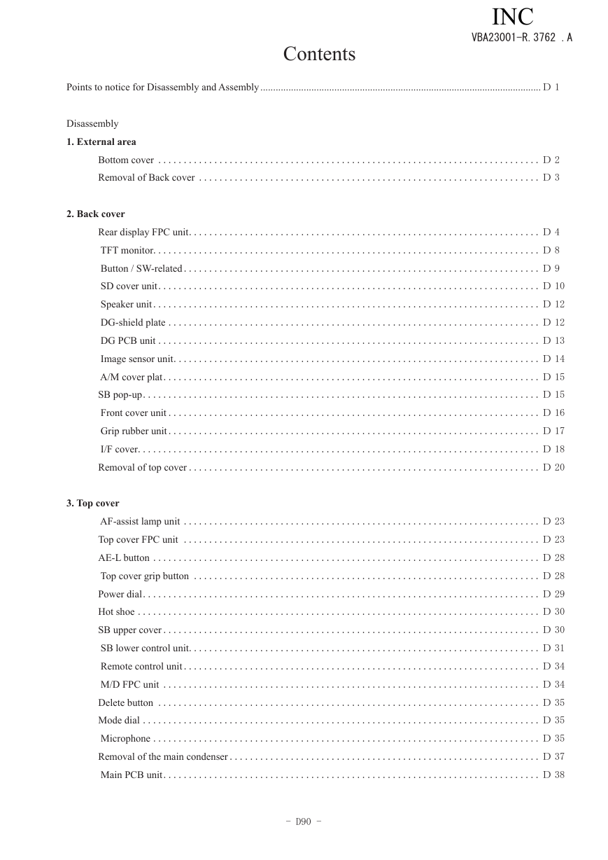
Contents
VBA23001-R.3762 .A
Points to notice for Disassembly and Assembly ..............................................................................................................D 1
Disassembly
1. External area
2. Back cover
Bottom cover ...........................................................................D 2
Removal of Back cover ................................................................... D 3
Rear display FPC unit .....................................................................D 4
TFT monitor............................................................................ D 8
Button / SW-related ...................................................................... D 9
SD cover unit ........................................................................... D 10
Speaker unit ............................................................................D 12
DG-shield plate .........................................................................D 12
DG PCB unit ...........................................................................D 13
Image sensor unit ........................................................................D 14
A/M cover plat ..........................................................................D 15
SB pop-up ..............................................................................D 15
Front cover unit .........................................................................D 16
Grip rubber unit ......................................................................... D 17
I/F cover ............................................................................... D 18
Removal of top cover ..................................................................... D 20
3. Top cover
AF-assist lamp unit ......................................................................D 23
Top cover FPC unit ...................................................................... D 23
AE-L button ............................................................................D 28
Top cover grip button ....................................................................D 28
Power dial .............................................................................. D 29
Hot shoe ...............................................................................D 30
SB upper cover .......................................................................... D 30
SB lower control unit .....................................................................D 31
Remote control unit ...................................................................... D 34
M/D FPC unit ..........................................................................D 34
Delete button ...........................................................................D 35
Mode dial .............................................................................. D 35
Microphone ............................................................................ D 35
Removal of the main condenser .............................................................D 37
Main PCB unit .......................................................................... D 38
- D90 -
INC�
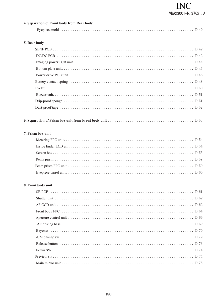
4. Separation of Front body from Rear body
Eyepiece mold ......................................................................... D 40
VBA23001-R.3762 .A
5. Rear body
SB/IF PCB .............................................................................D 42
DC/DC PCB ...........................................................................D 42
Imaging power PCB unit ..................................................................D 44
Bottom plate unit ........................................................................ D 45
Power drive PCB unit .................................................................... D 46
Battery contact-spring .................................................................... D 48
Eyelet .................................................................................D 50
Buzzer unit .............................................................................D 51
Drip-proof sponge .......................................................................D 51
Dust-proof tape .......................................................................... D 52
6. Separation of Prism box unit from Front body unit ...............................................D 53
7. Prism box unit
8. Front body unit
Metering FPC unit .......................................................................D 54
Inside finder LCD unit ....................................................................D 54
Screen box ............................................................................. D 55
Penta prism ............................................................................ D 57
Penta prism FPC unit .....................................................................D 59
Eyepiece barrel unit ......................................................................D 60
SB PCB ...............................................................................D 61
Shutter unit ............................................................................D 62
AF CCD unit ........................................................................... D 62
Front body FPC .........................................................................D 64
Aperture control unit ..................................................................... D 66
AF driving base ........................................................................ D 69
Bayonet ............................................................................... D 70
A/M change sw ......................................................................... D 72
Release button ..........................................................................D 73
F-min SW ............................................................................. D 74
Preview sw .............................................................................D 74
Main mirror unit ........................................................................D 75
- D90 -
INC�
VBA23001-R.3762 .A
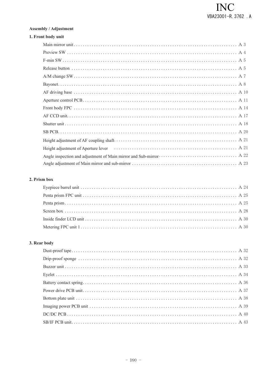
Assembly / Adjustment
1. Front body unit
Main mirror unit .........................................................................A 3
Preview SW ............................................................................ A 4
F-min SW .............................................................................. A 5
Release button ..........................................................................A 5
A/M change SW ......................................................................... A 7
Bayonet ................................................................................ A 8
AF driving base ......................................................................... A 10
Aperture control PCB .....................................................................A 11
Front body FPC .........................................................................A 14
AF CCD unit ............................................................................A 17
Shutter unit .............................................................................A 18
SB PCB ................................................................................A 20
Height adjustment of AF coupling shaft .......................................................A 21
Height adjustment of Aperture lever ....................................................... A 21
Angle inspection and adjustment of Main mirror and Sub-mirror ...................................A 22
Angle adjustment of Main mirror and sub-mirror ...............................................A 23
2. Prism box
3. Rear body
Eyepiece barrel unit ......................................................................A 24
Penta prism FPC unit .....................................................................A 25
Penta prism ............................................................................. A 25
Screen box ............................................................................. A 28
Inside finder LCD unit ....................................................................A 30
Metering FPC unit 1 ......................................................................A 30
Dust-proof tape .......................................................................... A 32
Drip-proof sponge .......................................................................A 32
Buzzer unit .............................................................................A 33
Eyelet .................................................................................A 34
Battery contact spring ..................................................................... A 36
Power drive PCB unit ..................................................................... A 37
Bottom plate unit ........................................................................ A 38
Imaging power PCB unit ..................................................................A 39
DC/DC PCB ............................................................................A 40
SB/IF PCB unit .......................................................................... A 43
- D90 -
INC�
VBA23001-R.3762 .A
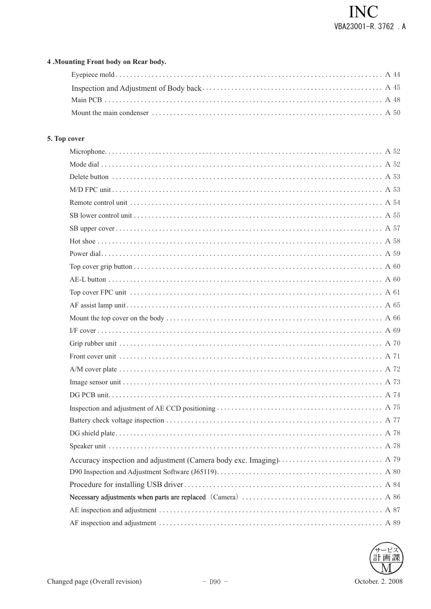
4 .Mounting Front body on Rear body.
Eyepiece mold .......................................................................... A 44
Inspection and Adjustment of Body back ..................................................A 45
Main PCB ............................................................................. A 48
Mount the main condenser ................................................................ A 50
5. Top cover
Microphone ............................................................................. A 52
Mode dial .............................................................................. A 52
Delete button ...........................................................................A 53
M/D FPC unit ...........................................................................A 53
Remote control unit ...................................................................... A 54
SB lower control unit .....................................................................A 55
SB upper cover .......................................................................... A 57
Hot shoe ...............................................................................A 58
Power dial .............................................................................. A 59
Top cover grip button .....................................................................A 60
AE-L button ............................................................................A 60
Top cover FPC unit ...................................................................... A 61
AF assist lamp unit .......................................................................A 65
Mount the top cover on the body ............................................................ A 66
I/F cover ............................................................................... A 69
Grip rubber unit ......................................................................... A 70
Front cover unit .........................................................................A 71
A/M cover plate .........................................................................A 72
Image sensor unit ........................................................................A 73
DG PCB unit ............................................................................A 74
Inspection and adjustment of AE CCD positioning ..............................................A 75
Battery check voltage inspection ............................................................ A 77
DG shield plate ..........................................................................A 78
Speaker unit ............................................................................A 78
Accuracy inspection and adjustment (Camera body exc. Imaging) .............................A 79
D90 Inspection and Adjustment Software (J65119) .............................................. A 80
Procedure for installing USB driver .......................................................A 84
Necessary adjustments when parts are replaced
Necessary adjustments when parts are replaced(Camera) .......................................A 86
AE inspection and adjustment ..............................................................A 87
AF inspection and adjustment .............................................................. A 89
Changed page (Overall revision)
- D90 -
October. 2. 2008
INC�
VBA23001-R.3762 .A
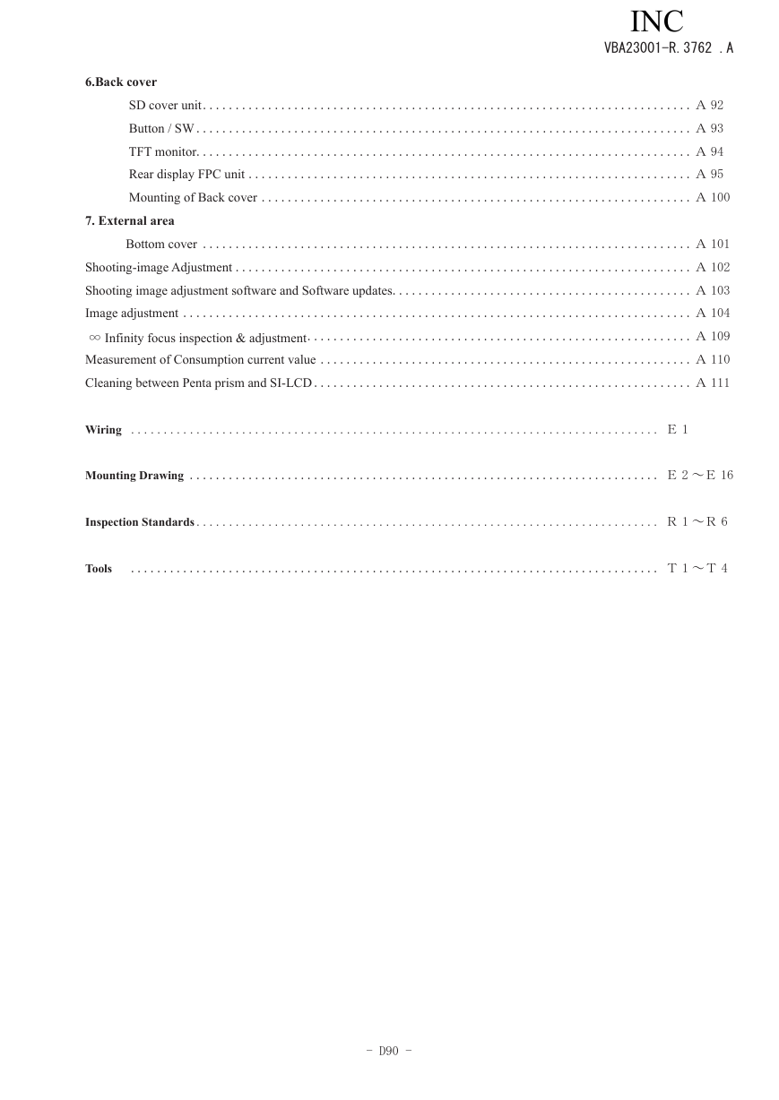
6.Back cover
SD cover unit ........................................................................... A 92
Button / SW ............................................................................A 93
TFT monitor............................................................................ A 94
Rear display FPC unit ....................................................................A 95
Mounting of Back cover ..................................................................A 100
7. External area
Bottom cover ...........................................................................A 101
Shooting-image Adjustment ...................................................................... A 102
Shooting image adjustment software and Software updates .............................................. A 103
Image adjustment .............................................................................. A 104
∞ Infinity focus inspection & adjustment ........................................................... A 109
Measurement of Consumption current value .........................................................A 110
Cleaning between Penta prism and SI-LCD ..........................................................A 111
Wiring ................................................................................. E 1
Mounting Drawing ........................................................................ E 2 ~E 16
Inspection Standards ....................................................................... R 1 ~R 6
Tools ................................................................................. T 1 ~T 4
- D90 -
INC�
Points to notice for Disassembly and Assembly
VBA23001-R.3762 .A
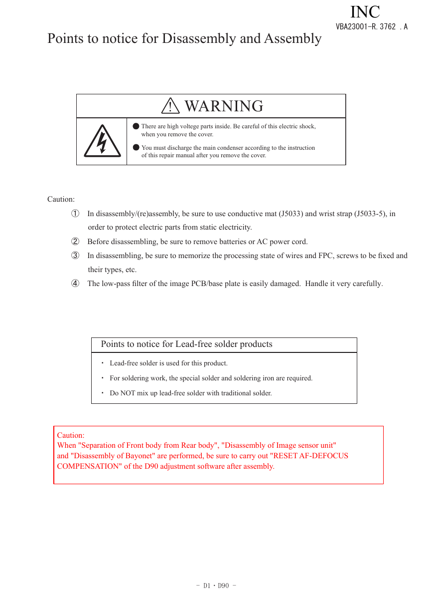
!
WARNING
There are high voltege parts inside. Be careful of this electric shock,
when you remove the cover.
You must discharge the main condenser according to the instruction
of this repair manual after you remove the cover.
Caution:
① In disassembly/(re)assembly, be sure to use conductive mat (J5033) and wrist strap (J5033-5), in
order to protect electric parts from static electricity.
② Before disassembling, be sure to remove batteries or AC power cord.
③ In disassembling, be sure to memorize the processing state of wires and FPC, screws to be fixed and
their types, etc.
④ The low-pass filter of the image PCB/base plate is easily damaged. Handle it very carefully.
Points to notice for Lead-free solder products
・ Lead-free solder is used for this product.
・ For soldering work, the special solder and soldering iron are required.
・ Do NOT mix up lead-free solder with traditional solder.
Caution:
When "Separation of Front body from Rear body", "Disassembly of Image sensor unit"
and "Disassembly of Bayonet" are performed, be sure to carry out "RESET AF-DEFOCUS
COMPENSATION" of the D90 adjustment software after assembly.
- D1 ・ D90 -
INC�
Disassembly
1. External area
Bottom cover
VBA23001-R.3762 .A
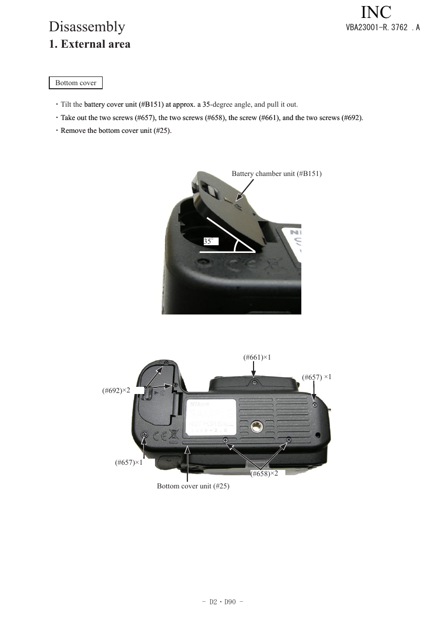
battery cover unit (#B151) at approx. a 35-degree angle, and pull it out.
・Tilt the battery cover unit (#B151) at approx. a 35
Take out the two screws (#657), the two screws (#658), the screw (#661), and the two screws (#692).
・Take out the two screws (#657), the two screws (#658), the screw (#661), and the two screws (#692).
・Remove the bottom cover unit (#25).
Remove the bottom cover unit (#25).
Battery chamber unit (#B151)
35°
(#692)×2
(#661)×1
(#657) ×1
(#657)×1
Bottom cover unit (#25)
(#658)×2
- D2 ・ D90 -
INC�


 2023年江西萍乡中考道德与法治真题及答案.doc
 2012年重庆南川中考生物真题及答案.doc
 2013年江西师范大学地理学综合及文艺理论基础考研真题.doc
 2020年四川甘孜小升初语文真题及答案I卷.doc
 2020年注册岩土工程师专业基础考试真题及答案.doc
 2023-2024学年福建省厦门市九年级上学期数学月考试题及答案.doc
 2021-2022学年辽宁省沈阳市大东区九年级上学期语文期末试题及答案.doc
 2022-2023学年北京东城区初三第一学期物理期末试卷及答案.doc
 2018上半年江西教师资格初中地理学科知识与教学能力真题及答案.doc
 2012年河北国家公务员申论考试真题及答案-省级.doc
 2020-2021学年江苏省扬州市江都区邵樊片九年级上学期数学第一次质量检测试题及答案.doc
 2022下半年黑龙江教师资格证中学综合素质真题及答案.doc