logo资料库

NFCForum-TS-NCI-2.0-170330.pdf

第1页 / 共207页
第2页 / 共207页
第3页 / 共207页
第4页 / 共207页
第5页 / 共207页
第6页 / 共207页
第7页 / 共207页
第8页 / 共207页
资料共207页,剩余部分请下载后查看
NFC Controller Interface (NCI)
[NCI]
NFC ForumTM
RESTRICTIONS ON USE
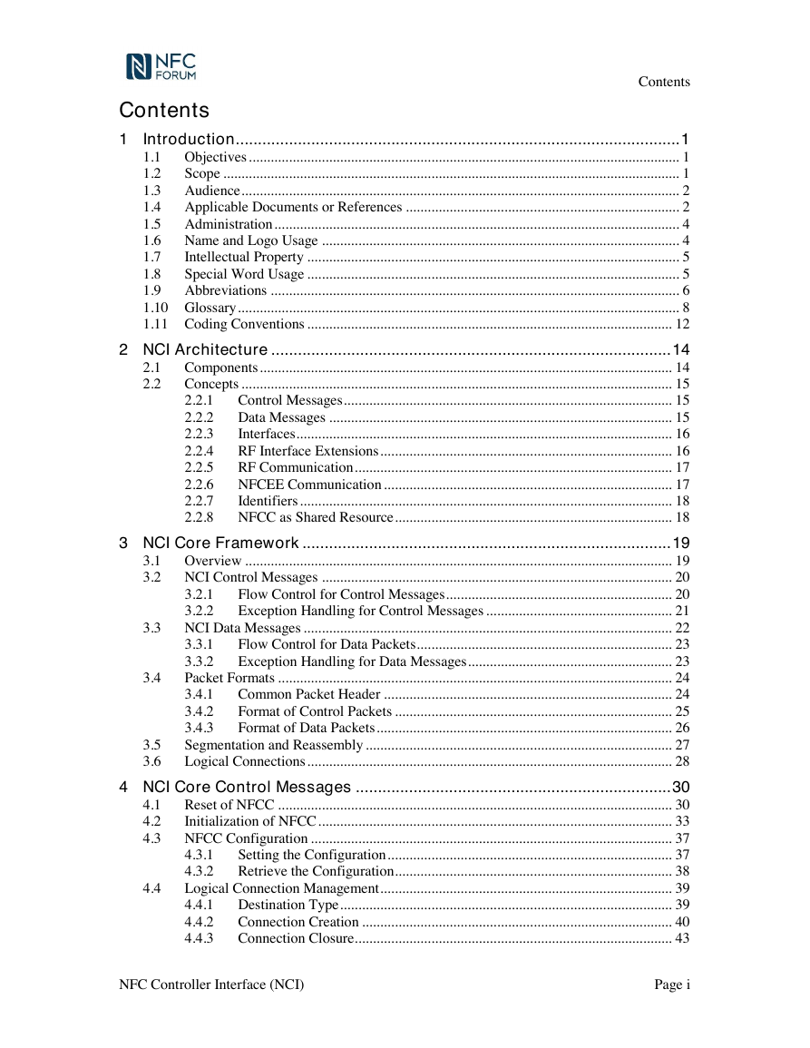
Contents
Figures
Tables
1 Introduction
1.1 Objectives
1.2 Scope
Figure 1: NCI Scope
1.3 Audience
1.4 Applicable Documents or References
1.5 Administration
1.6 Name and Logo Usage
1.7 Intellectual Property
1.8 Special Word Usage
1.9 Abbreviations
Table 1: Abbreviations
1.10 Glossary
DH-NFCEE
HCI-NFCEE
NCI
NDEF-NFCEE
UICC
1.11 Coding Conventions
2 NCI Architecture
2.1 Components
Figure 2: NCI Components
2.2 Concepts
Figure 3: NCI concepts
2.2.1 Control Messages
2.2.2 Data Messages
2.2.3 Interfaces
2.2.4 RF Interface Extensions
2.2.5 RF Communication
2.2.6 NFCEE Communication
2.2.7 Identifiers
2.2.8 NFCC as Shared Resource
3 NCI Core Framework
3.1 Overview
3.2 NCI Control Messages
Figure 4: Control Message Exchange
3.2.1 Flow Control for Control Messages
3.2.2 Exception Handling for Control Messages
3.3 NCI Data Messages
Figure 5: Data Exchange
3.3.1 Flow Control for Data Packets
3.3.2 Exception Handling for Data Messages
3.4 Packet Formats
3.4.1 Common Packet Header
Figure 6: NCI Core Packet Format
Message Type (MT)
Table 2: MT Values
Packet Boundary Flag (PBF)
Table 3: PBF Values
3.4.2 Format of Control Packets
Figure 7: Control Packet Structure
Message Type (MT)
Packet Boundary Flag (PBF)
Group Identifier (GID)
Opcode Identifier (OID)
Payload Length (L)
3.4.3 Format of Data Packets
Figure 8: Data Packet Structure
Message Type (MT)
Packet Boundary Flag (PBF)
Connection Identifier (Conn ID)
Credits (CR)
Payload Length (L)
3.5 Segmentation and Reassembly
The following rules apply to segmenting Control Messages:
The following rules apply to segmenting Data Messages:
3.6 Logical Connections
Dynamic Logical Connection:
Static RF Connection:
Static HCI Connection:
Table 4: Conn ID
4 NCI Core Control Messages
4.1 Reset of NFCC
Table 5: Control Messages to Reset the NFCC
Table 6: NCI Version
Table 7: Configuration Status
4.2 Initialization of NFCC
Table 8: Control Messages to Initialize the NFCC
Table 9: Values for Feature Enable Bit Mapping
Table 10: NFCC Features
4.3 NFCC Configuration
4.3.1 Setting the Configuration
Table 11: Control Messages for Setting Configuration Parameters
4.3.2 Retrieve the Configuration
Table 12: Control Messages for Reading Current Configuration
4.4 Logical Connection Management
4.4.1 Destination Type
Table 13: Destination Types
4.4.2 Connection Creation
Table 14: Control Messages for DH Connection Creation
Table 15: Initial Number of Credits
4.4.3 Connection Closure
Table 17: Control Messages for Connection Closure
4.4.4 Connection Credit Management
Table 18: Control Messages for Connection Credit Management
4.5 Generic Error
Table 19: Control Messages for Generic Error
4.6 Interface Error
Table 20: Control Messages for Interface Error
5 RF Communication
5.1 RF Interface Architecture
Figure 9: RF Interface Architecture
5.2 State Machine
Figure 10: RF Communication State Machine
5.2.1 State RFST_IDLE
5.2.2 State RFST_DISCOVERY
5.2.3 State RFST_W4_ALL_DISCOVERIES
5.2.4 State RFST_W4_HOST_SELECT
5.2.5 State RFST_POLL_ACTIVE
5.2.6 State RFST_LISTEN_ACTIVE
5.2.7 State RFST_LISTEN_SLEEP
5.3 RF Field Information
Table 21: Notification for RF Field information
Table 22: RF Field Status
Table 23: RF Field Information Configuration Parameter
6 RF Communication Configuration
6.1 Configuration Parameters
6.1.1 Poll A Parameters
Table 24: Discovery Configuration Parameters for Poll A
6.1.2 Poll B Parameters
Table 25: Discovery Configuration Parameters for Poll B
Table 26: Values for PB_SENSB_REQ_PARAM
6.1.3 Poll F Parameters
Table 27: Discovery Configuration Parameters for Poll F
6.1.4 Poll ISO-DEP Parameters
Table 28: Discovery Configuration Parameters for ISO-DEP
6.1.5 Poll NFC-DEP Parameters
Table 29: Discovery Configuration Parameters for Poll NFC-DEP
Table 30: Values for PN_ATR_REQ_CONFIG
6.1.6 Poll Active Parameters
Table 31: Poll Mode Discovery Configuration Parameters for Active Mode
6.1.7 Poll V Parameters
Table 32: Discovery Configuration Parameters for Poll V
6.1.8 Listen A Parameters
Table 33: Discovery Configuration Parameters for Listen A
Table 34: LA_SEL_INFO coding
6.1.9 Listen B Parameters
Table 35: Discovery Configuration Parameters for Listen B
Table 36: LB_SENSB_INFO values
Table 37: LB_FWI_ADC_FO values
6.1.10 Listen F Parameters
Table 38: Discovery Configuration Parameters for Listen F
Table 39: Supported Protocols for Listen F
6.1.11 Listen T3T Parameters
Table 40: Discovery Configuration Parameters for Listen T3T
6.1.12 Listen ISO-DEP Parameters
Table 42: Discovery Configuration Parameters for Listen ISO-DEP
Table 43: Values for LI_A_RATS_TC1
6.1.13 Listen NFC-DEP Parameters
Table 44: Discovery Configuration Parameters for Listen NFC-DEP
6.1.14 Common Parameters
Table 46: Common Parameters for Discovery Configuration
Table 47: Values for CON_DISCOVERY_PARAM
6.2 RF Interface Mapping Configuration
Table 48: Control Messages for RF Interface Mapping Configuration
Table 49: Value Field for Mode
6.3 Listen Mode Routing Configuration
6.3.1 Listen Mode Routing Table Design
6.3.2 Configure Listen Mode Routing
Table 50: Control Messages to Configure Listen Mode Routing
Table 53: Listen Mode Routing Entry Types
Table 54: Value Field for Technology-based Routing
Table 55: Value Field for Protocol-based Routing
Table 56: Value Field for AID-based Routing
Table 57: Value Field for System Code-based Routing
Table 58: Value Field for APDU Pattern-based Routing
Table 59: Value Field for Power State
6.3.3 Read Listen Mode Routing
Table 60: Control Messages to Read the NFCC’s Listen Mode Routing
6.3.4 Set Power State for Route Selection
Table 61: Control Messages to Set the NFCC Route Selection Power State
6.3.5 AID-based Route Selection Process
6.3.6 APDU Pattern-based Route Selection Process
6.3.7 System Code-based Route Selection Process
6.3.8 Protocol-based Route Selection Process
6.3.9 Technology-based Route Selection Process
6.3.10 Forced NFCEE Routing
Table 62: Control Messages to Configure Forced NFCEE Routing
7 RF Discovery
7.1 Starting RF Discovery
Table 64: NFCC Configuration Control
Table 65: Value Field for NFCC Configuration Control
Table 66: Control Messages to Start Discovery
Table 67: RF Discovery ID
Table 68: Specific Parameters for NFC-A Poll Mode
Table 69: Specific Parameters for NFC-A Listen Mode
Table 70: Specific Parameters for NFC-B Poll Mode
Table 71: Specific Parameters for NFC-B Listen Mode
Table 72: Specific Parameters for NFC-F Poll Mode
Table 73: Specific Parameters for NFC-F Listen Mode
Table 75: Specific Parameters for NFC-ACM Poll Mode
Table 76: Specific Parameters for NFC-ACM Listen Mode
7.2 Select Discovered Target
Table 77: Control Messages to select a Discovered Target
7.3 RF Interface Activation and Deactivation
7.3.1 RF Interface Activation Notification
Table 78: Notification for RF Interface activation
7.3.2 RF Interface Deactivation
Table 79: Control Messages for RF Interface Deactivation
Table 80: Deactivation Types
Table 81: Deactivation Reasons
7.4 RF Interface Extension Starting and Stopping
7.4.1 RF Interface Extension Start
7.4.2 RF Interface Extension Stop
7.5 RF Discovery Request from NFCEEs
Table 84: Notification for RF Discovery Request from NFCEE
Table 86: Value Field for RF Discovery Request Information
7.6 RF NFCEE Action
Table 87: Notification to Report an NFCEE Action
Table 88: Trigger in NFCEE Action Notification
Table 89: RF_NFCEE_ACTION configuration parameter
8 RF Interfaces
8.1 NFCEE Direct RF Interface
8.1.1 Discovery and Interface Activation
8.1.2 Interface Deactivation
8.2 Frame RF Interface
8.2.1 Data Mapping between the DH and RF
8.2.1.1 Data from the DH to RF
Figure 11: Format for Frame RF Interface (NFC-A) for Transmission
Figure 12: Format for Frame RF Interface (NFC-B) for Transmission
Figure 13: Format for Frame RF Interface (NFC-F) for Transmission
Figure 14: Format for Frame RF Interface (NFC-V) for Transmission
8.2.1.2 Data from RF to the DH
Figure 15: Format for Frame RF Interface (NFC-A) for Reception
Figure 16: Format for Frame RF Interface (NFC-B) for Reception
Figure 17: Format for Frame RF Interface (NFC-F) for Reception
Figure 18: Format for Frame RF Interface (NFC-V) for Reception
8.2.2 Frame RF Interface specific Control Messages
8.2.2.1 RF Communication Parameter Update
Table 90: Control Messages for RF Parameter Update
Table 92: NFC-B Data Exchange Configuration Parameter
8.2.2.2 Request Type 3 Tag Polling
Table 93: Control Messages to Request the NFCC to send a Type 3 Tag Polling Command
8.2.3 Poll-side Frame RF Interface Management
8.2.3.1 Discovery Configuration
8.2.3.2 Discovery and Interface Activation
8.2.3.3 Interface Deactivation
8.2.3.4 Failures during Data Exchange
8.2.4 Listen-side Frame RF Interface Management
8.2.4.1 Discovery Configuration
8.2.4.2 Discovery and Interface Activation
Table 94: Pre-activation states and the split of commands between NFCC and DH
8.2.4.3 Interface Deactivation
8.2.4.4 Failures during Data Exchange
8.3 ISO-DEP RF Interface
8.3.1 Data Mapping between the DH and RF
8.3.1.1 Data from the DH to RF
Figure 19: Format for ISO-DEP RF Interface for Transmission
8.3.1.2 Data from RF to the DH
Figure 20: Format for ISO-DEP RF Interface for Reception
8.3.2 Poll-side ISO-DEP RF Interface Management
8.3.2.1 Discovery Configuration
8.3.2.2 Discovery and Interface Activation
Detailed ISO-DEP RF Interface activation handling in the NFCC
For NFC-A:
Table 95: Activation Parameters for NFC-A/ISO-DEP Poll Mode
For NFC-B:
Table 96: Activation Parameters for NFC-B/ISO-DEP Poll Mode
8.3.2.3 Interface Deactivation
8.3.2.4 Failures during Data Exchange
8.3.2.5 ISO-DEP R(NAK) Presence Check
Table 97: Control Messages to Request the NFCC to send an ISO-DEP R(NAK)
8.3.3 Listen-side ISO-DEP RF Interface Management
8.3.3.1 Discovery Configuration
8.3.3.2 Discovery and Interface Activation
Detailed ISO-DEP RF Interface activation handling in the NFCC:
For NFC-A:
Table 98: Activation Parameters for NFC-A/ISO-DEP Listen Mode
For NFC-B:
Table 99: Activation Parameters for NFC-B/ISO-DEP Listen Mode
8.3.3.3 Interface Deactivation
8.3.3.4 Failures during Data Exchange
8.4 NFC-DEP RF Interface
8.4.1 Data Mapping between the DH and RF
8.4.1.1 Data from the DH to RF
Figure 21: Format for NFC-DEP RF Interface for Transmission
8.4.1.2 Data from RF to the DH
Figure 22: Format for NFC-DEP RF Interface for Reception
8.4.2 NFC-DEP RF Interface Configuration
Table 100: Specific Parameters for NFC-DEP RF Interface
Table 101: NFC-DEP Operation Parameter
8.4.3 Poll-side NFC-DEP RF Interface Management
8.4.3.1 Discovery Configuration
8.4.3.2 Discovery and Interface Activation
Table 102: Activation Parameters for NFC-DEP Poll Mode
8.4.3.3 Interface Deactivation
8.4.3.4 Failures during Data Exchange
8.4.4 Listen-side NFC-DEP RF Interface Management
8.4.4.1 Discovery Configuration
8.4.4.2 Discovery and Interface Activation
Table 103: Activation Parameters for NFC-DEP Listen Mode
8.4.4.3 Interface Deactivation
8.4.4.4 Failures during Data Exchange
8.5 NDEF RF Interface
8.5.1 NCI Data Message Format
8.5.1.1 NDEF Get
8.5.1.2 NDEF Put
8.5.1.3 NDEF Write Lock
8.5.2 NDEF RF Interface specific Control Messages
8.5.2.1 NDEF Abort
8.5.3 NDEF RF Interface Management
8.5.3.1 Discovery Configuration
8.5.3.2 Discovery and Interface Activation
8.5.3.3 Interface Deactivation
8.5.4 Failures during Data Exchange
9 RF Interface Extensions
9.1 Frame Aggregation RF Interface Extension
9.1.1 Startup conditions
9.1.2 Starting the RF Interface Extension
Table 111: Frame Aggregation RF Interface Extension Start Parameter
9.1.3 RF Interface Extension functionality
9.1.3.1 NCI Data Message Format
Figure 23: Format for Data Message from DH to NFCC
Figure 24: Format for Data Message from NFCC to DH
Table 112: Aggregation TLV Objects
9.1.3.2 Aborting a Pending Transmission
Table 113: Control Messages for Aggregation Abort
9.1.3.3 Error Handling
9.1.4 Stopping the RF Interface Extension
9.2 LLCP Symmetry RF Interface Extension
9.2.1 Startup conditions
9.2.2 Starting the RF Interface Extension
Table 114: LLCP Symmetry RF Interface Extension Start Parameter
9.2.3 RF Interface Extension functionality
9.2.3.1 Configuration
Table 115: LLCP Version Parameter
9.2.3.2 Error Handling
9.2.4 Stopping the RF Interface Extension
10 NFCEE Discovery and Mode Set
10.1 NFCEE ID
Table 116: NFCEE IDs
10.2 NFCEE Discovery
Table 117: Control Messages for NFCEE Discovery
Table 118: TLV Coding for NFCEE Discovery
Table 119: Value Field for T3T Command Set Interface Supplementary Information
Figure 25: NFCEE State Transitions
10.2.1 HCI-NFCEE Specific Handling
10.2.2 NDEF-NFCEE Specific Handling
10.3 NFCEE Enabling and Disabling
Table 121: Control Messages to Enable and Disable a Connected NFCEE
10.3.1 HCI-NFCEE Specific Handling
10.4 NDEF-NFCEE
10.5 NFCEE Status
Table 122: Control Messages to report the status of an NFCEE
10.5.1 HCI- NFCEE Specific Handling
10.6 NFCEE Power Supply and Communication Link Control
Table 123: Control Messages to constrain the Power Supply and link of an NFCEE
10.6.1 HCI- NFCEE Specific Handling
11 NFCEE Interfaces
11.1 APDU NFCEE Interface
11.1.1 Data Exchange
11.1.1.1 Format for Data Messages sent from DH to NFCC
Figure 26: Mapping of Command APDU
11.1.1.2 Format for Data Messages sent from NFCC to DH
Figure 27: Mapping of Response APDU
11.1.2 Failures during Data Exchange
11.2 Type 3 Tag Command Set NFCEE Interface
11.2.1 Data Exchange
Figure 28: Data Message Format for Type 3 Tag Command Set Interface
11.2.1.1 Polling Command and Response
11.3 Transparent NFCEE Interface
11.3.1 Data Exchange
12 Transport Mappings
12.1 UART Transport
12.2 I2C Transport
12.3 Half Duplex SPI Transport
12.3.1 Physical
12.3.1.1 SPI Modes
Table 124: SPI modes
Figure 29: SPI Operation
12.3.2 Data Transfer
12.3.2.1 Data Transfer from DH to NFCC
Table 125: SPI Header Coding (DH to NFCC) without CRC
Figure 30: SPI Data Transfer from the DH to the NFCC without CRC
Table 126: SPI Header Coding (DH to NFCC) with CRC
Figure 31: SPI Data Transfer from the DH to the NFCC with CRC
12.3.2.2 Data Transfer from NFCC to DH
Table 127: SPI Header Coding (NFCC to DH) without CRC
Figure 32: SPI Data Transfer from the NFCC to the DH without CRC
Table 128: SPI Header Coding (NFCC to DH) with CRC
Figure 33: SPI Data Transfer from the NFCC to the DH with CRC
12.3.2.3 Race Condition
Figure 34: SPI Race Condition 1
Figure 35: SPI Race Condition 2
13 Testing
13.1 Local Loopback Mode
A. Exhibit A
B. Common Tables
Table 129: Status Codes
Table 130: RF Technologies
Table 131: RF Technology and Mode
Table 132: Bit Rates
Table 133: RF Protocols
Table 134: RF Interfaces
Table 136: NFCEE Protocols / Interfaces
Table 137: Length Reduction Values
Table 138: Configuration Parameter Tags
Table 139: GID and OID Definitions
C. Revision History
Table 140: Revision History
NFC Controller Interface (NCI) Technical Specification Version 2.0 2017-03-30 [NCI] NFC ForumTM
RESTRICTIONS ON USE This specification is copyright © 2005-2017 by the NFC Forum, and was made available pursuant to a license agreement entered into between the recipient (Licensee) and NFC Forum, Inc. (Licensor) and may be used only by Licensee, and in compliance with the terms of that license agreement (License). If you are not the Licensee, you may read this Specification, but are not authorized to implement or make any other use of this specification. However, you may obtain a copy of this Specification and implementation rights at the following page of Licensor's website: http://www.nfc-forum.org/specs/spec_license after entering into and agreeing to such license terms as Licensor is then requiring. On the date that this specification was downloaded by Licensee, the non-implementation terms of that license were as follows: 1. LICENSE GRANT Licensor hereby grants Licensee the right, without charge, to copy (for internal purposes only, except with respect to the elements listed on Exhibit A) and share this Specification with Licensee's members, employees and (to the extent related to Licensees’ use of this Specification) consultants. This license grant does not include the right to sublicense, modify or create derivative works based upon any portion of the Specification, except for the elements listed on Exhibit A. 2. NO WARRANTIES. THE SPECIFICATION IS PROVIDED "AS IS", WITHOUT WARRANTY OF ANY KIND, EXPRESS OR IMPLIED, INCLUDING BUT NOT LIMITED TO WARRANTIES OF MERCHANTABILITY, FITNESS FOR A PARTICULAR PURPOSE, ACCURACY, COMPLETENESS AND NONINFRINGEMENT OF THIRD PARTY RIGHTS. IN NO EVENT SHALL LICENSOR, ITS MEMBERS OR ITS CONTRIBUTORS BE LIABLE FOR ANY CLAIM, OR ANY DIRECT, SPECIAL, INDIRECT OR CONSEQUENTIAL DAMAGES, OR ANY DAMAGES WHATSOEVER RESULTING FROM LOSS OF USE, DATA OR PROFITS, WHETHER IN AN ACTION OF CONTRACT, NEGLIGENCE OR OTHER TORTIOUS ACTION, ARISING OUT OF OR IN CONNECTION WITH THE USE OR PERFORMANCE OF THE SPECIFICATION. 3. THIRD PARTY RIGHTS. Without limiting the generality of Section 2 above, LICENSOR ASSUMES NO RESPONSIBILITY TO COMPILE, CONFIRM, UPDATE OR MAKE PUBLIC ANY THIRD PARTY ASSERTIONS OF PATENT OR OTHER INTELLECTUAL PROPERTY RIGHTS THAT MIGHT NOW OR IN THE FUTURE BE INFRINGED BY AN IMPLEMENTATION OF THE SPECIFICATION IN ITS CURRENT, OR IN ANY FUTURE FORM. IF ANY SUCH RIGHTS ARE DESCRIBED ON THE SPECIFICATION, LICENSOR TAKES NO POSITION AS TO THE VALIDITY OR INVALIDITY OF SUCH ASSERTIONS, OR THAT ALL SUCH ASSERTIONS THAT HAVE OR MAY BE MADE ARE SO LISTED. 4. TERMINATION OF LICENSE. In the event of a breach of this Agreement by Licensee or any of its employees or members, Licensor shall give Licensee written notice and an opportunity to cure. If the breach is not cured within thirty (30) days after written notice, or if the breach is of a nature that cannot be cured, then Licensor may immediately or thereafter terminate the licenses granted in this Agreement. 5. MISCELLANEOUS. All notices required under this Agreement shall be in writing, and shall be deemed effective five days from deposit in the mails. Notices and correspondence to the NFC Forum address as it appears below. This Agreement shall be construed and interpreted under the internal laws of the United States and the Commonwealth of Massachusetts, without giving effect to its principles of conflict of law. NFC Forum, Inc. 401 Edgewater Place, Suite 600 Wakefield, MA, USA 01880
Contents Contents 1 Introduction .................................................................................................... 1 1.1 Objectives ...................................................................................................................... 1 1.2 Scope ............................................................................................................................. 1 1.3 Audience ........................................................................................................................ 2 1.4 Applicable Documents or References ........................................................................... 2 1.5 Administration ............................................................................................................... 4 1.6 Name and Logo Usage .................................................................................................. 4 Intellectual Property ...................................................................................................... 5 1.7 1.8 Special Word Usage ...................................................................................................... 5 1.9 Abbreviations ................................................................................................................ 6 1.10 Glossary ......................................................................................................................... 8 1.11 Coding Conventions .................................................................................................... 12 2.1 2.2 2 NCI Architecture .......................................................................................... 14 Components ................................................................................................................. 14 Concepts ...................................................................................................................... 15 Control Messages .......................................................................................... 15 2.2.1 Data Messages .............................................................................................. 15 2.2.2 2.2.3 Interfaces ....................................................................................................... 16 RF Interface Extensions ................................................................................ 16 2.2.4 RF Communication ....................................................................................... 17 2.2.5 NFCEE Communication ............................................................................... 17 2.2.6 2.2.7 Identifiers ...................................................................................................... 18 NFCC as Shared Resource ............................................................................ 18 2.2.8 3.2.1 3.2.2 3 NCI Core Framework ................................................................................... 19 3.1 Overview ..................................................................................................................... 19 3.2 NCI Control Messages ................................................................................................ 20 Flow Control for Control Messages .............................................................. 20 Exception Handling for Control Messages ................................................... 21 3.3 NCI Data Messages ..................................................................................................... 22 Flow Control for Data Packets ...................................................................... 23 3.3.1 3.3.2 Exception Handling for Data Messages ........................................................ 23 Packet Formats ............................................................................................................ 24 3.4.1 Common Packet Header ............................................................................... 24 Format of Control Packets ............................................................................ 25 3.4.2 3.4.3 Format of Data Packets ................................................................................. 26 Segmentation and Reassembly .................................................................................... 27 Logical Connections .................................................................................................... 28 3.4 3.5 3.6 4 NCI Core Control Messages ....................................................................... 30 Reset of NFCC ............................................................................................................ 30 4.1 4.2 Initialization of NFCC ................................................................................................. 33 4.3 NFCC Configuration ................................................................................................... 37 Setting the Configuration .............................................................................. 37 4.3.1 4.3.2 Retrieve the Configuration ............................................................................ 38 Logical Connection Management ................................................................................ 39 4.4.1 Destination Type ........................................................................................... 39 Connection Creation ..................................................................................... 40 4.4.2 4.4.3 Connection Closure....................................................................................... 43 4.4 NFC Controller Interface (NCI) Page i
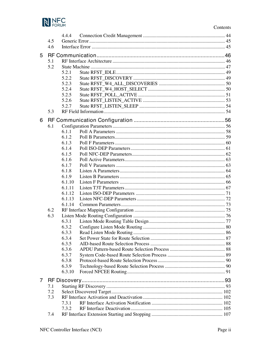
Contents 4.4.4 Connection Credit Management ................................................................... 44 4.5 Generic Error ............................................................................................................... 45 4.6 Interface Error ............................................................................................................. 45 5.1 5.2 5 RF Communication ...................................................................................... 46 RF Interface Architecture ............................................................................................ 46 State Machine .............................................................................................................. 47 State RFST_IDLE ......................................................................................... 49 5.2.1 5.2.2 State RFST_DISCOVERY ........................................................................... 49 State RFST_W4_ALL_DISCOVERIES ...................................................... 50 5.2.3 State RFST_W4_HOST_SELECT ............................................................... 50 5.2.4 State RFST_POLL_ACTIVE ....................................................................... 51 5.2.5 5.2.6 State RFST_LISTEN_ACTIVE ................................................................... 53 5.2.7 State RFST_LISTEN_SLEEP ...................................................................... 54 RF Field Information ................................................................................................... 54 5.3 6.1 6 RF Communication Configuration ............................................................. 56 Configuration Parameters ............................................................................................ 56 Poll A Parameters ......................................................................................... 58 6.1.1 Poll B Parameters.......................................................................................... 59 6.1.2 Poll F Parameters .......................................................................................... 60 6.1.3 6.1.4 Poll ISO-DEP Parameters ............................................................................. 61 Poll NFC-DEP Parameters ............................................................................ 62 6.1.5 Poll Active Parameters .................................................................................. 63 6.1.6 Poll V Parameters ......................................................................................... 63 6.1.7 6.1.8 Listen A Parameters ...................................................................................... 64 6.1.9 Listen B Parameters ...................................................................................... 65 6.1.10 Listen F Parameters ...................................................................................... 66 6.1.11 Listen T3T Parameters .................................................................................. 67 6.1.12 Listen ISO-DEP Parameters ......................................................................... 71 6.1.13 Listen NFC-DEP Parameters ........................................................................ 72 6.1.14 Common Parameters ..................................................................................... 73 RF Interface Mapping Configuration .......................................................................... 75 Listen Mode Routing Configuration ........................................................................... 76 Listen Mode Routing Table Design .............................................................. 77 6.3.1 Configure Listen Mode Routing ................................................................... 80 6.3.2 6.3.3 Read Listen Mode Routing ........................................................................... 86 Set Power State for Route Selection ............................................................. 87 6.3.4 AID-based Route Selection Process ............................................................. 88 6.3.5 APDU Pattern-based Route Selection Process ............................................. 88 6.3.6 6.3.7 System Code-based Route Selection Process ............................................... 89 Protocol-based Route Selection Process ....................................................... 90 6.3.8 6.3.9 Technology-based Route Selection Process ................................................. 90 6.3.10 Forced NFCEE Routing ................................................................................ 91 6.2 6.3 7.1 7.2 7.3 7 RF Discovery ................................................................................................ 93 Starting RF Discovery ................................................................................................. 93 Select Discovered Target ........................................................................................... 102 RF Interface Activation and Deactivation ................................................................. 102 7.3.1 RF Interface Activation Notification .......................................................... 102 7.3.2 RF Interface Deactivation ........................................................................... 105 RF Interface Extension Starting and Stopping .......................................................... 107 7.4 NFC Controller Interface (NCI) Page ii
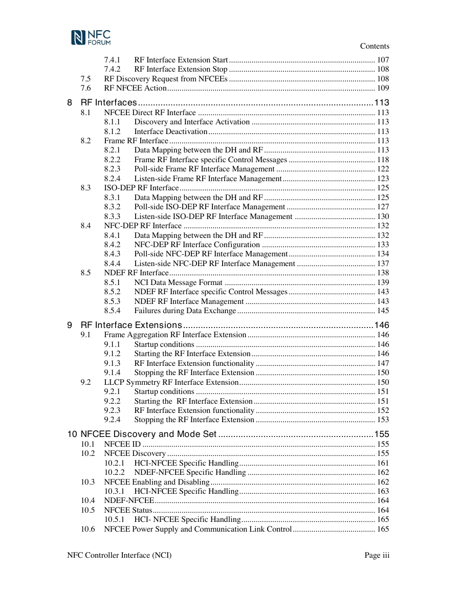
Contents RF Interface Extension Start ....................................................................... 107 7.4.1 7.4.2 RF Interface Extension Stop ....................................................................... 108 RF Discovery Request from NFCEEs ....................................................................... 108 RF NFCEE Action ..................................................................................................... 109 7.5 7.6 8.2 8.3 8 RF Interfaces .............................................................................................. 113 8.1 NFCEE Direct RF Interface ...................................................................................... 113 Discovery and Interface Activation ............................................................ 113 8.1.1 Interface Deactivation ................................................................................. 113 8.1.2 Frame RF Interface .................................................................................................... 113 Data Mapping between the DH and RF ...................................................... 113 8.2.1 Frame RF Interface specific Control Messages .......................................... 118 8.2.2 8.2.3 Poll-side Frame RF Interface Management ................................................ 122 8.2.4 Listen-side Frame RF Interface Management ............................................. 123 ISO-DEP RF Interface ............................................................................................... 125 Data Mapping between the DH and RF ...................................................... 125 8.3.1 8.3.2 Poll-side ISO-DEP RF Interface Management ........................................... 127 Listen-side ISO-DEP RF Interface Management ....................................... 130 8.3.3 8.4 NFC-DEP RF Interface ............................................................................................. 132 Data Mapping between the DH and RF ...................................................... 132 NFC-DEP RF Interface Configuration ....................................................... 133 Poll-side NFC-DEP RF Interface Management .......................................... 134 Listen-side NFC-DEP RF Interface Management ...................................... 137 8.5 NDEF RF Interface.................................................................................................... 138 NCI Data Message Format ......................................................................... 139 NDEF RF Interface specific Control Messages .......................................... 143 NDEF RF Interface Management ............................................................... 143 Failures during Data Exchange ................................................................... 145 8.4.1 8.4.2 8.4.3 8.4.4 8.5.1 8.5.2 8.5.3 8.5.4 9.1 9 RF Interface Extensions ............................................................................ 146 Frame Aggregation RF Interface Extension .............................................................. 146 Startup conditions ....................................................................................... 146 9.1.1 9.1.2 Starting the RF Interface Extension ............................................................ 146 RF Interface Extension functionality .......................................................... 147 9.1.3 9.1.4 Stopping the RF Interface Extension .......................................................... 150 LLCP Symmetry RF Interface Extension .................................................................. 150 9.2.1 Startup conditions ....................................................................................... 151 Starting the RF Interface Extension ........................................................... 151 9.2.2 RF Interface Extension functionality .......................................................... 152 9.2.3 9.2.4 Stopping the RF Interface Extension .......................................................... 153 9.2 10 NFCEE Discovery and Mode Set .............................................................. 155 10.1 NFCEE ID ................................................................................................................. 155 10.2 NFCEE Discovery ..................................................................................................... 155 10.2.1 HCI-NFCEE Specific Handling .................................................................. 161 10.2.2 NDEF-NFCEE Specific Handling .............................................................. 162 10.3 NFCEE Enabling and Disabling ................................................................................ 162 10.3.1 HCI-NFCEE Specific Handling .................................................................. 163 10.4 NDEF-NFCEE ........................................................................................................... 164 10.5 NFCEE Status ............................................................................................................ 164 10.5.1 HCI- NFCEE Specific Handling ................................................................. 165 10.6 NFCEE Power Supply and Communication Link Control ........................................ 165 NFC Controller Interface (NCI) Page iii
Contents 10.6.1 HCI- NFCEE Specific Handling ................................................................. 167 11 NFCEE Interfaces ...................................................................................... 168 11.1 APDU NFCEE Interface ........................................................................................... 168 11.1.1 Data Exchange ............................................................................................ 168 11.1.2 Failures during Data Exchange ................................................................... 170 11.2 Type 3 Tag Command Set NFCEE Interface ............................................................ 170 11.2.1 Data Exchange ............................................................................................ 170 11.3 Transparent NFCEE Interface ................................................................................... 171 11.3.1 Data Exchange ............................................................................................ 171 12 Transport Mappings .................................................................................. 172 12.1 UART Transport ........................................................................................................ 172 12.2 I2C Transport ............................................................................................................ 173 12.3 Half Duplex SPI Transport ........................................................................................ 173 12.3.1 Physical ....................................................................................................... 173 12.3.2 Data Transfer .............................................................................................. 174 13 Testing ........................................................................................................ 180 13.1 Local Loopback Mode ............................................................................................... 180 A. Exhibit A ..................................................................................................... 181 B. Common Tables ......................................................................................... 182 C. Revision History ........................................................................................ 194 NFC Controller Interface (NCI) Page iv
Figures Figures Figure 1: NCI Scope ........................................................................................................................ 1 Figure 2: NCI Components ........................................................................................................... 14 Figure 3: NCI concepts .................................................................................................................. 15 Figure 4: Control Message Exchange ............................................................................................ 20 Figure 5: Data Exchange ............................................................................................................... 22 Figure 6: NCI Core Packet Format ................................................................................................ 24 Figure 7: Control Packet Structure ................................................................................................ 25 Figure 8: Data Packet Structure ..................................................................................................... 26 Figure 9: RF Interface Architecture .............................................................................................. 46 Figure 10: RF Communication State Machine .............................................................................. 48 Figure 11: Format for Frame RF Interface (NFC-A) for Transmission ...................................... 114 Figure 12: Format for Frame RF Interface (NFC-B) for Transmission ....................................... 115 Figure 13: Format for Frame RF Interface (NFC-F) for Transmission ....................................... 115 Figure 14: Format for Frame RF Interface (NFC-V) for Transmission ...................................... 115 Figure 15: Format for Frame RF Interface (NFC-A) for Reception ............................................ 116 Figure 16: Format for Frame RF Interface (NFC-B) for Reception ............................................ 117 Figure 17: Format for Frame RF Interface (NFC-F) for Reception ............................................ 117 Figure 18: Format for Frame RF Interface (NFC-V) for Reception ............................................ 117 Figure 19: Format for ISO-DEP RF Interface for Transmission ................................................. 126 Figure 20: Format for ISO-DEP RF Interface for Reception ...................................................... 127 Figure 21: Format for NFC-DEP RF Interface for Transmission................................................ 132 Figure 22: Format for NFC-DEP RF Interface for Reception ..................................................... 133 Figure 23: Format for Data Message from DH to NFCC ............................................................ 147 Figure 24: Format for Data Message from NFCC to DH ............................................................ 148 Figure 25: NFCEE State Transitions ........................................................................................... 161 Figure 26: Mapping of Command APDU ................................................................................... 169 Figure 27: Mapping of Response APDU ..................................................................................... 170 Figure 28: Data Message Format for Type 3 Tag Command Set Interface ................................. 171 Figure 29: SPI Operation ............................................................................................................. 174 Figure 30: SPI Data Transfer from the DH to the NFCC without CRC ...................................... 175 Figure 31: SPI Data Transfer from the DH to the NFCC with CRC ........................................... 176 Figure 32: SPI Data Transfer from the NFCC to the DH without CRC ...................................... 177 Figure 33: SPI Data Transfer from the NFCC to the DH with CRC ........................................... 178 NFC Controller Interface (NCI) Page v
Figures Figure 34: SPI Race Condition 1 ................................................................................................. 178 Figure 35: SPI Race Condition 2 ................................................................................................. 179 NFC Controller Interface (NCI) Page vi
分享到:
收藏