RTL8309G-GR
SINGLE-CHIP 9-PORT 10/100MBPS
SWITCH CONTROLLER
DATASHEET
(CONFIDENTIAL: Development Partners Only)
Rev. 1.0
12 August 2008
Track ID: JATR-1076-21
Realtek Semiconductor Corp.
No. 2, Innovation Road II, Hsinchu Science Park, Hsinchu 300, Taiwan
Tel.: +886-3-578-0211. Fax: +886-3-577-6047
www.realtek.com
�
RTL8309G
Datasheet
COPYRIGHT
©2008 Realtek Semiconductor Corp. All rights reserved. No part of this document may be reproduced,
transmitted, transcribed, stored in a retrieval system, or translated into any language in any form or by any
means without the written permission of Realtek Semiconductor Corp.
DISCLAIMER
Realtek provides this document “as is”, without warranty of any kind, neither expressed nor implied,
including, but not limited to, the particular purpose. Realtek may make improvements and/or changes in
this document or in the product described in this document at any time. This document could include
technical inaccuracies or typographical errors.
TRADEMARKS
Realtek is a trademark of Realtek Semiconductor Corporation. Other names mentioned in this document
are trademarks/registered trademarks of their respective owners.
USING THIS DOCUMENT
This document is intended for use by the software engineer when programming for Realtek RTL8309G
switch controller chips.
Though every effort has been made to assure that this document is current and accurate, more information
may have become available subsequent to the production of this guide. In that event, please contact your
Realtek representative for additional information that may help in the development process.
REVISION HISTORY
Revision
1.0
1.1
Release Date
2008/08/12
2008/08/22
Summary
First release.
Correct operating temperature
Single-Chip 9-Port 10/100Mbps Switch Controller
ii
Track ID: JATR-1076-21 Rev. 1.0
�
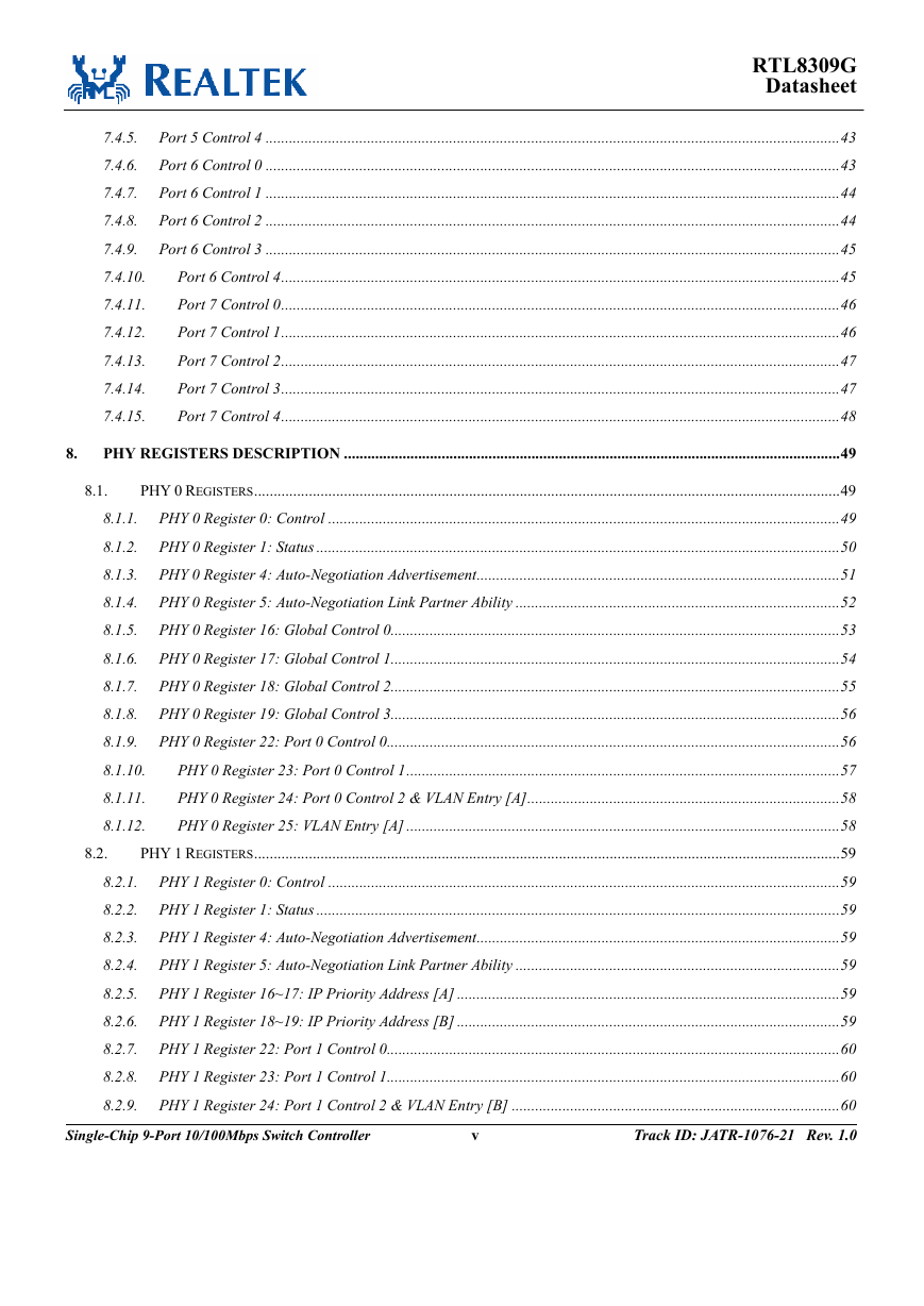
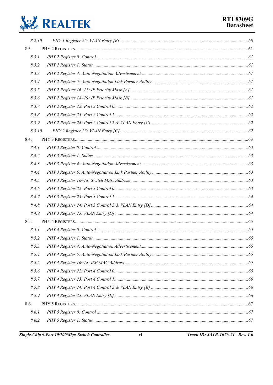
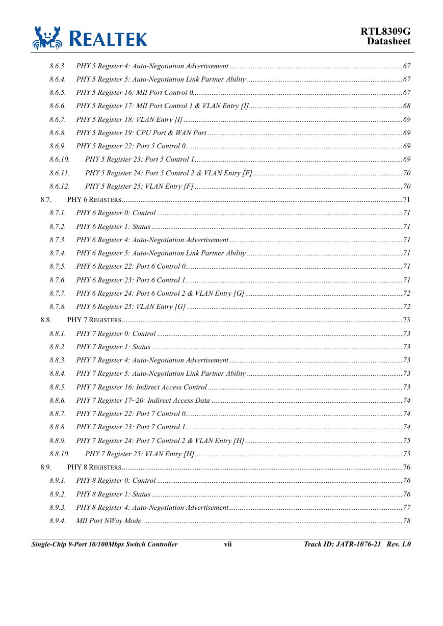
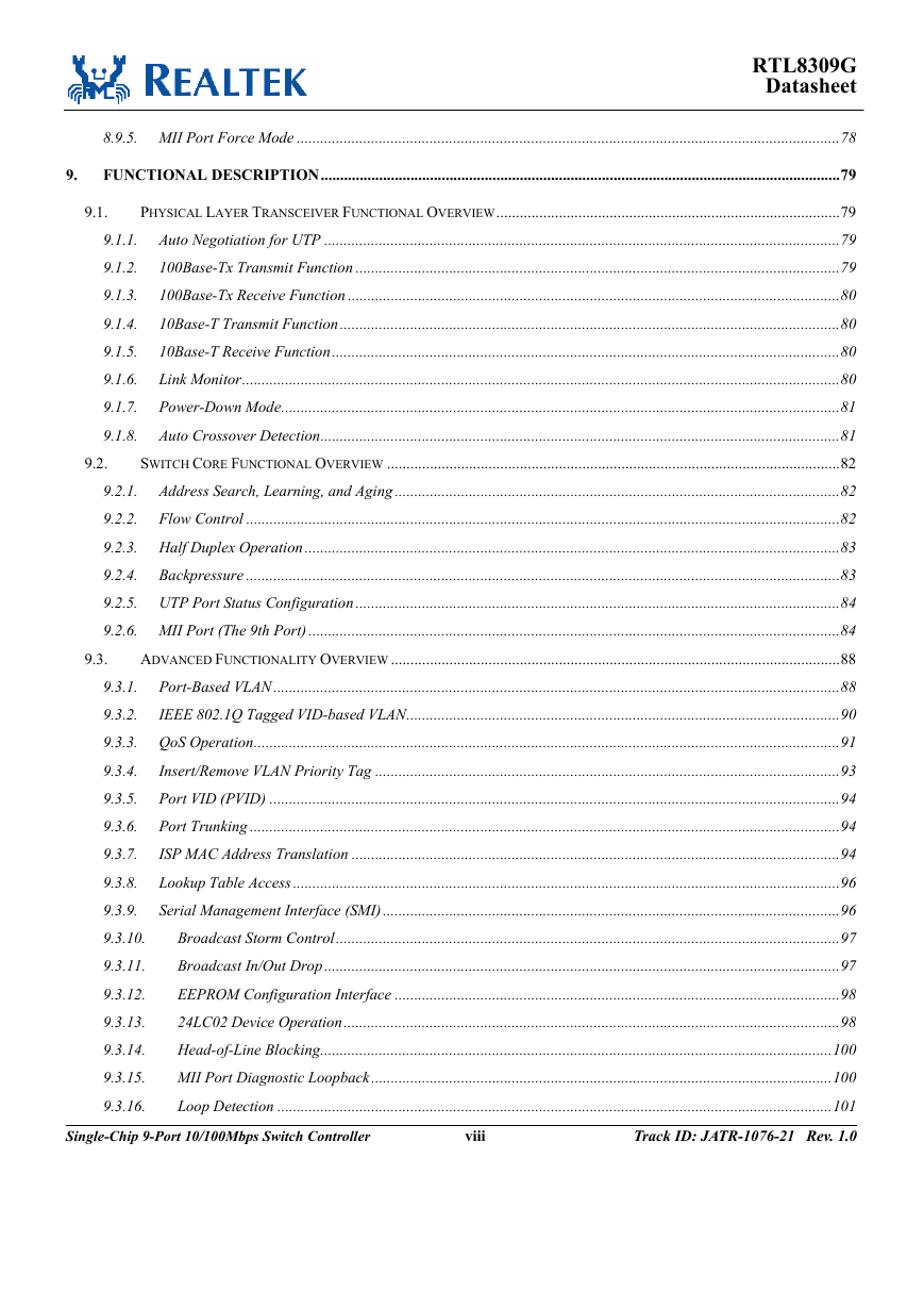
Table of Contents
RTL8309G
Datasheet
1. GENERAL DESCRIPTION..............................................................................................................................................1
2.
3.
4.
5.
FEATURES.........................................................................................................................................................................4
SYSTEM APPLICATIONS...............................................................................................................................................5
BLOCK DIAGRAM...........................................................................................................................................................6
PIN ASSIGNMENTS .........................................................................................................................................................7
5.1.
5.2.
PACKAGE IDENTIFICATION...........................................................................................................................................7
PIN ASSIGNMENTS TABLE............................................................................................................................................8
6.
PIN DESCRIPTIONS.......................................................................................................................................................10
6.1.
6.2.
6.3.
6.4.
6.5.
6.6.
6.7.
MEDIA CONNECTION PINS .........................................................................................................................................10
MII PORT MAC INTERFACE PINS...............................................................................................................................11
MISCELLANEOUS PINS ...............................................................................................................................................12
PORT LED PINS .........................................................................................................................................................13
SERIAL EEPROM AND SMI PINS ..............................................................................................................................16
STRAPPING PINS.........................................................................................................................................................16
POWER PINS...............................................................................................................................................................19
7.
EEPROM REGISTER DESCRIPTION.........................................................................................................................20
7.1.
7.2.
GLOBAL CONTROL REGISTERS...................................................................................................................................20
7.1.1. Global Control Register0 .....................................................................................................................................20
7.1.2. Global Control Register1 .....................................................................................................................................21
7.1.3. Global Control Register2 .....................................................................................................................................21
7.1.4. Global Control Register3 .....................................................................................................................................22
7.1.5. Global Control Register4 .....................................................................................................................................22
7.1.6. Global Control Register5 .....................................................................................................................................23
7.1.7. Global Control Register6 .....................................................................................................................................23
7.1.8. Global Control Register7 .....................................................................................................................................23
PORT 0~7 CONTROL PINS...........................................................................................................................................24
7.2.1. Port 0 Control 0 ...................................................................................................................................................24
7.2.2. Port 0 Control 1 ...................................................................................................................................................24
7.2.3. Port 0 Control 2 ...................................................................................................................................................25
7.2.4. Port 0 Control 3 ...................................................................................................................................................25
Track ID: JATR-1076-21 Rev. 1.0
iii
Single-Chip 9-Port 10/100Mbps Switch Controller
�
RTL8309G
Datasheet
7.2.5. Port 0 Control 4 ...................................................................................................................................................26
7.2.6.
IP Address ............................................................................................................................................................26
7.2.7. Port 1 Control 0 ...................................................................................................................................................27
7.2.8. Port 1 Control 1 ...................................................................................................................................................28
7.2.9. Port 1 Control 2 ...................................................................................................................................................28
7.2.10.
Port 1 Control 3...............................................................................................................................................29
Port 1 Control 4...............................................................................................................................................29
7.2.11.
IP Mask............................................................................................................................................................30
7.2.12.
7.2.13.
Port 2 Control 0...............................................................................................................................................30
Port 2 Control 1...............................................................................................................................................31
7.2.14.
7.2.15.
Port 2 Control 2...............................................................................................................................................31
Port 2 Control 3...............................................................................................................................................32
7.2.16.
Port 2 Control 4...............................................................................................................................................32
7.2.17.
7.2.18.
Switch MAC Address .......................................................................................................................................33
Port 3 Control 0...............................................................................................................................................33
7.2.19.
Port 3 Control 1...............................................................................................................................................34
7.2.20.
7.2.21.
Port 3 Control 2...............................................................................................................................................34
Port 3 Control 3...............................................................................................................................................35
7.2.22.
Port 3 Control 4...............................................................................................................................................35
7.2.23.
7.2.24.
ISP MAC Address ............................................................................................................................................36
Port 4 Control 0...............................................................................................................................................36
7.2.25.
Port 4 Control 1...............................................................................................................................................37
7.2.26.
7.2.27.
Port 4 Control 2...............................................................................................................................................37
Port 4 Control 3...............................................................................................................................................38
7.2.28.
7.2.29.
Port 4 Control 4...............................................................................................................................................38
MII PORT CONTROL PINS...........................................................................................................................................39
7.3.1. MII Port Control 0................................................................................................................................................39
7.3.2. MII Port Control 1................................................................................................................................................39
7.3.3. MII Port Control 2................................................................................................................................................40
7.3.4. CPU Port and WAN Port .....................................................................................................................................40
PORT 5~7 CONTROL PINS...........................................................................................................................................41
7.4.1. Port 5 Control 0 ...................................................................................................................................................41
7.4.2. Port 5 Control 1 ...................................................................................................................................................41
7.4.3. Port 5 Control 2 ...................................................................................................................................................42
7.4.4. Port 5 Control 3 ...................................................................................................................................................42
7.3.
7.4.
Single-Chip 9-Port 10/100Mbps Switch Controller
iv
Track ID: JATR-1076-21 Rev. 1.0
�
RTL8309G
Datasheet
7.4.5. Port 5 Control 4 ...................................................................................................................................................43
7.4.6. Port 6 Control 0 ...................................................................................................................................................43
7.4.7. Port 6 Control 1 ...................................................................................................................................................44
7.4.8. Port 6 Control 2 ...................................................................................................................................................44
7.4.9. Port 6 Control 3 ...................................................................................................................................................45
7.4.10.
Port 6 Control 4...............................................................................................................................................45
Port 7 Control 0...............................................................................................................................................46
7.4.11.
Port 7 Control 1...............................................................................................................................................46
7.4.12.
7.4.13.
Port 7 Control 2...............................................................................................................................................47
Port 7 Control 3...............................................................................................................................................47
7.4.14.
7.4.15.
Port 7 Control 4...............................................................................................................................................48
8.
PHY REGISTERS DESCRIPTION ...............................................................................................................................49
8.1.
8.2.
PHY 0 REGISTERS......................................................................................................................................................49
8.1.1. PHY 0 Register 0: Control ...................................................................................................................................49
8.1.2. PHY 0 Register 1: Status ......................................................................................................................................50
8.1.3. PHY 0 Register 4: Auto-Negotiation Advertisement.............................................................................................51
8.1.4. PHY 0 Register 5: Auto-Negotiation Link Partner Ability ...................................................................................52
8.1.5. PHY 0 Register 16: Global Control 0...................................................................................................................53
8.1.6. PHY 0 Register 17: Global Control 1...................................................................................................................54
8.1.7. PHY 0 Register 18: Global Control 2...................................................................................................................55
8.1.8. PHY 0 Register 19: Global Control 3...................................................................................................................56
8.1.9. PHY 0 Register 22: Port 0 Control 0....................................................................................................................56
PHY 0 Register 23: Port 0 Control 1...............................................................................................................57
8.1.10.
PHY 0 Register 24: Port 0 Control 2 & VLAN Entry [A]................................................................................58
8.1.11.
8.1.12.
PHY 0 Register 25: VLAN Entry [A] ...............................................................................................................58
PHY 1 REGISTERS......................................................................................................................................................59
8.2.1. PHY 1 Register 0: Control ...................................................................................................................................59
8.2.2. PHY 1 Register 1: Status ......................................................................................................................................59
8.2.3. PHY 1 Register 4: Auto-Negotiation Advertisement.............................................................................................59
8.2.4. PHY 1 Register 5: Auto-Negotiation Link Partner Ability ...................................................................................59
8.2.5. PHY 1 Register 16~17: IP Priority Address [A] ..................................................................................................59
8.2.6. PHY 1 Register 18~19: IP Priority Address [B] ..................................................................................................59
8.2.7. PHY 1 Register 22: Port 1 Control 0....................................................................................................................60
8.2.8. PHY 1 Register 23: Port 1 Control 1....................................................................................................................60
8.2.9. PHY 1 Register 24: Port 1 Control 2 & VLAN Entry [B] ....................................................................................60
Track ID: JATR-1076-21 Rev. 1.0
v
Single-Chip 9-Port 10/100Mbps Switch Controller
�
RTL8309G
Datasheet
8.3.
8.2.10.
PHY 1 Register 25: VLAN Entry [B] ...............................................................................................................60
PHY 2 REGISTERS......................................................................................................................................................61
8.3.1. PHY 2 Register 0: Control ...................................................................................................................................61
8.3.2. PHY 2 Register 1: Status ......................................................................................................................................61
8.3.3. PHY 2 Register 4: Auto-Negotiation Advertisement.............................................................................................61
8.3.4. PHY 2 Register 5: Auto-Negotiation Link Partner Ability ...................................................................................61
8.3.5. PHY 2 Register 16~17: IP Priority Mask [A] ......................................................................................................61
8.3.6. PHY 2 Register 18~19: IP Priority Mask [B] ......................................................................................................61
8.3.7. PHY 2 Register 22: Port 2 Control 0....................................................................................................................62
8.3.8. PHY 2 Register 23: Port 2 Control 1....................................................................................................................62
8.3.9. PHY 2 Register 24: Port 2 Control 2 & VLAN Entry [C] ....................................................................................62
PHY 2 Register 25: VLAN Entry [C]...............................................................................................................62
8.3.10.
PHY 3 REGISTERS......................................................................................................................................................63
8.4.1. PHY 3 Register 0: Control ...................................................................................................................................63
8.4.2. PHY 3 Register 1: Status ......................................................................................................................................63
8.4.3. PHY 3 Register 4: Auto-Negotiation Advertisement.............................................................................................63
8.4.4. PHY 3 Register 5: Auto-Negotiation Link Partner Ability ...................................................................................63
8.4.5. PHY 3 Register 16~18: Switch MAC Address......................................................................................................63
8.4.6. PHY 3 Register 22: Port 3 Control 0....................................................................................................................63
8.4.7. PHY 3 Register 23: Port 3 Control 1....................................................................................................................64
8.4.8. PHY 3 Register 24: Port 3 Control 2 & VLAN Entry [D]....................................................................................64
8.4.9. PHY 3 Register 25: VLAN Entry [D] ...................................................................................................................64
PHY 4 REGISTERS......................................................................................................................................................65
8.5.1. PHY 4 Register 0: Control ...................................................................................................................................65
8.5.2. PHY 4 Register 1: Status ......................................................................................................................................65
8.5.3. PHY 4 Register 4: Auto-Negotiation Advertisement.............................................................................................65
8.5.4. PHY 4 Register 5: Auto-Negotiation Link Partner Ability ...................................................................................65
8.5.5. PHY 4 Register 16~18: ISP MAC Address...........................................................................................................65
8.5.6. PHY 4 Register 22: Port 4 Control 0....................................................................................................................65
8.5.7. PHY 4 Register 23: Port 4 Control 1....................................................................................................................66
8.5.8. PHY 4 Register 24: Port 4 Control 2 & VLAN Entry [E] ....................................................................................66
8.5.9. PHY 4 Register 25: VLAN Entry [E]....................................................................................................................66
PHY 5 REGISTERS......................................................................................................................................................67
8.6.1. PHY 5 Register 0: Control ...................................................................................................................................67
8.6.2. PHY 5 Register 1: Status ......................................................................................................................................67
8.4.
8.5.
8.6.
Single-Chip 9-Port 10/100Mbps Switch Controller
vi
Track ID: JATR-1076-21 Rev. 1.0
�
RTL8309G
Datasheet
8.7.
8.8.
8.6.3. PHY 5 Register 4: Auto-Negotiation Advertisement.............................................................................................67
8.6.4. PHY 5 Register 5: Auto-Negotiation Link Partner Ability ...................................................................................67
8.6.5. PHY 5 Register 16: MII Port Control 0................................................................................................................67
8.6.6. PHY 5 Register 17: MII Port Control 1 & VLAN Entry [I]..................................................................................68
8.6.7. PHY 5 Register 18: VLAN Entry [I].....................................................................................................................69
8.6.8. PHY 5 Register 19: CPU Port & WAN Port ........................................................................................................69
8.6.9. PHY 5 Register 22: Port 5 Control 0....................................................................................................................69
PHY 5 Register 23: Port 5 Control 1...............................................................................................................69
8.6.10.
8.6.11.
PHY 5 Register 24: Port 5 Control 2 & VLAN Entry [F]................................................................................70
PHY 5 Register 25: VLAN Entry [F] ...............................................................................................................70
8.6.12.
PHY 6 REGISTERS......................................................................................................................................................71
8.7.1. PHY 6 Register 0: Control ...................................................................................................................................71
8.7.2. PHY 6 Register 1: Status ......................................................................................................................................71
8.7.3. PHY 6 Register 4: Auto-Negotiation Advertisement.............................................................................................71
8.7.4. PHY 6 Register 5: Auto-Negotiation Link Partner Ability ...................................................................................71
8.7.5. PHY 6 Register 22: Port 6 Control 0....................................................................................................................71
8.7.6. PHY 6 Register 23: Port 6 Control 1....................................................................................................................71
8.7.7. PHY 6 Register 24: Port 6 Control 2 & VLAN Entry [G]....................................................................................72
8.7.8. PHY 6 Register 25: VLAN Entry [G] ...................................................................................................................72
PHY 7 REGISTERS......................................................................................................................................................73
8.8.1. PHY 7 Register 0: Control ...................................................................................................................................73
8.8.2. PHY 7 Register 1: Status ......................................................................................................................................73
8.8.3. PHY 7 Register 4: Auto-Negotiation Advertisement.............................................................................................73
8.8.4. PHY 7 Register 5: Auto-Negotiation Link Partner Ability ...................................................................................73
8.8.5. PHY 7 Register 16: Indirect Access Control ........................................................................................................73
8.8.6. PHY 7 Register 17~20: Indirect Access Data ......................................................................................................74
8.8.7. PHY 7 Register 22: Port 7 Control 0....................................................................................................................74
8.8.8. PHY 7 Register 23: Port 7 Control 1....................................................................................................................74
8.8.9. PHY 7 Register 24: Port 7 Control 2 & VLAN Entry [H]....................................................................................75
8.8.10.
PHY 7 Register 25: VLAN Entry [H]...............................................................................................................75
PHY 8 REGISTERS......................................................................................................................................................76
8.9.1. PHY 8 Register 0: Control ...................................................................................................................................76
8.9.2. PHY 8 Register 1: Status ......................................................................................................................................76
8.9.3. PHY 8 Register 4: Auto-Negotiation Advertisement.............................................................................................77
8.9.4. MII Port NWay Mode ...........................................................................................................................................78
8.9.
Single-Chip 9-Port 10/100Mbps Switch Controller
vii
Track ID: JATR-1076-21 Rev. 1.0
�
RTL8309G
Datasheet
8.9.5. MII Port Force Mode ...........................................................................................................................................78
9.
FUNCTIONAL DESCRIPTION.....................................................................................................................................79
9.1.
PHYSICAL LAYER TRANSCEIVER FUNCTIONAL OVERVIEW........................................................................................79
9.1.1. Auto Negotiation for UTP ....................................................................................................................................79
9.1.2.
100Base-Tx Transmit Function ............................................................................................................................79
100Base-Tx Receive Function ..............................................................................................................................80
9.1.3.
10Base-T Transmit Function................................................................................................................................80
9.1.4.
9.1.5.
10Base-T Receive Function..................................................................................................................................80
9.1.6. Link Monitor.........................................................................................................................................................80
9.1.7. Power-Down Mode...............................................................................................................................................81
9.1.8. Auto Crossover Detection.....................................................................................................................................81
SWITCH CORE FUNCTIONAL OVERVIEW ....................................................................................................................82
9.2.1. Address Search, Learning, and Aging ..................................................................................................................82
9.2.2. Flow Control ........................................................................................................................................................82
9.2.3. Half Duplex Operation.........................................................................................................................................83
9.2.4. Backpressure ........................................................................................................................................................83
9.2.5. UTP Port Status Configuration ............................................................................................................................84
9.2.6. MII Port (The 9th Port) ........................................................................................................................................84
ADVANCED FUNCTIONALITY OVERVIEW ...................................................................................................................88
9.3.1. Port-Based VLAN .................................................................................................................................................88
9.3.2.
IEEE 802.1Q Tagged VID-based VLAN...............................................................................................................90
9.3.3. QoS Operation......................................................................................................................................................91
9.3.4.
Insert/Remove VLAN Priority Tag .......................................................................................................................93
9.3.5. Port VID (PVID) ..................................................................................................................................................94
9.3.6. Port Trunking .......................................................................................................................................................94
9.3.7.
ISP MAC Address Translation .............................................................................................................................94
9.3.8. Lookup Table Access ............................................................................................................................................96
Serial Management Interface (SMI) .....................................................................................................................96
9.3.9.
Broadcast Storm Control.................................................................................................................................97
9.3.10.
9.3.11.
Broadcast In/Out Drop....................................................................................................................................97
EEPROM Configuration Interface ..................................................................................................................98
9.3.12.
24LC02 Device Operation...............................................................................................................................98
9.3.13.
9.3.14.
Head-of-Line Blocking...................................................................................................................................100
MII Port Diagnostic Loopback......................................................................................................................100
9.3.15.
9.3.16.
Loop Detection ..............................................................................................................................................101
Track ID: JATR-1076-21 Rev. 1.0
viii
9.2.
9.3.
Single-Chip 9-Port 10/100Mbps Switch Controller
�


 2023年江西萍乡中考道德与法治真题及答案.doc
 2012年重庆南川中考生物真题及答案.doc
 2013年江西师范大学地理学综合及文艺理论基础考研真题.doc
 2020年四川甘孜小升初语文真题及答案I卷.doc
 2020年注册岩土工程师专业基础考试真题及答案.doc
 2023-2024学年福建省厦门市九年级上学期数学月考试题及答案.doc
 2021-2022学年辽宁省沈阳市大东区九年级上学期语文期末试题及答案.doc
 2022-2023学年北京东城区初三第一学期物理期末试卷及答案.doc
 2018上半年江西教师资格初中地理学科知识与教学能力真题及答案.doc
 2012年河北国家公务员申论考试真题及答案-省级.doc
 2020-2021学年江苏省扬州市江都区邵樊片九年级上学期数学第一次质量检测试题及答案.doc
 2022下半年黑龙江教师资格证中学综合素质真题及答案.doc