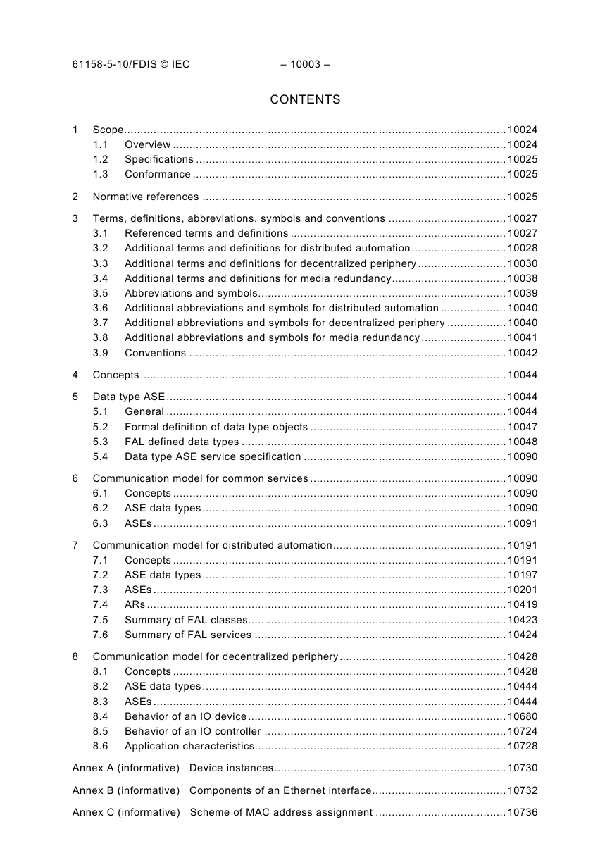
1 Scope
1.1 Overview
1.2 Specifications
1.3 Conformance
2 Normative references
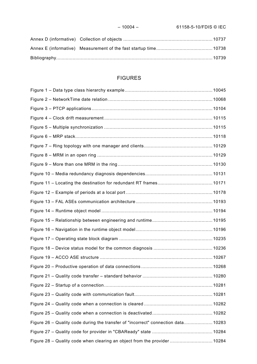
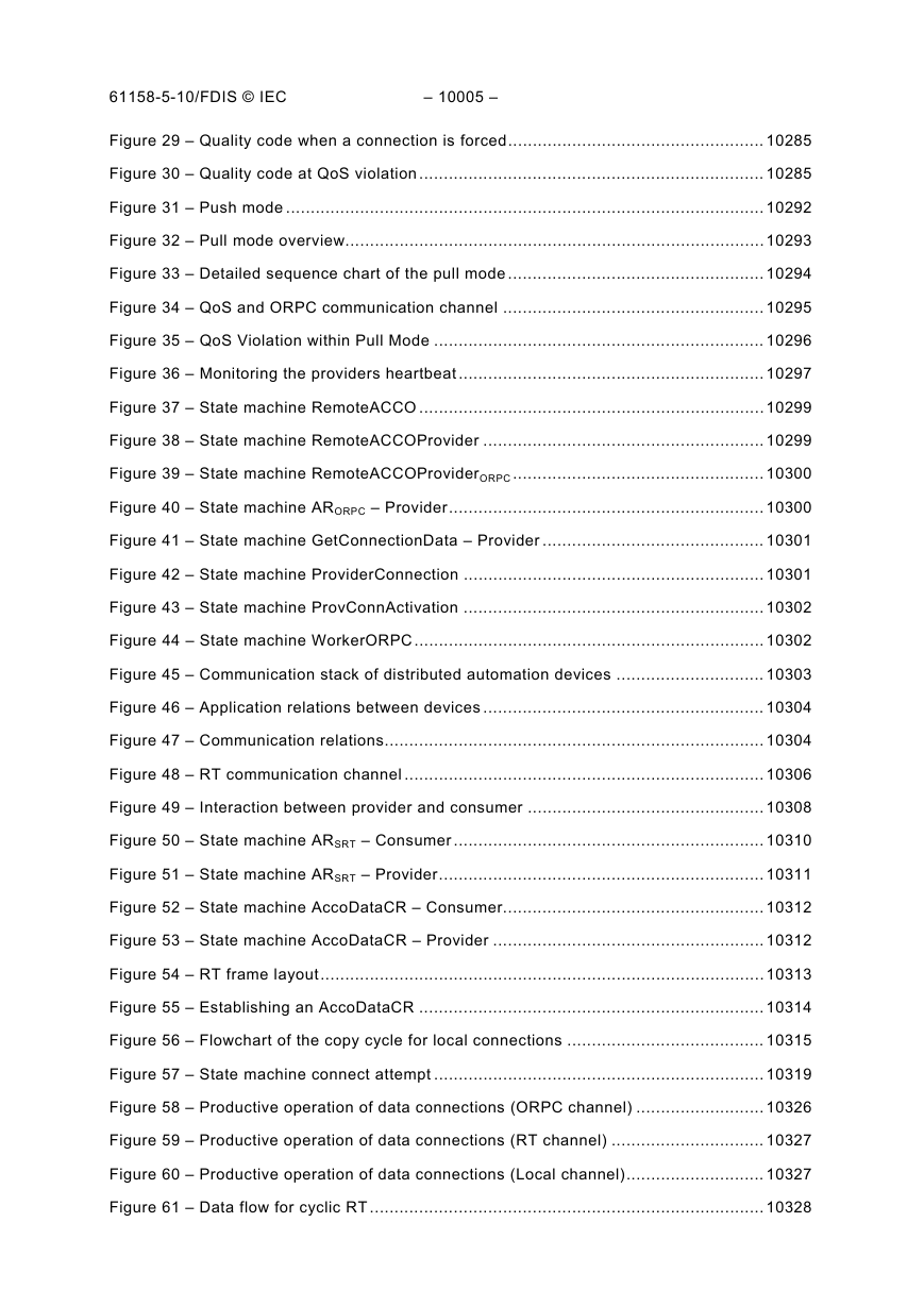
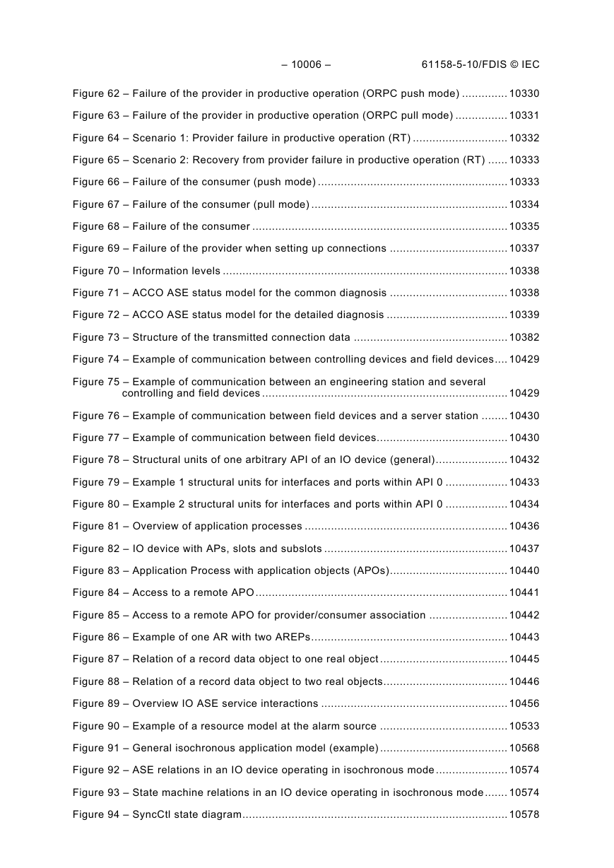
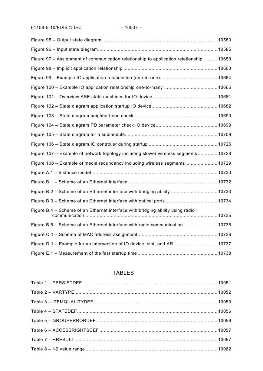
3 Terms, definitions, abbreviations, symbols and conventions
3.1 Referenced terms and definitions
3.1.1 ISO/IEC 7498-1 terms
3.1.2 ISO/IEC 8822 terms
3.1.3 ISO/IEC 9545 terms
3.1.4 ISO/IEC 8824-1 terms
3.2 Additional terms and definitions for distributed automation
3.3 Additional terms and definitions for decentralized periphery
3.4 Additional terms and definitions for media redundancy
3.5 Abbreviations and symbols
3.6 Additional abbreviations and symbols for distributed automation
3.7 Additional abbreviations and symbols for decentralized periphery
3.8 Additional abbreviations and symbols for media redundancy
3.9 Conventions
3.9.1 Overview
3.9.2 General conventions
3.9.3 Conventions for class definitions
3.9.4 Conventions for service definitions
3.9.4.1 General
3.9.4.2 Service parameters
3.9.4.3 Service procedures
4 Concepts
5 Data type ASE
5.1 General
5.1.1 Overview
5.1.2 Basic type overview
5.1.3 Fixed length type overview
5.1.4 Constructed type overview
5.1.4.1 Strings
5.1.4.2 Arrays
5.1.4.3 Structures
5.1.4.4 Nesting level
5.1.5 Specification of user defined data types
5.1.6 Transfer of user data
5.2 Formal definition of data type objects
5.2.1 Data type class
5.2.1.1 Template
5.2.1.2 Attributes
5.3 FAL defined data types
5.3.1 Fixed length types
5.3.1.1 Boolean types
5.3.1.1.1 Boolean
5.3.1.1.2 VARIANT_BOOL
5.3.1.2 Bitstring types
5.3.1.3 Currency types
5.3.1.4 Date types
5.3.1.4.1 date
5.3.1.4.2 Date
5.3.1.4.3 TimeOfDay
5.3.1.4.4 TimeOfDay with date indication
5.3.1.4.5 TimeOfDay without date indication
5.3.1.4.6 TimeDifference
5.3.1.4.7 TimeDifference with date indication
5.3.1.4.8 TimeDifference without date indication
5.3.1.5 Enumerated types
5.3.1.5.1 PERSISTDEF
5.3.1.5.2 VARTYPE
5.3.1.5.3 ITEMQUALITYDEF
5.3.1.5.4 STATEDEF
5.3.1.5.5 GROUPERRORDEF
5.3.1.5.6 ACCESSRIGHTSDEF
5.3.1.6 Handle types
5.3.1.6.1 HRESULT
5.3.1.7 Numeric types
5.3.1.7.1 Floating point types
5.3.1.7.1.1 float
5.3.1.7.1.2 Float32
5.3.1.7.1.3 double
5.3.1.7.1.4 Float64
5.3.1.7.2 Integer types
5.3.1.7.2.1 char
5.3.1.7.2.2 Integer8
5.3.1.7.2.3 short
5.3.1.7.2.4 Integer16
5.3.1.7.2.5 long
5.3.1.7.2.6 Integer32
5.3.1.7.2.7 Integer64
5.3.1.7.3 Unsigned types
5.3.1.7.3.1 unsigned char
5.3.1.7.3.2 Unsigned8
5.3.1.7.3.3 unsigned short
5.3.1.7.3.4 Unsigned16
5.3.1.7.3.5 unsigned long
5.3.1.7.3.6 Unsigned32
5.3.1.7.3.7 Unsigned64
5.3.1.7.3.8 Normalised value N2
5.3.1.7.3.9 Normalised value N4
5.3.1.7.3.10 Variable normalised X2
5.3.1.7.3.11 Variable normalised X4
5.3.1.7.3.12 Unipolar2.16
5.3.1.7.3.13 Fixed point value E2
5.3.1.7.3.14 Fixed point value C4
5.3.1.7.3.15 Bit sequence V2
5.3.1.7.3.16 Nibble L2
5.3.1.8 OctetString character types
5.3.1.8.1 UUID
5.3.1.9 Pointer types
5.3.1.9.1 Interface Pointer
5.3.1.9.2 LPWSTR
5.3.1.10 Time types
5.3.1.10.1 NetworkTime
5.3.1.10.2 NetworkTimeDifference
5.3.1.10.3 Time constant T2
5.3.1.10.4 Time constant T4
5.3.1.10.5 Time constant D2
5.3.1.10.6 Time constant R2
5.3.1.11 VisibleString character types
5.3.2 String types
5.3.2.1 OctetString
5.3.2.2 VisibleString
5.3.2.3 UNICODEString
5.3.3 Structure types
5.3.3.1 ADDCONNECTIONIN
5.3.3.2 ADDCONNECTIONOUT
5.3.3.3 BSTR
5.3.3.4 CONNECTIN
5.3.3.5 CONNECTIN2
5.3.3.6 CONNECTINCR
5.3.3.7 CONNECTINSRT
5.3.3.8 CONNECTOUT
5.3.3.9 CONNECTOUTCR
5.3.3.10 DIAGCONSCONNOUT
5.3.3.11 DISPPARAMS
5.3.3.12 EXCEPINFO
5.3.3.13 FILETIME
5.3.3.14 GETIDOUT
5.3.3.15 GETCONNECTIONOUT
5.3.3.16 GETCONSCONNOUT
5.3.3.17 GETPROVCONNOUT
5.3.3.18 MACAddr
5.3.3.19 OctetString2+Unsigned8
5.3.3.20 Float32+Unsigned8
5.3.3.21 Unsigned8+Unsigned8
5.3.3.22 READITEMOUT
5.3.3.23 SAFEARRAY
5.3.3.24 VARIANT
5.3.3.25 WRITEITEMIN
5.3.3.26 WRITEITEMQCDIN
5.3.3.27 Unsigned16_S
5.3.3.28 Integer16_S
5.3.3.29 Unsigned8_S
5.3.3.30 OctetString_S
5.3.3.31 F message trailer with 4 octets
5.3.3.32 F message trailer with 5 octets
5.4 Data type ASE service specification
6 Communication model for common services
6.1 Concepts
6.2 ASE data types
6.3 ASEs
6.3.1 Discovery and basic configuration ASE
6.3.1.1 Overview
6.3.1.2 DCP class specification
6.3.1.2.1 General
6.3.1.2.2 Template
6.3.1.2.3 Attributes
6.3.1.3 DCP service specification
6.3.1.3.1 Get
6.3.1.3.2 Set
6.3.1.3.3 Identify
6.3.1.3.4 Hello
6.3.2 Precision time control ASE
6.3.2.1 Concepts
6.3.2.2 PTCP class specification
6.3.2.2.1 Template
6.3.2.2.2 Attributes
6.3.2.3 PTCP service specification
6.3.2.3.1 Start bridge
6.3.2.3.2 Start slave
6.3.2.3.3 Start master
6.3.2.3.4 Stop bridge
6.3.2.3.5 Stop slave
6.3.2.3.6 Stop master
6.3.2.3.7 Sync state change
6.3.2.3.8 PTCP behavior
6.3.2.3.8.1 Synchronization
6.3.2.3.8.2 Rate control compensation
6.3.2.3.8.3 Multiple synchronization
6.3.2.3.8.4 Best master algorithm (BMA)
6.3.2.4 Media Redundancy support for synchronization with PTCP
6.3.2.5 Invocation of the PTCP object
6.3.3 Media redundancy ASE
6.3.3.1 Overview
6.3.3.2 Media redundancy class specification
6.3.3.2.1 General
6.3.3.2.2 Template
6.3.3.2.3 Attributes
6.3.3.3 Media redundancy service specification
6.3.3.3.1 Start MRM
6.3.3.3.2 Stop MRM
6.3.3.3.3 Redundancy State Change
6.3.3.3.4 Start MRC
6.3.3.3.5 Stop MRC
6.3.3.3.6 Neighborhood changed
6.3.3.4 Media redundancy behavior
6.3.3.4.1 Ring ports
6.3.3.4.2 Media redundancy manager (MRM)
6.3.3.4.3 Media redundancy client (MRC)
6.3.3.4.4 Redundancy domain
6.3.3.4.5 Multiple MRM in a single ring (option)
6.3.3.4.6 RT media redundancy (option)
6.3.3.5 Usage with diagnosis and alarms
6.3.3.5.1 Media redundancy diagnosis dependencies
6.3.3.6 MRP parameters
6.3.3.6.1 Ring port parameters
6.3.3.6.2 Ring Topology parameters
6.3.3.6.3 MRM and MRC parameters
6.3.4 Real-time cyclic ASE
6.3.4.1 Overview
6.3.4.2 RTC class specification
6.3.4.2.1 General
6.3.4.2.2 Template
6.3.4.2.3 Attributes
6.3.4.3 RTC service specification
6.3.4.3.1 Set Prov Data
6.3.4.3.2 Set Prov Status
6.3.4.3.3 PPM Activate
6.3.4.3.4 Close
6.3.4.3.5 Start
6.3.4.3.6 Error
6.3.4.3.7 Get Cons Data
6.3.4.3.8 Get cons status
6.3.4.3.9 Set RedRole
6.3.4.3.10 CPM activate
6.3.5 Real-time acyclic ASE
6.3.5.1 Overview
6.3.5.2 RTA class specification
6.3.5.2.1 General
6.3.5.2.2 Template
6.3.5.2.3 Attributes
6.3.5.3 RTA service specification
6.3.5.3.1 APMS Activate
6.3.5.3.2 APMR Activate
6.3.5.3.3 APMS A Data
6.3.5.3.4 APMR A Data
6.3.5.3.5 APMR Ack
6.3.5.3.6 APMS error
6.3.5.3.7 APMR Error
6.3.5.3.8 APMS_Close
6.3.5.3.9 APMR_Close
6.3.6 Remote procedure call ASE
6.3.6.1 Overview
6.3.6.2 RPC class specification
6.3.6.2.1 Template
6.3.6.2.2 Attributes
6.3.6.3 RPC service specification
6.3.6.3.1 Connect
6.3.6.3.2 Release
6.3.6.3.3 Read
6.3.6.3.4 Write
6.3.6.3.5 Control
6.3.7 Link layer discovery ASE
6.3.7.1 Overview
6.3.7.2 IEEE 802.1AB class specification
6.3.7.2.1 Template
6.3.7.2.2 Attributes
6.3.7.2.3 Invocation of the IEEE 802.1AB object
6.3.7.3 IEEE 802.1AB service specification
6.3.7.3.1 Remote systems data change
6.3.7.3.2 Placeholder
6.3.8 MAC bridges ASE
6.3.8.1 Overview
6.3.8.2 IEEE 802.1D class specification
6.3.8.2.1 General
6.3.8.2.2 Template
6.3.8.2.3 Attributes
6.3.8.3 IEEE 802.1D service specification
6.3.8.3.1 Port state change
6.3.8.3.2 Set port state
6.3.8.3.3 Flush filtering data base
6.3.8.3.4 IFW IRT Schedule Add
6.3.8.3.5 IFW IRT Schedule Remove
6.3.8.3.6 IFW Schedule
6.3.8.4 Invocation of the IEEE 802.1D object
6.3.9 Virtual bridged LAN ASE
6.3.9.1 Overview
6.3.9.2 IEEE 802.1Q class specification
6.3.9.2.1 Template
6.3.9.2.2 Attributes
6.3.9.2.3 Invocation of the IEEE 802.1Q object
6.3.9.3 IEEE 802.1Q service specification
6.3.10 Medium access ASE
6.3.10.1 Overview
6.3.10.2 IEEE 802.3 class specification
6.3.10.2.1 General
6.3.10.2.2 Template
6.3.10.2.3 Attributes
6.3.10.3 IEEE 802.3 service specification
6.3.10.3.1 MAU type Change
6.3.10.3.2 Set MAU type
6.3.10.4 Invocation of the IEEE 802.3 object
6.3.11 IP suite ASE
6.3.11.1 Overview
6.3.11.2 IP suite class specification
6.3.11.2.1 General
6.3.11.2.2 Template
6.3.11.2.3 Attributes
6.3.11.3 IP suite service specification
6.3.11.3.1 Set ARP Cache
6.3.12 Domain name system ASE
6.3.12.1 Overview
6.3.12.2 DNS class specification
6.3.12.2.1 General
6.3.12.2.2 Template
6.3.12.2.3 Attributes
6.3.12.3 DNS service specification
6.3.13 Dynamic host configuration ASE
6.3.13.1 Overview
6.3.13.2 DHCP class specification
6.3.13.2.1 General
6.3.13.2.2 Template
6.3.13.2.3 Attributes
6.3.13.3 DHCP service specification
6.3.14 Simple network management ASE
6.3.14.1 Overview
6.3.14.2 SNMP class specification
6.3.14.2.1 General
6.3.14.2.2 Template
6.3.14.2.3 Attributes
6.3.14.3 SNMP service specification
6.3.15 Common DL mapping ASE
6.3.15.1 Overview
6.3.15.2 DL Mapping class specification
6.3.15.2.1 General
6.3.15.2.2 Template
6.3.15.2.3 Attributes
6.3.15.3 DL Mapping service specification
6.3.15.3.1 IRT Schedule Add
6.3.15.3.2 IRT Schedule Remove
6.3.15.3.3 Schedule
6.3.15.3.4 N Data
6.3.15.3.5 A Data
6.3.15.3.6 C Data
7 Communication model for distributed automation
7.1 Concepts
7.1.1 Overview
7.1.2 Objectives of the FAL AE
7.1.3 Devices types
7.1.4 FAL ASEs
7.1.5 Runtime object model
7.1.6 Navigation in the object model
7.1.7 Online/offline comparison
7.2 ASE data types
7.2.1 Supported data types
7.2.2 Connectable data types
7.2.3 Extended type description
7.2.4 Definitions for identifiers
7.2.4.1 Character set type 1
7.2.4.2 Character set type 2
7.2.4.3 Common definitions
7.2.4.4 Usage of character sets
7.3 ASEs
7.3.1 Object Management ASE
7.3.1.1 Overview
7.3.1.2 Class specification
7.3.1.2.1 Template
7.3.1.2.2 Attributes
7.3.1.3 Service specification
7.3.1.3.1 Interface Unknown
7.3.1.3.1.1 QueryInterface
7.3.1.3.1.2 AddRef
7.3.1.3.1.3 Release
7.3.1.3.2 Interface Dispatch
7.3.1.3.2.1 GetTypeInfoCount
7.3.1.3.2.2 GetTypeInfo
7.3.1.3.2.3 GetIDsOfNames
7.3.1.3.2.4 Invoke
7.3.2 AP ASE
7.3.2.1 Physical device
7.3.2.1.1 Overview
7.3.2.1.2 Physical Device class specification
7.3.2.1.2.1 Template
7.3.2.1.2.2 Attributes
7.3.2.1.3 Physical device behavior
7.3.2.1.3.1 Overview
7.3.2.1.3.2 Online/offline comparison of the LDev objects
7.3.2.1.4 Physical device service specification
7.3.2.1.4.1 Interface physical device
7.3.2.1.4.1.1 get_Producer
7.3.2.1.4.1.2 get_Product
7.3.2.1.4.1.3 get_SerialNo
7.3.2.1.4.1.4 get_ProductionDate
7.3.2.1.4.1.5 Revision
7.3.2.1.4.1.6 get_LogicalDevice
7.3.2.1.4.1.7 Type
7.3.2.1.4.1.8 PROFInetRevision
7.3.2.1.4.1.9 get_PDevStamp
7.3.2.1.4.2 Interface Browse
7.3.2.1.4.2.1 get_Count
7.3.2.1.4.2.2 BrowseItems
7.3.2.1.4.2.3 get_Count2
7.3.2.1.4.2.4 BrowseItems2
7.3.2.1.4.3 Interface Persist
7.3.2.1.4.3.1 Save
7.3.2.1.4.3.2 Save2
7.3.2.2 Logical Device
7.3.2.2.1 Overview
7.3.2.2.2 Logical Device class specification
7.3.2.2.2.1 Template
7.3.2.2.2.2 Attributes
7.3.2.2.3 Logical Device behavior
7.3.2.2.3.1 Operating state
7.3.2.2.3.2 Diagnosis
7.3.2.2.4 Logical Device service specification
7.3.2.2.4.1 Interface logical device
7.3.2.2.4.1.1 get_Name
7.3.2.2.4.1.2 get_Producer
7.3.2.2.4.1.3 get_Product
7.3.2.2.4.1.4 get_SerialNo
7.3.2.2.4.1.5 get_ProductionDate
7.3.2.2.4.1.6 Revision
7.3.2.2.4.1.7 get_ACCO
7.3.2.2.4.1.8 get_RTAuto
7.3.2.2.4.1.9 PROFInetRevision
7.3.2.2.4.1.10 ComponentInfo
7.3.2.2.4.2 Interface State
7.3.2.2.4.2.1 get_State
7.3.2.2.4.2.2 Activate
7.3.2.2.4.2.3 Deactivate
7.3.2.2.4.2.4 Reset
7.3.2.2.4.2.5 AdviseState
7.3.2.2.4.2.6 UnadviseState
7.3.2.2.4.3 Interface Time
7.3.2.2.4.3.1 get_Time
7.3.2.2.4.3.2 put_Time
7.3.2.2.4.4 Interface Browse
7.3.2.2.4.4.1 get_Count
7.3.2.2.4.4.2 BrowseItems
7.3.2.2.4.4.3 get_Count2
7.3.2.2.4.4.4 BrowseItems2
7.3.2.2.4.5 Interface group error
7.3.2.2.4.5.1 GroupError
7.3.2.2.4.5.2 AdviseGroupError
7.3.2.2.4.5.3 UnadviseGroupError
7.3.3 ACCO ASE
7.3.3.1 Overview
7.3.3.2 ACCO class specification
7.3.3.2.1 Template
7.3.3.2.2 Attributes
7.3.3.3 ACCO Behavior
7.3.3.3.1 Interconnecting RT-Auto objects – ACCO
7.3.3.3.2 Architecture
7.3.3.3.3 Short overview
7.3.3.3.3.1 Establishing connections
7.3.3.3.3.2 Productive operation of data connections
7.3.3.3.4 Definitions
7.3.3.3.4.1 Configuration Data Base
7.3.3.3.4.2 Rules for connections
7.3.3.3.4.3 Definition of the identifiers
7.3.3.3.4.3.1 Identifier for an LDev object
7.3.3.3.4.3.2 Identifier for an RT-Auto menber
7.3.3.3.4.3.3 Identifier for a System Member
7.3.3.3.4.3.4 Identifiers for accessing sub elements
7.3.3.3.4.4 Quality of Service (QoS)
7.3.3.3.4.5 Dead band and epsilon value
7.3.3.3.4.6 Version of a connection
7.3.3.3.4.7 Substitute values
7.3.3.3.4.8 Quality code
7.3.3.3.4.8.1 Overview
7.3.3.3.4.8.2 Using quality codes
7.3.3.3.4.8.3 Standard behavior for quality codes
7.3.3.3.4.8.4 Startup of a connection
7.3.3.3.4.8.5 Behavior in case of a communication fault
7.3.3.3.4.8.6 Behavior in case of connection is cleared
7.3.3.3.4.8.7 Behavior in case of connection is deactivated
7.3.3.3.4.8.8 Behavior in case of "incorrect" connection data
7.3.3.3.4.8.9 Behavior in case of the provider in "CBAReady" state
7.3.3.3.4.8.10 Behavior in case of clearing an object from the provider
7.3.3.3.4.8.11 Behavior in case of connection is forced
7.3.3.3.4.8.12 Behavior in case of QoS violation
7.3.3.3.4.8.13 Write access to values via put-services or WriteItem services
7.3.3.3.4.8.14 Component-overlapping quality code
7.3.3.3.4.8.15 Property access and quality code
7.3.3.3.4.9 Operating state
7.3.3.3.4.10 Power-On
7.3.3.3.4.11 Persistence
7.3.3.3.4.12 Online/offline comparison of the connections
7.3.3.3.5 Communication channels
7.3.3.3.5.1 Configuration
7.3.3.3.5.2 ORPC communication channel
7.3.3.3.5.2.1 General
7.3.3.3.5.2.2 Context management
7.3.3.3.5.2.2.1 Overview
7.3.3.3.5.2.2.2 Push mode
7.3.3.3.5.2.2.3 Pull mode
7.3.3.3.5.2.3 QoS
7.3.3.3.5.2.4 QoS violation
7.3.3.3.5.2.5 Connection monitoring
7.3.3.3.5.2.5.1 Connection monitoring by the consumer – Push mode
7.3.3.3.5.2.5.2 Connection monitoring by the consumer – Pull mode
7.3.3.3.5.2.5.3 Connection monitoring by the provider – Push mode
7.3.3.3.5.2.5.4 Connection monitoring by the provider – Pull mode
7.3.3.3.5.2.6 State machines
7.3.3.3.5.2.6.1 State machine RemoteACCO
7.3.3.3.5.2.6.2 State machine RemoteACCOProvider
7.3.3.3.5.2.6.3 State machine RemoteACCOProviderORPC
7.3.3.3.5.2.6.4 State machine ARORPC
7.3.3.3.5.2.6.5 State machine GetConnectionData – Provider
7.3.3.3.5.2.6.6 State machine ProviderConnection
7.3.3.3.5.2.6.7 State machine ProvConnActivation
7.3.3.3.5.2.6.8 State machine WorkerORPC
7.3.3.3.5.3 RT communication channel
7.3.3.3.5.3.1 General
7.3.3.3.5.3.2 Application relations and communication relations
7.3.3.3.5.3.3 Using RT
7.3.3.3.5.3.3.1 RT variants
7.3.3.3.5.3.3.2 Frame ID
7.3.3.3.5.3.3.3 Segmentation
7.3.3.3.5.3.3.4 RT cycle time and QoS value
7.3.3.3.5.3.3.5 QoS violation
7.3.3.3.5.3.3.6 Connection monitoring
7.3.3.3.5.3.3.6.1 Connection monitoring by the consumer
7.3.3.3.5.3.3.6.2 Connection monitoring by the provider
7.3.3.3.5.3.4 State machines
7.3.3.3.5.3.4.1 Remote interactions
7.3.3.3.5.3.4.2 State machine for application relations
7.3.3.3.5.3.4.3 State machine for AccoDataCR
7.3.3.3.5.4 Local communication channel
7.3.3.3.5.4.1 Overview
7.3.3.3.5.4.2 QoS
7.3.3.3.5.4.3 QoS violation
7.3.3.3.5.5 Constant communication channel
7.3.3.3.6 ACCO Management operation
7.3.3.3.6.1 Overview
7.3.3.3.6.1.1 Tasks of the consumer
7.3.3.3.6.1.2 Tasks of the provider
7.3.3.3.6.2 Establishing connections
7.3.3.3.6.2.1 Overview
7.3.3.3.6.2.2 Connections with a constant
7.3.3.3.6.2.3 Negotiating with the provider – common definitions
7.3.3.3.6.2.3.1 General
7.3.3.3.6.2.3.2 Connect attempt
7.3.3.3.6.2.3.3 Signature identity check
7.3.3.3.6.2.3.3.1 Overview
7.3.3.3.6.2.3.3.2 Signature identity check for data connections (Base object version 1)
7.3.3.3.6.2.3.3.3 Signature identity check for data connections (Base object version 2)
7.3.3.3.6.2.4 Negotiating with the provider – ORPC
7.3.3.3.6.2.5 Negotiating with the provider – RT
7.3.3.3.6.2.5.1 General
7.3.3.3.6.2.5.2 Reconfiguration
7.3.3.3.6.2.6 Negotiating with the provider – Local
7.3.3.3.6.2.7 Negotiating with the provider – Constant
7.3.3.3.6.3 Changing connections
7.3.3.3.6.4 Clearing connections
7.3.3.3.6.4.1 General
7.3.3.3.6.4.2 Negotiating with the provider – ORPC
7.3.3.3.6.4.3 Negotiating with the provider – RT
7.3.3.3.6.4.4 Negotiating with the provider – Local
7.3.3.3.6.4.5 Negotiating with the provider – Constant
7.3.3.3.6.5 Activating and deactivating connections
7.3.3.3.6.5.1 General
7.3.3.3.6.5.2 Negotiating with the provider – ORPC
7.3.3.3.6.5.3 Negotiating with the provider – RT
7.3.3.3.6.5.4 Negotiating with the provider – Local
7.3.3.3.6.5.5 Negotiating with the provider – Constant
7.3.3.3.7 Productive operations of connections
7.3.3.3.7.1 Overview
7.3.3.3.7.2 Productive operation for data connections
7.3.3.3.7.2.1 ORPC channel
7.3.3.3.7.2.2 RT channel
7.3.3.3.7.2.3 Local channel
7.3.3.3.7.3 Productive operation for the RT communication channel
7.3.3.3.7.4 Fault scenarios
7.3.3.3.7.4.1 Overview
7.3.3.3.7.4.2 Time intervals
7.3.3.3.7.4.3 Packet duplication
7.3.3.3.7.4.4 Packet loss
7.3.3.3.7.4.5 Garbled data
7.3.3.3.7.4.6 Sequence switching
7.3.3.3.7.4.7 Recycling frames
7.3.3.3.7.4.8 Failure of the provider in productive operation
7.3.3.3.7.4.8.1 ORPC communication channel
7.3.3.3.7.4.8.2 RT communication channel
7.3.3.3.7.4.9 Failure of the consumer in productive operation
7.3.3.3.7.4.9.1 ORPC communication channel
7.3.3.3.7.4.9.2 RT communication channel
7.3.3.3.7.4.10 Unilateral communication failure recognition during productive operation
7.3.3.3.7.4.10.1 ORPC communication channel
7.3.3.3.7.4.10.2 RT communication channel
7.3.3.3.7.4.11 Failure of the provider during negotiation
7.3.3.3.7.4.12 Transmission of garbled data
7.3.3.3.8 Connection diagnosis
7.3.3.3.9 Synchronous Read / Write
7.3.3.3.9.1 Overview
7.3.3.3.9.2 Synchronous access
7.3.3.4 ACCO Service specification
7.3.3.4.1 Interface ACCO Management
7.3.3.4.1.1 AddConnections
7.3.3.4.1.2 RemoveConnections
7.3.3.4.1.3 ClearConnections
7.3.3.4.1.4 SetActivationState
7.3.3.4.1.5 GetInfo
7.3.3.4.1.6 GetIDs
7.3.3.4.1.7 GetConnections
7.3.3.4.1.8 ReviseQoS
7.3.3.4.1.9 get_PingFactor
7.3.3.4.1.10 put_PingFactor
7.3.3.4.1.11 get_CDBCookie
7.3.3.4.1.12 GetConsIDs
7.3.3.4.1.13 GetConsConnections
7.3.3.4.1.14 DiagConsConnections
7.3.3.4.1.15 GetProvIDs
7.3.3.4.1.16 GetProvConnections
7.3.3.4.1.17 GetDiagnosis
7.3.3.4.2 Interface ACCO Server
7.3.3.4.2.1 Connect
7.3.3.4.2.2 Disconnect
7.3.3.4.2.3 DisconnectMe
7.3.3.4.2.4 SetActivation
7.3.3.4.2.5 Ping
7.3.3.4.2.6 Connect2
7.3.3.4.2.7 GetConnectionData
7.3.3.4.3 Interface ACCO Callback
7.3.3.4.3.1 OnDataChanged
7.3.3.4.3.2 Gnip
7.3.3.4.4 Interface ACCO Sync
7.3.3.4.4.1 ReadItems
7.3.3.4.4.2 WriteItems
7.3.3.4.4.3 WriteItemsQCD
7.3.3.4.5 Interface Group Error
7.3.3.4.5.1 GroupError
7.3.3.4.5.2 AdviseGroupError
7.3.3.4.5.3 UnadviseGroupError
7.3.3.4.6 Interface ACCO Server SRT
7.3.3.4.6.1 ConnectCR
7.3.3.4.6.2 DisconnectCR
7.3.3.4.6.3 Connect
7.3.3.4.6.4 Disconnect
7.3.3.4.6.5 DisconnectMe
7.3.3.4.6.6 SetActivation
7.3.4 RT-Auto ASE
7.3.4.1 Overview
7.3.4.2 RT-Auto class specification
7.3.4.2.1 Template
7.3.4.2.2 Attributes
7.3.4.3 RT-Auto behavior
7.3.4.3.1 General
7.3.4.3.2 Interconnecting RT-Auto objects
7.3.4.3.3 Property access
7.3.4.4 RT-Auto service specification
7.3.4.4.1 Interface RT-Auto
7.3.4.4.1.1 get_Name
7.3.4.4.1.2 Revision
7.3.4.4.1.3 ComponentInfo
7.3.4.4.2 Interface Browse
7.3.4.4.2.1 get_Count
7.3.4.4.2.2 BrowseItems
7.3.4.4.2.3 get_Count2
7.3.4.4.2.4 BrowseItems2
7.3.4.4.3 Interface system properties
7.3.4.4.3.1 get_StateCollection
7.3.4.4.3.2 get_StampCollection
7.4 ARs
7.4.1 Overview
7.4.2 ORPC AR class specification
7.4.2.1 Formal definition
7.4.2.2 Attributes
7.4.3 ORPC AR service specification
7.4.3.1 CoCreateInstance
7.4.3.2 CoDisconnectObject
7.4.3.3 Call
7.5 Summary of FAL classes
7.6 Summary of FAL services
8 Communication model for decentralized periphery
8.1 Concepts
8.1.1 User requirements
8.1.2 Features
8.1.3 Associations
8.1.4 Device types
8.1.4.1 General
8.1.4.2 IO controller
8.1.4.3 IO supervisor
8.1.4.4 IO parameter server
8.1.4.5 IO device
8.1.4.5.1 General
8.1.4.5.2 Slot
8.1.4.5.3 Subslot
8.1.4.5.4 Channel
8.1.5 Instance model and device addresses
8.1.6 Application process
8.1.6.1 Overview
8.1.6.2 Application service element
8.1.6.3 Application objects
8.1.7 Application relationship
8.1.7.1 General
8.1.7.2 Application relationship endpoint
8.1.7.3 Overview of application relationships
8.2 ASE data types
8.3 ASEs
8.3.1 Record data ASE
8.3.1.1 Overview
8.3.1.2 Record data class specification
8.3.1.2.1 Template
8.3.1.2.2 Attributes
8.3.1.2.3 Invocation of the Record Data object
8.3.1.3 Record data service specification
8.3.1.3.1 Read
8.3.1.3.2 Read Query
8.3.1.3.3 Write
8.3.2 IO Data ASE
8.3.2.1 Overview
8.3.2.2 IO Data class specification
8.3.2.2.1 Input Data class specification
8.3.2.2.1.1 Template
8.3.2.2.1.2 Attributes
8.3.2.2.1.3 Invocation of the Input Data object
8.3.2.2.2 Output data class specification
8.3.2.2.2.1 Template
8.3.2.2.2.2 Attributes
8.3.2.2.2.3 Invocation of the Output Data object
8.3.2.3 IO Data service specification
8.3.2.3.1 Set input
8.3.2.3.2 Set input IOCS
8.3.2.3.3 Get Input
8.3.2.3.4 Get Input IOCS
8.3.2.3.5 New Input
8.3.2.3.6 Set Input APDU Data Status
8.3.2.3.7 New Input APDU Data Status
8.3.2.3.8 Read input data
8.3.2.3.9 Set Output
8.3.2.3.10 Set Output IOCS
8.3.2.3.11 Get Output
8.3.2.3.12 Get Output IOCS
8.3.2.3.13 New Output
8.3.2.3.14 Set Output APDU Data Status
8.3.2.3.15 New Output APDU Data Status
8.3.2.3.16 Read Output Data
8.3.2.3.17 Read Output Substitute Data
8.3.2.3.18 Write Output Substitute Data
8.3.2.4 Behavior of IO Data objects
8.3.2.4.1 General behavior of the Input Data object
8.3.2.4.2 General behavior of the Output Data object
8.3.3 Logbook Data ASE
8.3.3.1 Overview
8.3.3.2 Logbook Data class specification
8.3.3.2.1 Template
8.3.3.2.2 Attributes
8.3.3.3 Logbook Data service specification
8.3.3.3.1 Read logbook
8.3.3.3.2 Logbook Event
8.3.4 Diagnosis ASE
8.3.4.1 Overview
8.3.4.2 Diagnosis class specification
8.3.4.2.1 Template
8.3.4.2.2 Attributes
8.3.4.2.3 Invocation of the Diagnosis object
8.3.4.3 Diagnosis service specification
8.3.4.3.1 Read Device Diagnosis
8.3.4.3.2 Diagnosis Item
8.3.4.3.3 Diagnosis Event
8.3.4.3.4 Behavior of Diagnosis objects
8.3.4.3.5 General behavior of the Diagnosis object
8.3.4.3.6 Behavior Diagnosis entry
8.3.4.3.7 Behavior maintenance required entry
8.3.4.3.8 Behavior maintenance demanded entry
8.3.4.3.9 Behavior qualified entry
8.3.4.3.10 Optimization for Diagnosis objects
8.3.4.3.10.1 Subslot Number level
8.3.4.3.10.2 Channel Error type level
8.3.5 Alarm ASE
8.3.5.1 Overview
8.3.5.2 Alarm class specification
8.3.5.2.1 Template
8.3.5.2.2 Attributes
8.3.5.2.3 Invocation of the Alarm object
8.3.5.3 Alarm service specification
8.3.5.3.1 Alarm Notification
8.3.5.3.2 Alarm Ack
8.3.5.4 Behavior of Alarm objects
8.3.5.4.1 General behavior of the alarm sink
8.3.5.4.2 General behavior of the alarm source
8.3.5.4.3 Behavior for diagnosis changes
8.3.6 Context ASE
8.3.6.1 Overview
8.3.6.2 Context class specification
8.3.6.2.1 Template
8.3.6.2.2 Attributes
8.3.6.2.3 Invocation of the Context object
8.3.6.3 Context service specification
8.3.6.3.1 Connect
8.3.6.3.2 Connect Device Access
8.3.6.3.3 Release
8.3.6.3.4 Abort
8.3.6.3.5 End Of Parameter
8.3.6.3.6 Application Ready
8.3.6.3.7 Ready For Companion
8.3.6.3.8 Read Expected Identification
8.3.6.3.9 Read Real Identification
8.3.6.3.10 Read Identification Difference
8.3.6.4 Behavior of the Context object
8.3.6.5 Behavior of the attribute Submodule State
8.3.7 Isochronous Mode Application ASE
8.3.7.1 Overview
8.3.7.2 Isochronous Mode Application class specification
8.3.7.2.1 Template
8.3.7.2.2 Attributes
8.3.7.3 Isochronous Mode Application service specification
8.3.7.3.1 Write IsoM Data
8.3.7.3.2 Read IsoM Data
8.3.7.3.3 SYNCH Event
8.3.7.4 Behavior of Isochronous Mode Application objects
8.3.7.4.1 Overview of relations to other ASE objects
8.3.7.4.2 Basic behavior of input and output data in the isochronous mode
8.3.7.4.3 State machine description for isochronous mode
8.3.7.4.3.1 General
8.3.7.4.3.2 Primitive definitions
8.3.7.4.3.2.1 Primitives exchanged between the AL and the SyncCtl state machine
8.3.7.4.3.2.2 Primitive exchanged between the SyncCtl state machine and the user
8.3.7.4.3.2.3 Primitive exchanged between the Input state machine and the user
8.3.7.4.3.2.4 Primitive exchanged between the output state machine and the user
8.3.7.4.3.2.5 Primitives exchanged between the Output state machine and the SyncCtl state machine
8.3.7.4.3.2.6 Primitives exchanged between the Input state machine and the SyncCtl state machine
8.3.7.4.3.2.7 Primitives exchanged between the AL and the Output state machine
8.3.7.4.3.2.8 Primitives exchanged between the Input state machine and the AL
8.3.7.4.3.3 SyncCtl state diagram
8.3.7.4.3.4 SyncCtl state table
8.3.7.4.3.5 Output state diagram
8.3.7.4.3.6 Output state table
8.3.7.4.3.7 Input state diagram
8.3.7.4.3.8 Input state table
8.3.8 Physical Device Management ASE
8.3.8.1 Overview
8.3.8.2 Physical Device Management class specification
8.3.8.2.1 General
8.3.8.2.2 Physical Device Management class specification
8.3.8.2.2.1 Template
8.3.8.2.2.2 Attributes
8.3.8.3 Physical Device Management service specification
8.3.8.3.1 Write Expected Port Data
8.3.8.3.2 Write Adjusted Port Data
8.3.8.3.3 Read Real Port Data
8.3.8.3.4 Read Expected Port Data
8.3.8.3.5 Read Adjusted Port Data
8.3.8.3.6 Write IR Data
8.3.8.3.7 Read IR Data
8.3.8.3.8 Write Sync Data
8.3.8.3.9 Read Real Sync Data
8.3.8.3.10 Read Expected Sync Data
8.3.8.3.11 Read PDev Data
8.3.8.3.12 Sync State Info
8.3.8.3.13 Write Adjusted Fiber Optic Data
8.3.8.3.14 Read real fiber optic data
8.3.8.3.15 Write MRP Interface Data
8.3.8.3.16 Read MRP Interface Data
8.3.8.3.17 Write MRP Port Data
8.3.8.3.18 Read MRP Port Data
8.3.8.3.19 Write FSU Data
8.3.8.3.20 Read FSU Data
8.3.9 Network Continuous Time ASE
8.3.9.1 Overview
8.3.9.2 Network Continuous Time class specification
8.3.9.2.1 Template
8.3.9.2.2 Attributes
8.3.9.2.3 Invocation of the Network Continuous Time object
8.3.9.3 Network Continuous Time service specification
8.3.9.3.1 Set time
8.3.9.3.2 Placeholder
8.3.10 AR ASE
8.3.10.1 Overview
8.3.10.1.1 General
8.3.10.1.2 Communication relationship
8.3.10.1.2.1 General
8.3.10.1.2.2 Communication relationship endpoint
8.3.10.1.2.3 Buffer and queues
8.3.10.1.2.4 Communication relationship endpoint roles
8.3.10.1.2.5 Overview of communication relationships
8.3.10.2 Application relationships
8.3.10.2.1 Implicit application relationship
8.3.10.2.2 IO application relationship
8.3.10.2.3 Supervisor application relationship
8.3.10.3 ARL class specification
8.3.10.3.1 Template
8.3.10.3.2 Attributes
8.3.10.4 CRL class specification
8.3.10.4.1 Template
8.3.10.4.2 Attributes
8.3.10.4.3 Invocation of CRL object
8.3.10.5 AR service specification
8.3.10.5.1 Read AR Data
8.3.10.5.2 Placeholder
8.4 Behavior of an IO device
8.4.1 Overview
8.4.2 Startup of an IO device
8.4.3 Physical Device parameter check
8.4.3.1 Remote system data
8.4.3.2 Local system data
8.4.3.3 Optical system data
8.4.4 Diagnosis and problem indicator
8.4.5 User alarms
8.4.6 Behavior in case of configuration change
8.4.6.1 General
8.4.6.2 State behavior of submodules
8.4.7 Behavior for PTCP within IO devices
8.4.7.1 Diagnosis and Alarms
8.4.7.2 Sync error dependencies
8.4.7.3 State machine description
8.4.7.4 State table
8.4.7.5 Functions
8.5 Behavior of an IO controller
8.5.1 Overview
8.5.2 Behavior of an IO controller during startup
8.6 Application characteristics
8.6.1 Device ident number
8.6.2 Network topology
Bibliography


 2023年江西萍乡中考道德与法治真题及答案.doc
 2012年重庆南川中考生物真题及答案.doc
 2013年江西师范大学地理学综合及文艺理论基础考研真题.doc
 2020年四川甘孜小升初语文真题及答案I卷.doc
 2020年注册岩土工程师专业基础考试真题及答案.doc
 2023-2024学年福建省厦门市九年级上学期数学月考试题及答案.doc
 2021-2022学年辽宁省沈阳市大东区九年级上学期语文期末试题及答案.doc
 2022-2023学年北京东城区初三第一学期物理期末试卷及答案.doc
 2018上半年江西教师资格初中地理学科知识与教学能力真题及答案.doc
 2012年河北国家公务员申论考试真题及答案-省级.doc
 2020-2021学年江苏省扬州市江都区邵樊片九年级上学期数学第一次质量检测试题及答案.doc
 2022下半年黑龙江教师资格证中学综合素质真题及答案.doc