logo资料库

ADLINK 6U CompactPCI单板计算机cPCI-6841 cPCI-6842.pdf

第1页 / 共155页
第2页 / 共155页
第3页 / 共155页
第4页 / 共155页
第5页 / 共155页
第6页 / 共155页
第7页 / 共155页
第8页 / 共155页
资料共155页,剩余部分请下载后查看
Table of Contents
List of Tables
List of Figures
1 Introduction
1.1 Main Functions
CPU Support
CompactPCI Bus Interface
PCI Mezzanine Card (PMC) Interface
IDE and CompactFlash Interfaces
Gigabit Ethernet Ports
Universal Serial Bus (USB)
Serial I/O
Keyboard/Mouse Controller
FDD Interface
Watchdog Timer
Hardware Monitoring
Operating System Support
1.2 Features
1.3 Product List
1.4 Specifications
cPCI-6841 SBC Specifications
I/O Connectivity
1.5 Unpacking Checklist
2 Jumpers and Connectors
2.1 cPCI-6841 Series Mechanical Drawings
2.2 cPCI-6841 Series Pin Assignments
USB Connectors
VGA Connector
Ethernet (RJ-45) Connector
PS2 Connector
RS-232 Serial Port Connector
DVI Connector
CompactFlash Connector
Floppy Connector
IDE Connector
General Purpose LED definitions
PMC Connector Pin Assignments (JN1, JN2)
CompactPCI J1 Pin Assignment
CompactPCI J2 Pin Assignment
CompactPCI J3 Pin Assignment (optional)
2.3 cPCI-6841 Series Switch and Jumper Settings
SW1: Reset Button
JP1: CF Master or Slave Selection
JP3: PMC VIO Selection
3 Getting Started
3.1 CPU and Heatsink
CPU Installation
Heatsink Installation
3.2 Memory Module Installation
3.3 PCI Mezzanine Card (PMC) Installation (cPCI-6841 only)
3.4 HDD Installation on Main Board
3.5 CF Installation (cPCI-6841 only)
3.6 Main Board Installation
4 Windows Driver Installation
4.1 Chipset Drivers Installation
4.2 VGA Driver Installation
4.3 LAN Driver Installation
5 Utilities
5.1 Watchdog Timer
5.2 Using the Watchdog in an Application
5.3 Intel Preboot Execution Environment (PXE)
Appendix
Serial Console User’s Guide
1. Introduction
2. Equipment Needed
3. Seting up the Server
4. How to Use the Serial Console
Warranty Policy

cPCI-6842_Manual_1.pdf
Table of Contents
List of Tables
List of Figures
1 Introduction
1.1 Main Functions
CPU Support
CompactPCI Bus Interface
PCI Mezzanine Card (PMC) Interface
IDE and CompactFlash Interfaces
Gigabit Ethernet Ports
Universal Serial Bus (USB)
Serial I/O
IEEE-1284 Parallel Port/Printer Interface
Keyboard/Mouse Controller
FDD Interface
Compact Flash
Watchdog Timer
Hardware Monitoring
Operating System Support
1.2 Features
1.3 Product List
1.4 Specifications
cPCI-6842V SBC Specifications
I/O Connectivity
1.5 Unpacking Checklist
2 Jumpers and Connectors
2.1 cPCI-6842 Series Mechanical Drawings
2.2 cPCI-6842 Series Pin Assignments
USB Connectors
VGA Connector
Ethernet (RJ-45) Connector
PS2 Connector
RS-232 Serial Port Connector
Parallel Port Connector
DVI Connector
CompactFlash Connector
Floppy Connector
IDE Connector
General Purpose LED definitions
PMC Connector Pin Assignments (JN1, JN2)
CompactPCI J1 Pin Assignment
CompactPCI J2 Pin Assignment
CompactPCI J3 Pin Assignment (optional)
2.3 cPCI-6842 Series Switch and Jumper Settings
SW1: Reset Button
JP2: PMC VIO Selection
3 Getting Started
3.1 CPU and Heatsink
CPU Installation
Heatsink Installation
3.2 Memory Module Installation
3.3 HDD Installation on Main Board
3.4 PCI Mezzanine Card (PMC) Installation
3.5 CF Installation (cPCI-6842 only)
3.6 Main Board Installation
4 Windows Driver Installation
4.1 Chipset Drivers Installation
4.2 VGA Driver Installation
4.3 LAN Driver Installation
5 Utilities
5.1 Watchdog Timer
5.2 Using the Watchdog in an Application
5.3 Intel Preboot Execution Environment (PXE)
Appendix
Serial Console User’s Guide
1. Introduction
2. Equipment Needed
3. Seting up the Server
4. How to Use the Serial Console
Warranty Policy

cPCI-6841 Series 6U CompactPCI Pentium M Single Board Computers User’s Manual Manual Rev. Revision Date: Part No: 2.00 July 19, 2005 50-15048-1000 Advance Technologies; Automate the World.
Copyright 2005 ADLINK TECHNOLOGY INC. All Rights Reserved. The information in this document is subject to change without prior notice in order to improve reliability, design, and function and does not represent a commitment on the part of the manufacturer. In no event will the manufacturer be liable for direct, indirect, spe- cial, incidental, or consequential damages arising out of the use or inability to use the product or documentation, even if advised of the possibility of such damages. This document contains proprietary information protected by copy- right. All rights are reserved. No part of this manual may be repro- duced by any mechanical, electronic, or other means in any form without prior written permission of the manufacturer. Trademarks Product names mentioned herein are used for identification pur- poses only and may be trademarks and/or registered trademarks of their respective companies.
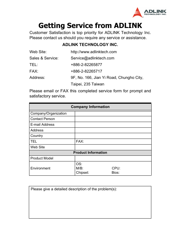
Getting Service from ADLINK Customer Satisfaction is top priority for ADLINK Technology Inc. Please contact us should you require any service or assistance. Web Site: Sales & Service: TEL: FAX: Address: ADLINK TECHNOLOGY INC. http://www.adlinktech.com Service@adlinktech.com +886-2-82265877 +886-2-82265717 9F, No. 166, Jian Yi Road, Chungho City, Taipei, 235 Taiwan Please email or FAX this completed service form for prompt and satisfactory service. Company Information Company/Organization Contact Person E-mail Address Address Country TEL Web Site Product Model Environment FAX: Product Information OS: M/B: CPU: Chipset: Bios: Please give a detailed description of the problem(s):
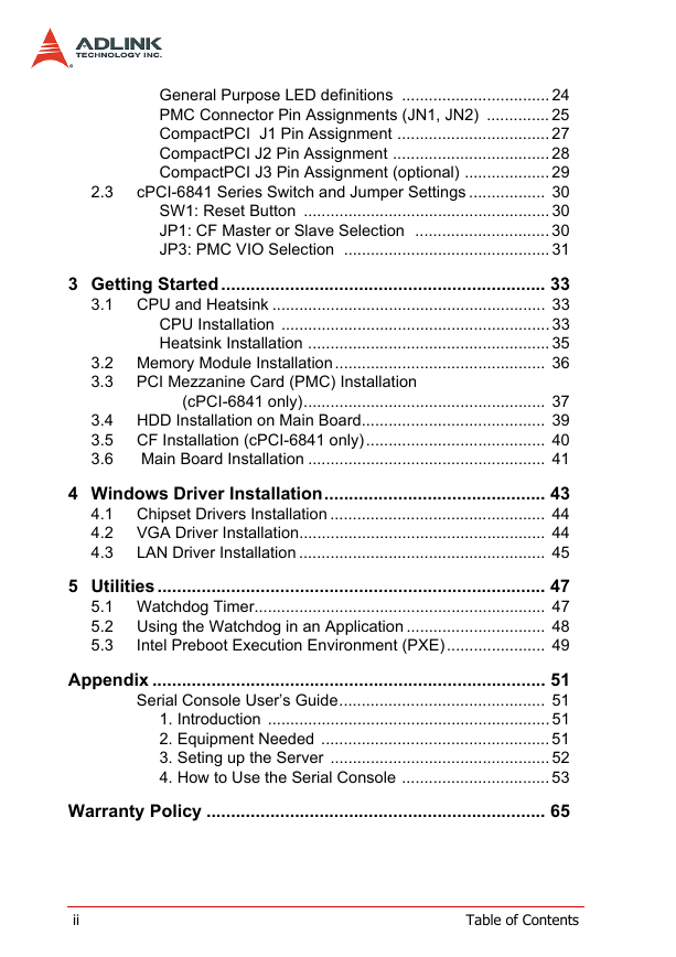
Table of Contents List of Tables.......................................................................... iii List of Figures ......................................................................... v 1 Introduction ........................................................................ 1 1.1 Main Functions .................................................................... 3 CPU Support ................................................................... 3 CompactPCI Bus Interface ............................................. 3 PCI Mezzanine Card (PMC) Interface ............................ 3 IDE and CompactFlash Interfaces .................................. 3 Gigabit Ethernet Ports .................................................... 4 Universal Serial Bus (USB) ............................................. 4 Serial I/O ......................................................................... 4 Keyboard/Mouse Controller ............................................ 4 FDD Interface ................................................................. 4 Watchdog Timer ............................................................. 5 Hardware Monitoring ...................................................... 5 Operating System Support ............................................. 5 Features............................................................................... 6 Product List.......................................................................... 7 Specifications....................................................................... 8 cPCI-6841 SBC Specifications ....................................... 8 I/O Connectivity ............................................................ 11 Unpacking Checklist .......................................................... 12 2 Jumpers and Connectors................................................ 13 cPCI-6841 Series Mechanical Drawings ........................... 14 cPCI-6841 Series Pin Assignments................................... 17 USB Connectors ........................................................... 17 VGA Connector ............................................................. 17 Ethernet (RJ-45) Connector .......................................... 18 PS2 Connector ............................................................. 19 RS-232 Serial Port Connector ..................................... 19 ...................................................................................... 19 DVI Connector .............................................................. 20 CompactFlash Connector ............................................. 21 Floppy Connector ......................................................... 22 IDE Connector .............................................................. 23 1.2 1.3 1.4 1.5 2.1 2.2 Table of Contents i
2.3 General Purpose LED definitions ................................. 24 PMC Connector Pin Assignments (JN1, JN2) .............. 25 CompactPCI J1 Pin Assignment .................................. 27 CompactPCI J2 Pin Assignment ................................... 28 CompactPCI J3 Pin Assignment (optional) ................... 29 cPCI-6841 Series Switch and Jumper Settings ................. 30 SW1: Reset Button ....................................................... 30 JP1: CF Master or Slave Selection .............................. 30 JP3: PMC VIO Selection .............................................. 31 3 Getting Started.................................................................. 33 CPU and Heatsink ............................................................. 33 CPU Installation ............................................................ 33 Heatsink Installation ...................................................... 35 3.2 Memory Module Installation............................................... 36 3.3 PCI Mezzanine Card (PMC) Installation 3.1 4.1 4.2 4.3 3.4 3.5 3.6 (cPCI-6841 only)...................................................... 37 HDD Installation on Main Board......................................... 39 CF Installation (cPCI-6841 only)........................................ 40 Main Board Installation ..................................................... 41 4 Windows Driver Installation............................................. 43 Chipset Drivers Installation ................................................ 44 VGA Driver Installation....................................................... 44 LAN Driver Installation ....................................................... 45 5 Utilities............................................................................... 47 5.1 Watchdog Timer................................................................. 47 Using the Watchdog in an Application ............................... 48 5.2 5.3 Intel Preboot Execution Environment (PXE)...................... 49 Appendix ................................................................................ 51 Serial Console User’s Guide.............................................. 51 1. Introduction ............................................................... 51 2. Equipment Needed ................................................... 51 3. Seting up the Server ................................................. 52 4. How to Use the Serial Console ................................. 53 Warranty Policy ..................................................................... 65 ii Table of Contents
List of Tables Table 1-1: Power Ratings ........................................................ 10 Table 1-2: I/O Connectivity Table ............................................ 11 Table 2-1: Ethernet LED Status ............................................... 18 Table 2-2: Switch and Jumper Functions ................................ 30 Table 2-3: JP1 Settings ........................................................... 30 Table 2-4: JP2 Settings ........................................................... 31 Table 2-5: JP3 Settings ........................................................... 31 Table 3-1: DDR SDRAM Memory Capacity ............................. 36 Table 6-1: Key Translation Sequences .................................... 64 Table 6-2: Special Commands ................................................ 64 List of Tables iii
iv List of Tables
分享到:
收藏