CDM324C RADAR TRANSCEIVER
Features
24 GHz K-band miniature I/Q transceiver
140MHz sweep FM input
2 x 4 patch antenna
2 balanced mixer with 50MHz bandwidth
Excellent noise cancelling ability though I/Q technology
Beam aperture 80°/34°
15dBm EIRP output power
25x25mm2 surface, <6.5mm thickness
Lowcost desig
Applications
Security systems
Direction sensitive movement detectors
Object speed measurement systems
Simple ranging detection using FSK
Industrial sensors
Description
CDM324C Actual Size
CDM324C is a 2 x 4 patch Doppler module with an
asymmetrical beam for lowcost short distance
applications. Its typical applications are move-
ment sensors in the security and presence
detection domain.
In building automation this module may be an
alternative for infrared PIR or AIR systems
thanks to its outstanding performance/cost
ratio.
The module is extremely small and lightweight.
With its IF bandwidth from DC to 50MHz it
opens many new applications. FSK is possible
thanks to the unique RFbeam oscillator design.
This allows to use this lowcost module even in
ranging applications.
Powerful starterkits (ST100 and ST200) with
signal conditioning and visualization on the
PC's are available.
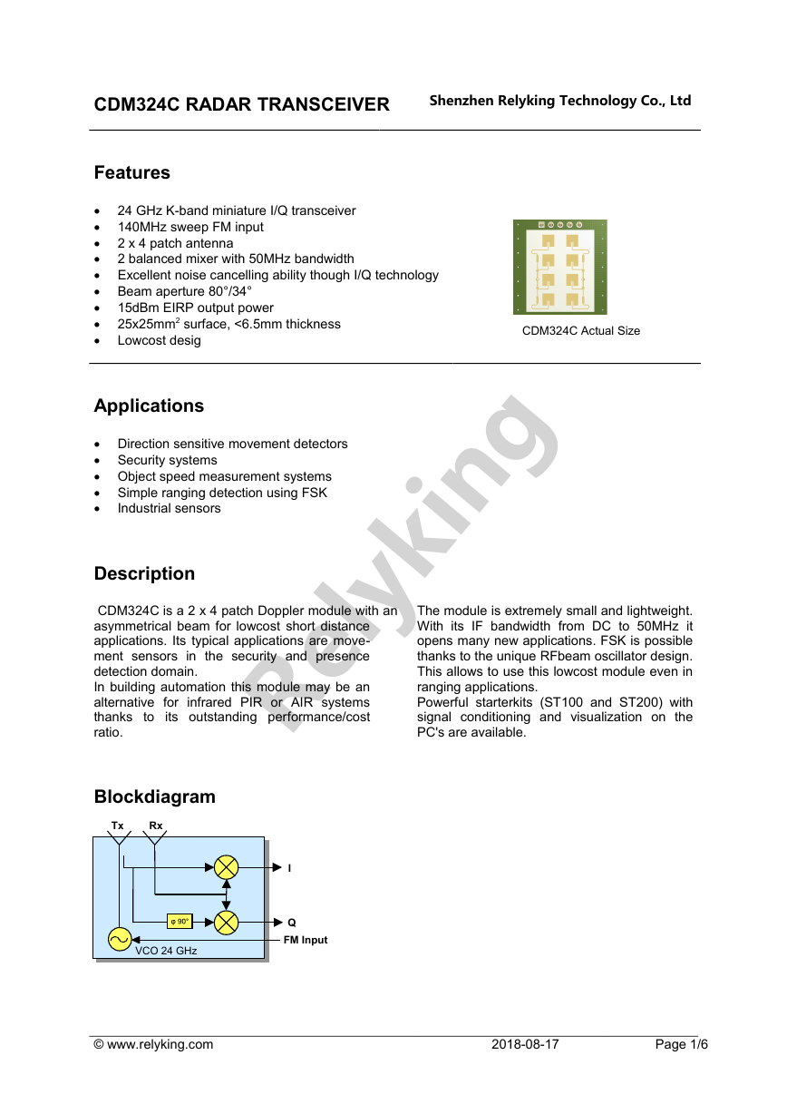
Blockdiagram
Tx
Rx
Fig. 1: Block diagram
VCO 24 GHz
I
Q
FM Input
© www.relyking.com
2018-08-17
Page 1/6
Relyking Shenzhen Relyking Technology Co., Ltd�
CDM324C RADAR TRANSCEIVER
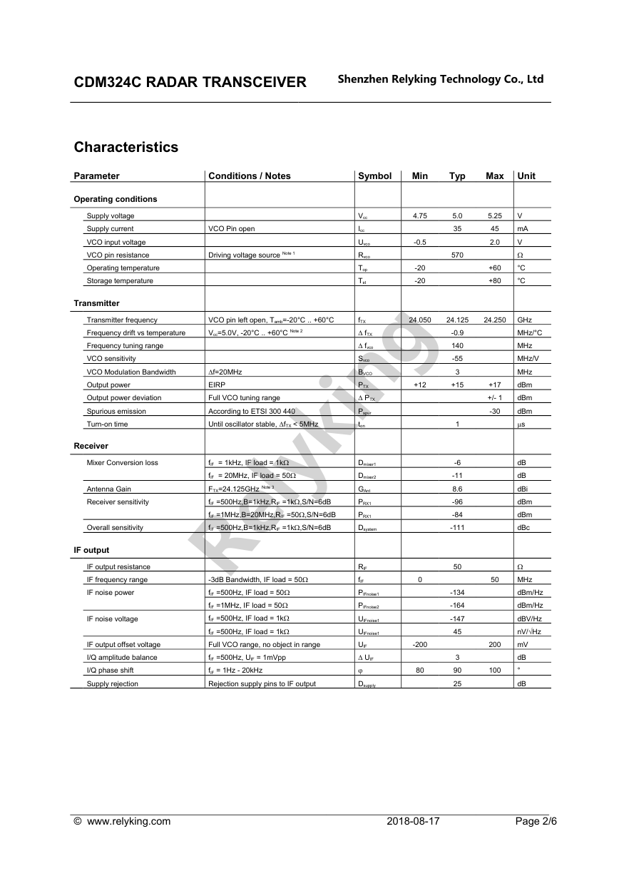
Characteristics
Parameter
Conditions / Notes
Symbol
Min
Typ
Max Unit
Operating conditions
Supply voltage
Supply current
VCO input voltage
VCO pin resistance
Operating temperature
Storage temperature
Transmitter
VCO Pin open
Driving voltage source Note 1
Transmitter frequency
Frequency drift vs temperature
Frequency tuning range
VCO sensitivity
VCO Modulation Bandwidth
Output power
Output power deviation
Spurious emission
Turn-on time
VCO pin left open, Tamb=-20°C .. +60°C
Vcc=5.0V, -20°C .. +60°C Note 2
f=20MHz
EIRP
Full VCO tuning range
According to ETSI 300 440
Until oscillator stable, fTX < 5MHz
Receiver
Mixer Conversion loss
Antenna Gain
Receiver sensitivity
Overall sensitivity
IF output
IF output resistance
IF frequency range
IF noise power
IF noise voltage
IF output offset voltage
I/Q amplitude balance
I/Q phase shift
Supply rejection
fIF = 1kHz, IF load = 1k
fIF = 20MHz, IF load = 50
FTX=24.125GHz Note 3
fIF =500Hz,B=1kHz,RIF =1k,S/N=6dB
fIF =1MHz,B=20MHz,RIF =50,S/N=6dB
fIF =500Hz,B=1kHz,RIF =1k,S/N=6dB
-3dB Bandwidth, IF load = 50
fIF =500Hz, IF load = 50
fIF =1MHz, IF load = 50
fIF =500Hz, IF load = 1k
fIF =500Hz, IF load = 1k
Full VCO range, no object in range
fIF =500Hz, UIF = 1mVpp
fIF = 1Hz - 20kHz
Rejection supply pins to IF output
Vcc
Icc
Uvco
Rvco
Top
Tst
fTX
fTX
fvco
Svco
BVCO
PTX
PTX
Pspur
ton
Dmixer1
Dmixer2
GAnt
PRX1
PRX1
Dsystem
RIF
fIF
PIFnoise1
PIFnoise2
UIFnoise1
UIFnoise1
UIF
UIF
Dsupply
5.0
35
570
4.75
-0.5
-20
-20
5.25
45
2.0
+60
+80
V
mA
V
°C
°C
24.050
24.125
24.250 GHz
-0.9
140
-55
3
+15
1
-6
-11
8.6
-96
-84
-111
50
-134
-164
-147
45
3
90
25
MHz/°C
MHz
MHz/V
MHz
dBm
dBm
dBm
s
dB
dB
dBi
dBm
dBm
dBc
MHz
dBm/Hz
dBm/Hz
dBV/Hz
nV/Hz
mV
dB
°
dB
+17
+/- 1
-30
50
200
100
+12
0
-200
80
© www.relyking.com
2018-08-17
Page 2/6
Relyking Shenzhen Relyking Technology Co., Ltd�
CDM324C RADAR TRANSCEIVER
Parameter
Antenna
Conditions / Notes
Symbol
Min
Typ
Max Unit
Horizontal -3dB beamwidth
Vertical -3dB beamwidth
Horiz. sidelobe suppression
Vertical sidelobe suppression
E-Plane
H-Plane
Body
Outline Dimensions
Weight
Connector
5pin single row jumper
W
W
D
D
-12
-12
80
34
-20
-20
25*25*6
4.5
°
°
dB
dB
mm3
g
Note 1 The VCO input has an internal voltage source with approx. 0.9VDC. For driving this pin it is necessary to source and
Note 2 Transmit frequency stays within 24.050 to 24.250GHz over the specified temperature range when the VCO pin
sink current
is left open
Note 3 Theoretical value, given by Design
Antenna System Diagram
This diagram shows module sensitivity in both azimuth and elevation directions. It incorporates
therefore the transmitter and receiver antenna characteristics.
Horizontal 80° , vertical 34°
at IF output voltage -6dB
(corresponds to -3dB Tx power)
80°
34°
Remarks:
The broader the antenna, the
narrower the beam.
Fig. 2: System diagram
© www.relyking.com
2018-08-17
Page 3/6
Relyking Shenzhen Relyking Technology Co., Ltd�
CDM324C RADAR TRANSCEIVER
FM Characteristics
VCO Voltage generates an output signal even without an object in range because of the finite isolation
between transmitter and receiver path. This effect is called self-mixing and leads to a DC signal that
depends on the carrier frequency.
Mixer offset voltages are also dependent on production tolerances.
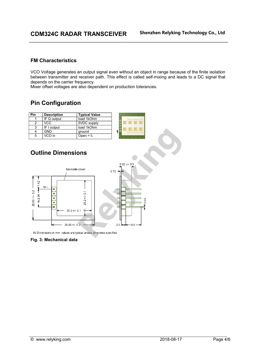
Pin Configuration
Pin
1
2
3
4
5
Description
IF Q output
VCC
IF I output
GND
VCO in
Typical Value
load 1kOhm
5VDC supply
load 1kOhm
ground
Open = f0
1
Outline Dimensions
Fig. 3: Mechanical data
© www.relyking.com
2018-08-17
Page 4/6
Relyking Shenzhen Relyking Technology Co., Ltd�
CDM324C RADAR TRANSCEIVER
Application Notes
Sensitivity and Maximum Range
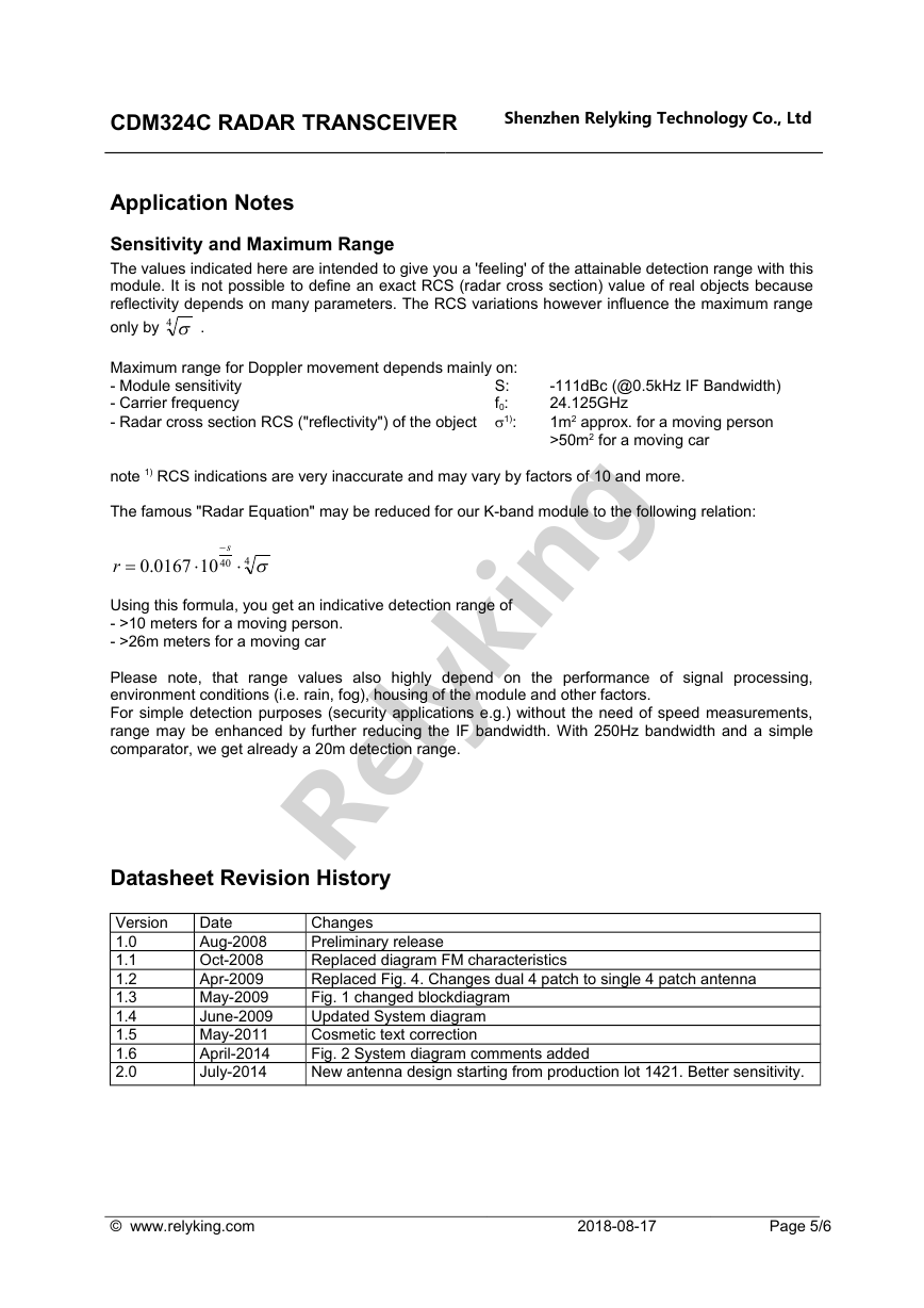
The values indicated here are intended to give you a 'feeling' of the attainable detection range with this
module. It is not possible to define an exact RCS (radar cross section) value of real objects because
reflectivity depends on many parameters. The RCS variations however influence the maximum range
only by 4 .
Maximum range for Doppler movement depends mainly on:
S:
- Module sensitivity
- Carrier frequency
f0:
- Radar cross section RCS ("reflectivity") of the object 1):
-111dBc (@0.5kHz IF Bandwidth)
24.125GHz
1m2 approx. for a moving person
>50m2 for a moving car
note 1) RCS indications are very inaccurate and may vary by factors of 10 and more.
The famous "Radar Equation" may be reduced for our K-band module to the following relation:
r
.0
0167
s
4010
4
Using this formula, you get an indicative detection range of
- >10 meters for a moving person.
- >26m meters for a moving car
Please note, that range values also highly depend on the performance of signal processing,
environment conditions (i.e. rain, fog), housing of the module and other factors.
For simple detection purposes (security applications e.g.) without the need of speed measurements,
range may be enhanced by further reducing the IF bandwidth. With 250Hz bandwidth and a simple
comparator, we get already a 20m detection range.
Datasheet Revision History
Version
1.0
1.1
1.2
1.3
1.4
1.5
1.6
2.0
Date
Aug-2008
Oct-2008
Apr-2009
May-2009
June-2009
May-2011
April-2014
July-2014
Changes
Preliminary release
Replaced diagram FM characteristics
Replaced Fig. 4. Changes dual 4 patch to single 4 patch antenna
Fig. 1 changed blockdiagram
Updated System diagram
Cosmetic text correction
Fig. 2 System diagram comments added
New antenna design starting from production lot 1421. Better sensitivity.
© www.relyking.com
2018-08-17
Page 5/6
Relyking Shenzhen Relyking Technology Co., Ltd�
CDM324C RADAR TRANSCEIVER
© www.relyking.com
2018-08-17
Page 6/6
Relyking Shenzhen Relyking Technology Co., Ltd�



 2023年江西萍乡中考道德与法治真题及答案.doc
 2012年重庆南川中考生物真题及答案.doc
 2013年江西师范大学地理学综合及文艺理论基础考研真题.doc
 2020年四川甘孜小升初语文真题及答案I卷.doc
 2020年注册岩土工程师专业基础考试真题及答案.doc
 2023-2024学年福建省厦门市九年级上学期数学月考试题及答案.doc
 2021-2022学年辽宁省沈阳市大东区九年级上学期语文期末试题及答案.doc
 2022-2023学年北京东城区初三第一学期物理期末试卷及答案.doc
 2018上半年江西教师资格初中地理学科知识与教学能力真题及答案.doc
 2012年河北国家公务员申论考试真题及答案-省级.doc
 2020-2021学年江苏省扬州市江都区邵樊片九年级上学期数学第一次质量检测试题及答案.doc
 2022下半年黑龙江教师资格证中学综合素质真题及答案.doc