logo资料库

IMX214-0AQH5-C_3.0.0_Data_Sheet.pdf

第1页 / 共48页
第2页 / 共48页
第3页 / 共48页
第4页 / 共48页
第5页 / 共48页
第6页 / 共48页
第7页 / 共48页
第8页 / 共48页
资料共48页,剩余部分请下载后查看
General description and application
Functions and Features
Device Structure
Absolute Maximum Ratings
Recommended Operating Voltage
USE RESTRICTION NOTICE
Chip Center and Optical Center
Pin Coordinates
Pin Description
Input/Output Equivalent Circuit
Peripheral Circuit Diagram
Functional Description
System Outline
Control register setting by the serial communication
2-wire Serial Communication Operation Specifications
Communication Protocol
Clock generation and PLL
Clock System Diagram
Description of operation clocks
INCK
VTCK, OPCK : PLL output
VTPXCK Clock
OPPXCK Clock
Image Readout Operation
Phyical alignment of imaging pixel array
Color coding and order of reading image date
Output Image Format
Embedded Data Line control
STATS data control
Image size of mode
Description about operation mode
Image area control capabilities
Gain setting
Image compensation function
Defect Pixel Correction
Adaptive Tone Reproduction (ATR)
Chroma Noise Resuction (CNR)
Luminance Noise Resuction (LNR)
Miscellaneous functions
Thermal Meter
Test pattern output and type of test pattern
Long Exposure Setting
OTP (One Time Programable Read Only Memory)
3D Mode
Flash light control sequence
External pixel power supply capability
Image signal interface
MIPI transmitter
How to operate IMX214
Power on Reset
Power on sequense
Power on slew rate
Start up sequence with 2-wire serial communication (external reset)
Start up sequence with 2-wire serial communication (power on reset)
Power down sequence
Power down sequence with 2-wire serial communication
Register Map
Electrical Characteristics
DC characteristics
AC Characteristics
Master Clock Waveform Diagram
INCK (EXTCLK) Square Waveform Input Specifications
INCK (EXTCLK) Sine Waveform Input Specifications
PLL block characteristics
Definition of settling time of PLL block
2-wire serial communication block characteristics
Current consumption and standby current
Spectral Sensitivity Characteristic
Image Sensor Characteristics
Zone Definition used for specifying image sensor characteristics
Measurement Method for Image Sensor Characteristics
Measurement conditions
Color Coding of This Image Sensor and Readout
Definition of Standard Imaging Conditions
Standard imaging condition I
Standard imaging condition II
Standard imaging condition III
Measurement method
Sensitivity
Sensitivity ratio
Saturation signal
Video signal shading
Dark signal
Spot Pixel Specification
Notice on White Pixels Specifications
Measurement Method for Spot Pixels
Spot Pixel Pattern Specifications
SPS_1 Black or white pixels at high light
SPS_2 White pixels in the dark
CRA Characteristics of Recommended Lens
Notes on Handling
Notes of Caution
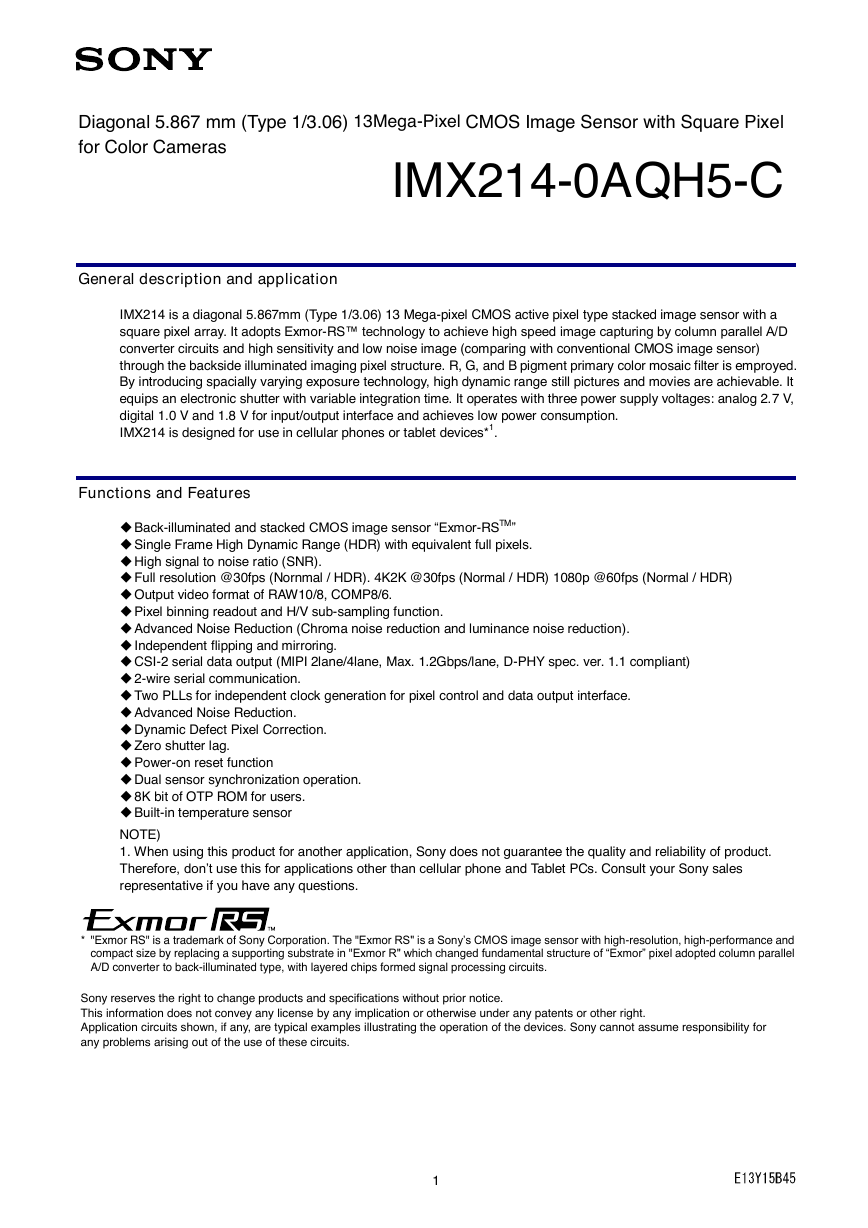
Diagonal 5.867 mm (Type 1/3.06) 13Mega-Pixel CMOS Image Sensor with Square Pixel for Color Cameras General description and application IMX214-0AQH5-C IMX214 is a diagonal 5.867mm (Type 1/3.06) 13 Mega-pixel CMOS active pixel type stacked image sensor with a square pixel array. It adopts Exmor-RS™ technology to achieve high speed image capturing by column parallel A/D converter circuits and high sensitivity and low noise image (comparing with conventional CMOS image sensor) through the backside illuminated imaging pixel structure. R, G, and B pigment primary color mosaic filter is emproyed. By introducing spacially varying exposure technology, high dynamic range still pictures and movies are achievable. It equips an electronic shutter with variable integration time. It operates with three power supply voltages: analog 2.7 V, digital 1.0 V and 1.8 V for input/output interface and achieves low power consumption. IMX214 is designed for use in cellular phones or tablet devices*1. Functions and Features ◆ Back-illuminated and stacked CMOS image sensor “Exmor-RSTM” ◆ Single Frame High Dynamic Range (HDR) with equivalent full pixels. ◆ High signal to noise ratio (SNR). ◆ Full resolution @30fps (Nornmal / HDR). 4K2K @30fps (Normal / HDR) 1080p @60fps (Normal / HDR) ◆ Output video format of RAW10/8, COMP8/6. ◆ Pixel binning readout and H/V sub-sampling function. ◆ Advanced Noise Reduction (Chroma noise reduction and luminance noise reduction). ◆ Independent flipping and mirroring. ◆ CSI-2 serial data output (MIPI 2lane/4lane, Max. 1.2Gbps/lane, D-PHY spec. ver. 1.1 compliant) ◆ 2-wire serial communication. ◆ Two PLLs for independent clock generation for pixel control and data output interface. ◆ Advanced Noise Reduction. ◆ Dynamic Defect Pixel Correction. ◆ Zero shutter lag. ◆ Power-on reset function ◆ Dual sensor synchronization operation. ◆ 8K bit of OTP ROM for users. ◆ Built-in temperature sensor NOTE) 1. When using this product for another application, Sony does not guarantee the quality and reliability of product. Therefore, don’t use this for applications other than cellular phone and Tablet PCs. Consult your Sony sales representative if you have any questions. * "Exmor RS" is a trademark of Sony Corporation. The "Exmor RS" is a Sony’s CMOS image sensor with high-resolution, high-performance and compact size by replacing a supporting substrate in "Exmor R" which changed fundamental structure of “Exmor” pixel adopted column parallel A/D converter to back-illuminated type, with layered chips formed signal processing circuits. Sony reserves the right to change products and specifications without prior notice. This information does not convey any license by any implication or otherwise under any patents or other right. Application circuits shown, if any, are typical examples illustrating the operation of the devices. Sony cannot assume responsibility for any problems arising out of the use of these circuits. 1
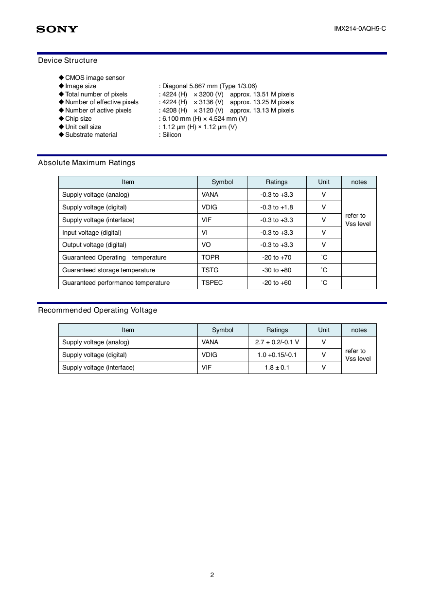
IMX214-0AQH5-C Device Structure ◆ CMOS image sensor ◆ Image size ◆ Total number of pixels ◆ Number of effective pixels ◆ Number of active pixels ◆ Chip size ◆ Unit cell size ◆ Substrate material Absolute Maximum Ratings : Diagonal 5.867 mm (Type 1/3.06) : 4224 (H) × 3200 (V) approx. 13.51 M pixels : 4224 (H) × 3136 (V) approx. 13.25 M pixels : 4208 (H) × 3120 (V) approx. 13.13 M pixels : 6.100 mm (H) × 4.524 mm (V) : 1.12 μm (H) × 1.12 μm (V) : Silicon Item Symbol Ratings Unit notes Supply voltage (analog) Supply voltage (digital) Supply voltage (interface) Input voltage (digital) Output voltage (digital) Guaranteed Operating temperature Guaranteed storage temperature VANA VDIG VIF VI VO TOPR TSTG Guaranteed performance temperature TSPEC -0.3 to +3.3 -0.3 to +1.8 -0.3 to +3.3 -0.3 to +3.3 -0.3 to +3.3 -20 to +70 -30 to +80 -20 to +60 V V V V V ˚C ˚C ˚C refer to Vss level Recommended Operating Voltage Item Symbol Ratings Unit notes Supply voltage (analog) Supply voltage (digital) Supply voltage (interface) VANA VDIG VIF 2.7 + 0.2/-0.1 V 1.0 +0.15/-0.1 1.8 ± 0.1 V V V refer to Vss level 2
USE RESTRICTION NOTICE IMX214-0AQH5-C This USE RESTRICTION NOTICE ("Notice") is for customers who are considering or currently using the image sensor products ("Products") set forth in this specifications book. Sony Corporation ("Sony") may, at any time, modify this Notice which will be available to you in the latest specifications book for the Products. You should abide by the latest version of this Notice. If a Sony subsidiary or distributor has its own use restriction notice on the Products, such a use restriction notice will additionally apply between you and the subsidiary or distributor. You should consult a sales representative of the subsidiary or distributor of Sony on such a use restriction notice when you consider using the Products. Use Restrictions  The Products are intended for incorporation into such general electronic equipment as office products, communication products, measurement products, and home electronics products in accordance with the terms and conditions set forth in this specifications book and otherwise notified by Sony from time to time.  You should not use the Products for critical applications which may pose a life- or injury-threatening risk or are highly likely to cause significant property damage in the event of failure of the Products. You should consult your sales representative beforehand when you consider using the Products for such critical applications. In addition, you should not use the Products in weapon or military equipment.  Sony disclaims and does not assume any liability and damages arising out of misuse, improper use, modification, use of the Products for the above-mentioned critical applications, weapon and military equipment, or any deviation from the requirements set forth in this specifications book. Design for Safety  Sony is making continuous efforts to further improve the quality and reliability of the Products; however, failure of a certain percentage of the Products is inevitable. Therefore, you should take sufficient care to ensure the safe design of your products such as component redundancy, anti-conflagration features, and features to prevent mis-operation in order to avoid accidents resulting in injury or death, fire or other social damage as a result of such failure. Export Control  If the Products are controlled items under the export control laws or regulations of various countries, approval may be required for the export of the Products under the said laws or regulations. You should be responsible for compliance with the said laws or regulations. No License Implied  The technical information shown in this specifications book is for your reference purposes only. The availability of this specifications book shall not be construed as giving any indication that Sony and its licensors will license any intellectual property rights in such information by any implication or otherwise. Sony will not assume responsibility for any problems in connection with your use of such information or for any infringement of third-party rights due to the same. It is therefore your sole legal and financial responsibility to resolve any such problems and infringement. Governing Law  This Notice shall be governed by and construed in accordance with the laws of Japan, without reference to principles of conflict of laws or choice of laws. All controversies and disputes arising out of or relating to this Notice shall be submitted to the exclusive jurisdiction of the Tokyo District Court in Japan as the court of first instance. Other Applicable Terms and Conditions  The terms and conditions in the Sony additional specifications, which will be made available to you when you order the Products, shall also be applicable to your use of the Products as well as to this specifications book. You should review those terms and conditions when you consider purchasing and/or using the Products. 3
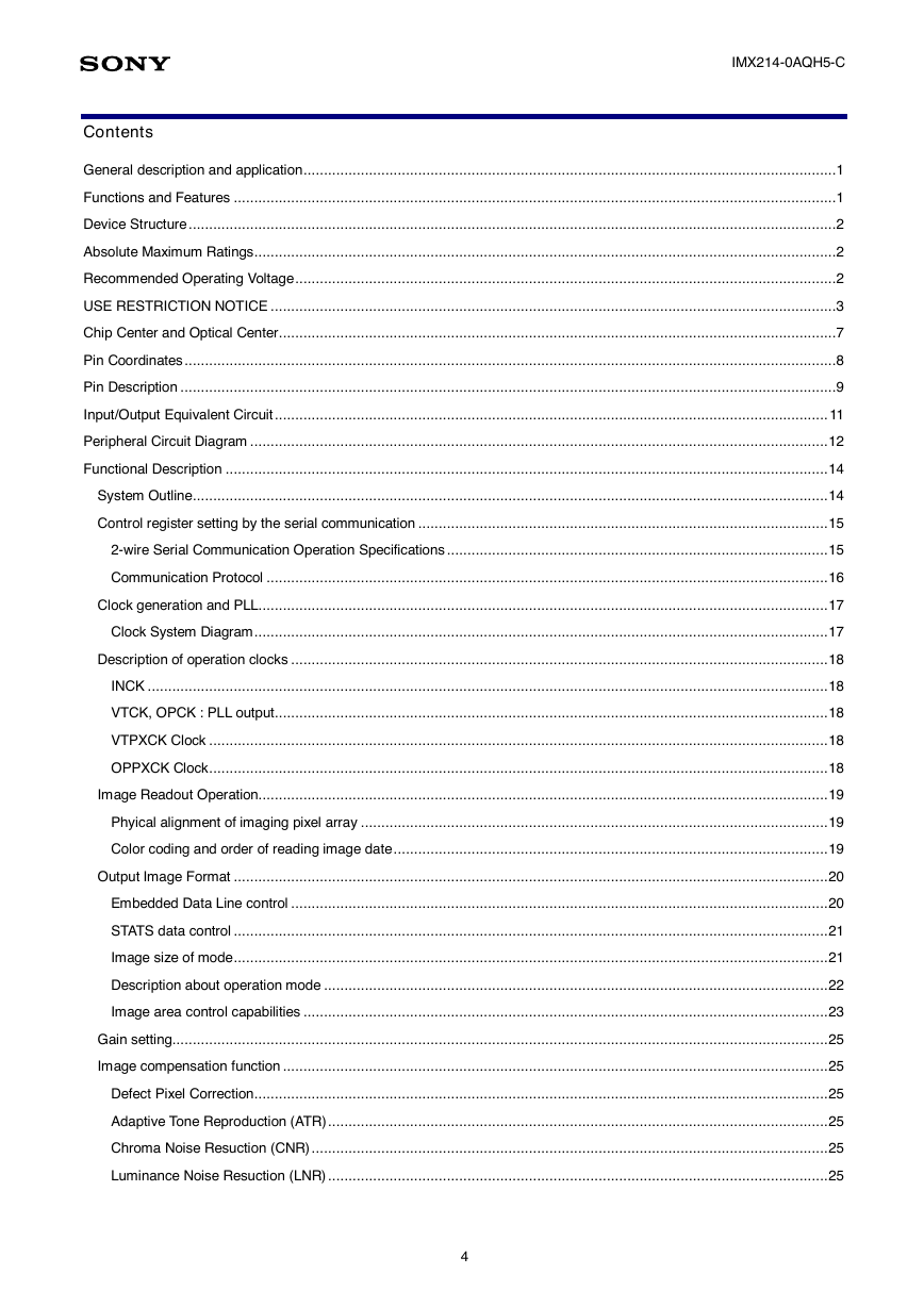
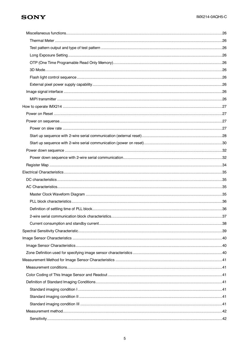
IMX214-0AQH5-C Contents General description and application ..................................................................................................................................1 Functions and Features ...................................................................................................................................................1 Device Structure ..............................................................................................................................................................2 Absolute Maximum Ratings ..............................................................................................................................................2 Recommended Operating Voltage ....................................................................................................................................2 USE RESTRICTION NOTICE ..........................................................................................................................................3 Chip Center and Optical Center ........................................................................................................................................7 Pin Coordinates ...............................................................................................................................................................8 Pin Description ................................................................................................................................................................9 Input/Output Equivalent Circuit ....................................................................................................................................... 11 Peripheral Circuit Diagram ............................................................................................................................................. 12 Functional Description ................................................................................................................................................... 14 System Outline ........................................................................................................................................................... 14 Control register setting by the serial communication .................................................................................................... 15 2-wire Serial Communication Operation Specifications ............................................................................................. 15 Communication Protocol ......................................................................................................................................... 16 Clock generation and PLL........................................................................................................................................... 17 Clock System Diagram ............................................................................................................................................ 17 Description of operation clocks ................................................................................................................................... 18 INCK ...................................................................................................................................................................... 18 VTCK, OPCK : PLL output ....................................................................................................................................... 18 VTPXCK Clock ....................................................................................................................................................... 18 OPPXCK Clock ....................................................................................................................................................... 18 Image Readout Operation........................................................................................................................................... 19 Phyical alignment of imaging pixel array .................................................................................................................. 19 Color coding and order of reading image date .......................................................................................................... 19 Output Image Format ................................................................................................................................................. 20 Embedded Data Line control ................................................................................................................................... 20 STATS data control ................................................................................................................................................. 21 Image size of mode ................................................................................................................................................. 21 Description about operation mode ........................................................................................................................... 22 Image area control capabilities ................................................................................................................................ 23 Gain setting................................................................................................................................................................ 25 Image compensation function ..................................................................................................................................... 25 Defect Pixel Correction ............................................................................................................................................ 25 Adaptive Tone Reproduction (ATR) .......................................................................................................................... 25 Chroma Noise Resuction (CNR) .............................................................................................................................. 25 Luminance Noise Resuction (LNR) .......................................................................................................................... 25 4
IMX214-0AQH5-C Miscellaneous functions.............................................................................................................................................. 26 Thermal Meter ........................................................................................................................................................ 26 Test pattern output and type of test pattern .............................................................................................................. 26 Long Exposure Setting ............................................................................................................................................ 26 OTP (One Time Programable Read Only Memory) ................................................................................................... 26 3D Mode ................................................................................................................................................................. 26 Flash light control sequence .................................................................................................................................... 26 External pixel power supply capability ...................................................................................................................... 26 Image signal interface ................................................................................................................................................ 26 MIPI transmitter ...................................................................................................................................................... 26 How to operate IMX214 ................................................................................................................................................. 27 Power on Reset ......................................................................................................................................................... 27 Power on sequense .................................................................................................................................................... 27 Power on slew rate ................................................................................................................................................. 27 Start up sequence with 2-wire serial communication (external reset) ......................................................................... 28 Start up sequence with 2-wire serial communication (power on reset) ....................................................................... 30 Power down sequence ............................................................................................................................................... 32 Power down sequence with 2-wire serial communication .......................................................................................... 32 Register Map ............................................................................................................................................................. 34 Electrical Characteristics ................................................................................................................................................ 35 DC characteristics ...................................................................................................................................................... 35 AC Characteristics...................................................................................................................................................... 35 Master Clock Waveform Diagram ............................................................................................................................ 35 PLL block characteristics ......................................................................................................................................... 36 Definition of settling time of PLL block ...................................................................................................................... 36 2-wire serial communication block characteristics..................................................................................................... 37 Current consumption and standby current ................................................................................................................ 38 Spectral Sensitivity Characteristic ................................................................................................................................... 39 Image Sensor Characteristics ........................................................................................................................................ 40 Image Sensor Characteristics ..................................................................................................................................... 40 Zone Definition used for specifying image sensor characteristics ................................................................................. 40 Measurement Method for Image Sensor Characteristics ................................................................................................. 41 Measurement conditions ............................................................................................................................................. 41 Color Coding of This Image Sensor and Readout ........................................................................................................ 41 Definition of Standard Imaging Conditions ................................................................................................................... 41 Standard imaging condition I ................................................................................................................................... 41 Standard imaging condition II .................................................................................................................................. 41 Standard imaging condition III ................................................................................................................................. 41 Measurement method................................................................................................................................................. 42 Sensitivity ............................................................................................................................................................... 42 5
IMX214-0AQH5-C Sensitivity ratio........................................................................................................................................................ 42 Saturation signal ..................................................................................................................................................... 42 Video signal shading ............................................................................................................................................... 42 Dark signal ............................................................................................................................................................. 42 Spot Pixel Specification.................................................................................................................................................. 43 Notice on White Pixels Specifications .......................................................................................................................... 44 Measurement Method for Spot Pixels .......................................................................................................................... 45 Spot Pixel Pattern Specifications ................................................................................................................................ 45 SPS_1 Black or white pixels at high light .................................................................................................................. 45 SPS_2 White pixels in the dark ................................................................................................................................ 45 CRA Characteristics of Recommended Lens .................................................................................................................. 46 Notes on Handling ......................................................................................................................................................... 47 Notes of Caution ............................................................................................................................................................ 48 6
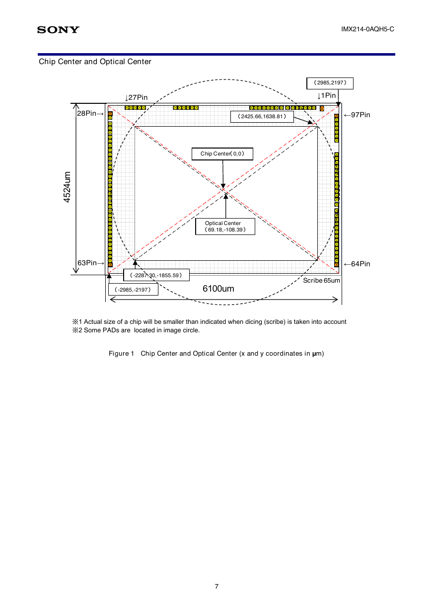
IMX214-0AQH5-C Chip Center and Optical Center ↓27Pin 28Pin→ (2985,2197) ↓1Pin (2425.66,1638.81) ←97Pin m u 4 2 5 4 Chip Center(0,0) Optical Center (69.18,-108.39) 63Pin→ (-2287.30,-1855.59) (-2985,-2197) 6100um ←64Pin Scribe 65um ※1 Actual size of a chip will be smaller than indicated when dicing (scribe) is taken into account ※2 Some PADs are located in image circle. Figure 1 Chip Center and Optical Center (x and y coordinates in μm) 7
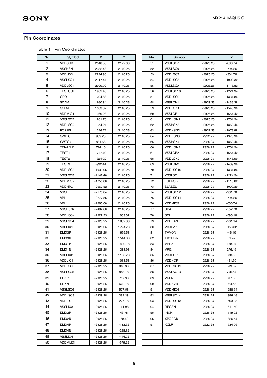
IMX214-0AQH5-C No. Symbol X Y 51 52 53 54 55 56 57 58 59 60 61 62 63 64 65 66 67 68 69 70 71 72 73 74 75 76 77 78 79 80 81 82 83 84 85 86 87 88 89 90 91 92 93 94 95 96 97 VSSLSC7 VSSLSC8 VDDLSC7 VDDLSC8 VSSLSC9 -2928.25 -686.74 -2928.25 -794.26 -2928.25 -901.78 -2928.25 -1009.30 -2928.25 -1116.82 VSSLSC10 -2928.25 -1224.34 VDDLSC9 VSSLCN1 VDDLCN1 VSSLCB1 VDDHCM1 VSSHSN3 VDDHSN2 VDDHSN3 VSSHSN4 VDDHCM2 VSSLCB2 VDDLCN2 VSSLCN2 VDDLSC10 VSSLSC11 FSTROBE SLASEL VSSLSC12 VDDLSC11 VDDMIO3 SDA SCL VDDHAN VSSHAN TVMON TVCDSIN VRL2 VPI2 VSSHCP VDDHCP VDDLSC12 VSSLSC13 VREN VDDHVR VDDMIO4 VSSLSC14 VDDLSC13 REGEN INCK XPORCD XCLR -2928.25 -1331.86 -2928.25 -1439.38 -2928.25 -1546.90 -2928.25 -1654.42 -2928.25 -1761.94 -2928.25 -1869.46 -2922.25 -1976.98 2922.25 -1976.98 2928.25 -1869.46 2928.25 -1761.94 2928.25 -1654.42 2928.25 -1546.90 2928.25 -1439.38 2928.25 -1331.86 2928.25 -1224.34 2928.25 -1116.82 2928.25 -1009.30 2928.25 2928.25 2928.25 -901.78 -794.26 -686.74 2928.25 -552.70 2928.25 -395.18 2928.25 -261.14 2928.25 -153.62 2928.25 2928.25 2928.25 2928.25 2928.25 2928.25 2928.25 2928.25 2928.25 2928.25 -46.10 61.42 168.94 276.46 383.98 491.50 599.02 706.54 817.06 924.58 2928.25 1288.94 2928.25 1396.46 2928.25 1503.98 2928.25 1611.50 2928.25 1719.02 2928.25 1826.54 2922.25 1934.06 Pin Coordinates Table 1 Pin Coordinates No. Symbol X Y 1 2 3 4 5 6 7 8 9 10 11 12 13 14 15 16 17 18 19 20 21 22 23 24 25 26 27 28 29 30 31 32 33 34 35 36 37 38 39 40 41 42 43 44 45 46 47 48 49 50 VDDSUB VSSHSN1 VDDHSN1 VSSLSC1 VDDLSC1 TESTOUT GPO SDAM SCLM VDDMIO1 VSSLSC2 VDDLSC2 POREN SWDIO SWTCK TENABLE TEST1 TEST2 TEST3 VDDLSC3 VSSLSC3 VDDMIO2 VDDHPL VSSHPL VPI1 VRL1 VSSHSN2 VDDLSC4 VSSLSC4 VSSLIO1 DMO3P DMO3N DMO1P DMO1N VSSLIO2 VDDLIO1 VDDLSC5 VSSLSC5 DCKP DCKN VSSLSC6 VDDLSC6 VDDLIO2 VSSLIO3 DMO2P DMO2N DMO4P DMO4N 2548.50 2122.00 2332.48 2140.25 2224.96 2140.25 2117.44 2140.25 2009.92 2140.25 1902.40 2140.25 1794.88 2140.25 1660.84 2140.25 1503.32 2140.25 1369.28 2140.25 1261.76 2140.25 1154.24 2140.25 1046.72 2140.25 939.20 831.68 724.16 -717.40 -824.92 -932.44 2140.25 2140.25 2140.25 2140.25 2140.25 2140.25 -1039.96 2140.25 -1147.48 2140.25 -1255.00 2140.25 -2062.52 2140.25 -2170.04 2140.25 -2277.56 2140.25 -2385.08 2140.25 -2492.60 2140.25 -2922.25 1989.82 -2928.25 1882.30 -2928.25 1774.78 -2928.25 1659.58 -2928.25 1544.38 -2928.25 1429.18 -2928.25 1313.98 -2928.25 1198.78 -2928.25 1083.58 -2928.25 -2928.25 -2928.25 -2928.25 -2928.25 -2928.25 -2928.25 -2928.25 -2928.25 -2928.25 968.38 853.18 737.98 622.78 507.58 392.38 277.18 161.98 46.78 -68.42 -2928.25 -183.62 -2928.25 -298.82 VSSLIO4 -2928.25 -414.02 VDDMMD1 -2928.25 -579.22 8
分享到:
收藏