lecture 1
Introduction to Radar Systems ��
Disclaimer of Endorsement and Liability
Introduction to Radar Systems ��Introduction
Acknowledgement
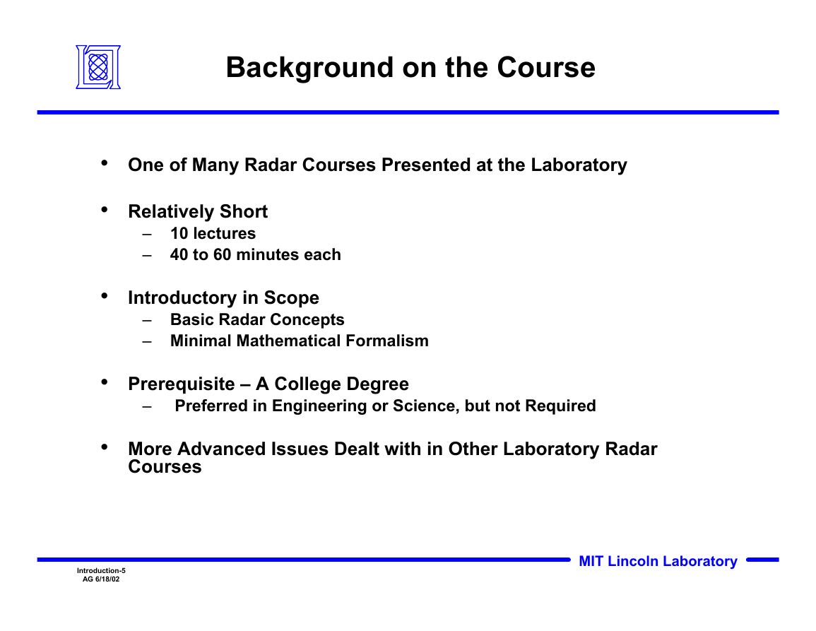
Background on the Course
Outline
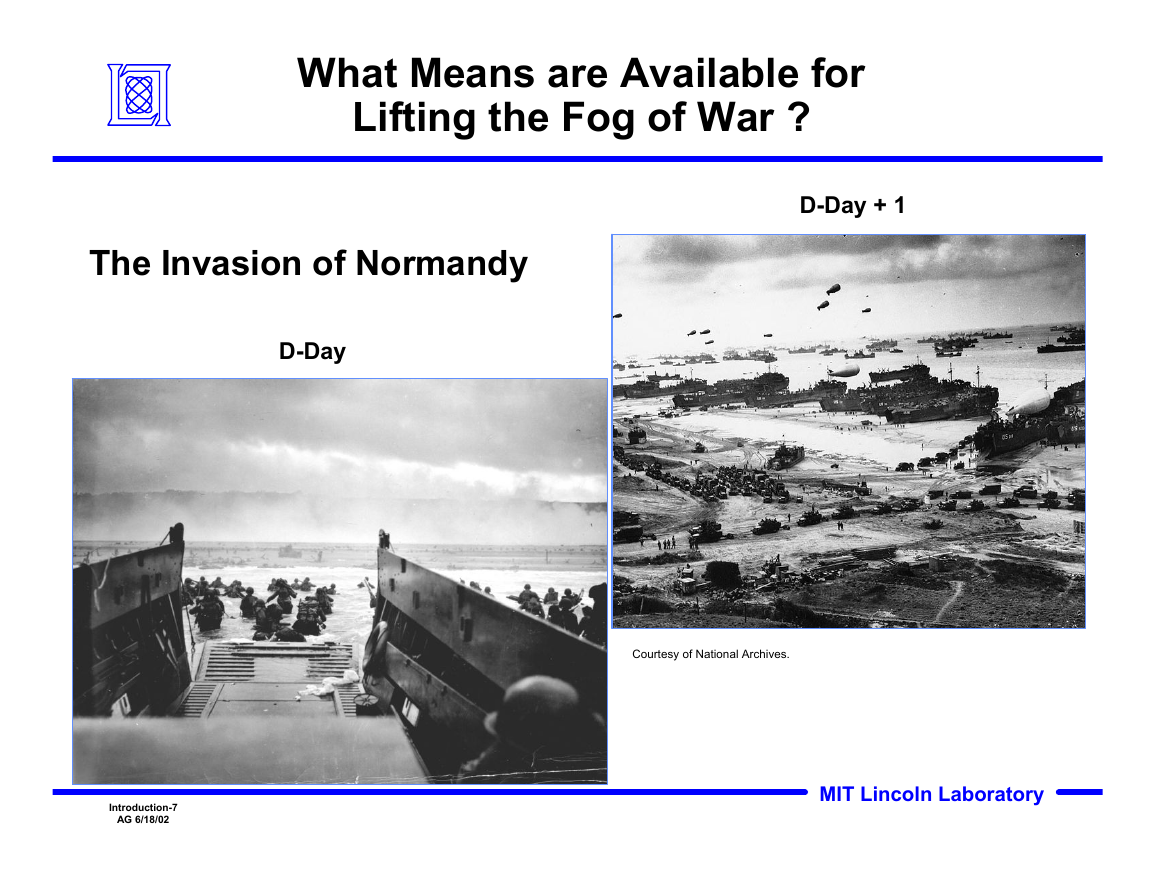
What Means are Available for �Lifting the Fog of War ?
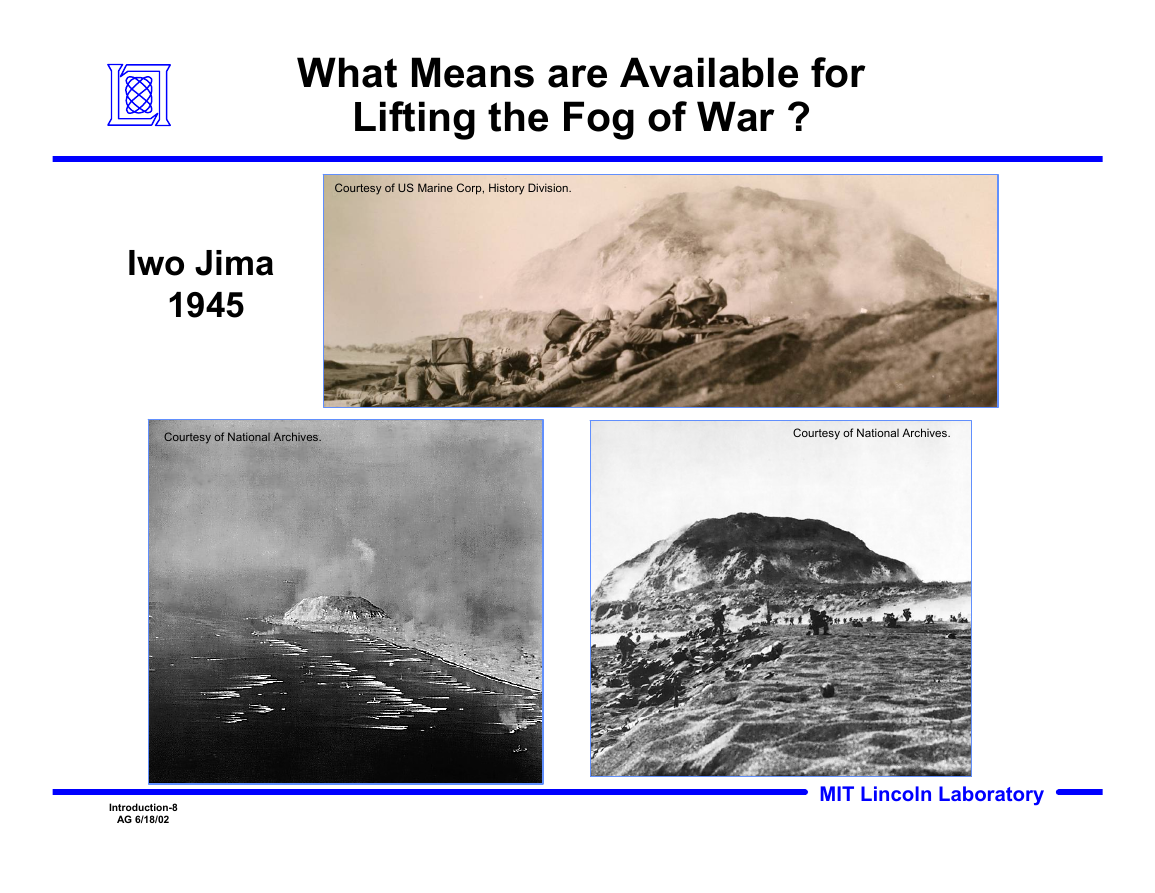
What Means are Available for �Lifting the Fog of War ?
Military Means of Sensing
Early Days of Radar�Chain Home Radar, Deployment Began 1936
Chain Home Radar System
Chain Home Transmit & Receive Antennas
Radar and “The Battle of Britain”
Slide Number 14
Slide Number 15
Slide Number 16
Outline
RADAR�RAdio Detection And Ranging
Electromagnetic Waves
Properties of Waves�Relationship Between Frequency and Wavelength
Properties of Waves�Phase and Amplitude
Properties of Waves�Constructive vs. Destructive Addition
Polarization
Radar Frequency Bands
IEEE Standard Radar Bands �(Typical Use)
Radar Block Diagram
Radar Range Equation
Signal-to-Noise Ratio
What the #@!*% is a dB?
Pulsed Radar�Terminology and Concepts
Pulsed Radar�Terminology and Concepts
Brief Mathematical Digression�Scientific Notation and Greek Prefixes
Radar Waveforms
Radar Waveforms (cont’d.)
Radar Range Measurement
Antenna Gain
Propagation Effects on Radar Performance
Radar Cross Section (RCS)
Signal Processing�Pulse Compression
Bandwidth
Why Bandwidth is Important
Detection of Signals in Noise
Coherent Integration
Doppler Effect
Doppler Shift Concept
Why Doppler is Important
Clutter Doppler Spectra
Radar Block Diagram
Outline
Introduction to Radar Systems Tutorial�Agenda
References
lecture 2
Introduction to Radar Systems �� The Radar Equation
Disclaimer of Endorsement and Liability
Introduction – The Radar Range Equation
Outline
Radar Range Equation
Radar Range Equation (continued)
Definition of Radar Cross Section (RCS or s)
Radar Range Equation (continued)
Sources of Noise Received by Radar
Radar Range Equation (continued)
System Noise Temperature
Outline
Track Radar Range Equation
Track & Search Radar Range Equations
Slide Number 15
Slide Number 16
Slide Number 17
Slide Number 18
Slide Number 19
Slide Number 20
Slide Number 21
Outline
Loss Terms for Radar Equation
Examples of Losses in Radar Equation
Examples of Losses in Radar Equation
Outline
Example - Airport Surveillance Radar
Example - Airport Surveillance Radar
Example - Airport Surveillance Radar
Outline
Slide Number 31
Slide Number 32
Radar Equation and Detection Process
Slide Number 34
References
lecture 3
Introduction to Radar Systems ��Propagation Effects�
Disclaimer of Endorsement and Liability
Radar Block Diagram
Radar Classes
Propagation Effects on Radar Performance
What’s in the Soup?�
Outline
Atmospheric Attenuation at Sea Level
Attenuation in Rain and Fog
Outline
Interference Basics
Propagation over a Plane Earth
Multipath Alters Radar Detection Range
Multipath is Frequency Dependent
Outline
Diffraction
Propagation Over Round Earth
Combined Diffraction and Multipath vs Radar Frequency
Outline
Refraction of Radar Beams
Earth’s Radius Modified to Account for Refraction Effects
Anomalous Propagation
Ducting Effects on Target Detection
Ducted Clutter from New England
Radar Propagation Effects Summary
References
lecture 4
Introduction to Radar Systems ��Target Radar Cross Section
Disclaimer of Endorsement and Liability
Generic Radar Block Diagram
Definition of Radar Cross Section (RCS or s)
Factors Determining RCS
Threat’s View of the Radar �Range Equation
Outline
Radar Cross Section of Sphere
Backscatter of Short Pulse from Sphere
Radar Cross Section of Typical RV
Examples of Radar Cross Sections
Outline
Slide Number 13
Description of Sample Cases on Video
FD-TD Simulation of Scattering by Strip
Slide Number 16
FD-TD Simulation of Scattering by Strip
FD-TD Simulation of Scattering by Strip
Slide Number 19
FD-TD Simulation of Scattering by Strip
FD-TD Simulation of Scattering by Strip
Slide Number 22
FD-TD Simulation of Scattering by Strip
FD-TD Simulation of Scattering by Cylinder
Slide Number 25
Slide Number 26
FD-TD Simulation of Scattering by Cylinder
Slide Number 28
FD-TD Simulation of Scattering by Cylinder
FD-TD Simulation of Scattering by Cavity
Slide Number 31
FD-TD Simulation of Scattering by Cavity
Outline
Slide Number 34
Full Scale Measurements
Johnson Generic Aircraft Model (JGAM)
Slide Number 37
Scale Model Measurement
Scaling of Targets for RCS Measurements
Slide Number 40
RCS Prediction Approaches
Measured and Calculated RCS of JGAM
Signature Analysis Approaches
Summary
References
lecture 5
Introduction to Radar Systems �� Detection of Targets in Noise�and �Pulse Compression Techniques
Disclaimer of Endorsement and Liability
Detection and Pulse Compression
Outline
Target Detection in the�Presence of Noise
The Detection Problem
The Detection Problem
Detection Examples with Different SNR
Probability of Detection vs. SNR
Outline
Integration of Radar Pulses
Coherent Integration
Noncoherent Integration�Steady Target
Different Types of Non-Coherent Integration
Outline
Target Fluctuations�Swerling Models
RCS Variability for Different�Target Models
Detection Statistics for Fluctuating Targets�Single Pulse Detection
Outline
Constant False Alarm Rate� (CFAR) Thresholding
The Mean Level CFAR
Effect of Rain on CFAR Thresholding
Effect of Rain on CFAR Thresholding
Greatest-of Mean Level CFAR
Outline
Pulsed CW Radar Fundamentals�Range Resolution
Slide Number 27
Motivation for Pulse Compression
Matched Filter Concept
Frequency and Phase Modulation of Pulses
Binary Phase Coded Waveforms
Implementation of Matched Filter
Implementation of Matched Filter
Implementation of Matched Filter
Implementation of Matched Filter
Implementation of Matched Filter
Implementation of Matched Filter
Implementation of Matched Filter
Implementation of Matched Filter
Pulse Compression�Binary Phase Modulation Example
Linear FM Pulse Compression
Summary
References
lecture 6
Introduction to Radar Systems �� Radar Antennas
Disclaimer of Endorsement and Liability
Focus
Antenna Definition
Antenna Characteristics
Outline
Radiation
Antenna Gain
Antenna Pattern
Slide Number 10
Slide Number 11
Reflector Comparison�Kwajalein Missile Range Example
Polarization
Circular Polarization (CP)
Circular Polarization (CP)
Field Regions
Antenna Input Impedance
Outline
Parabolic Reflector Antenna
Cassegrain Reflector Antenna
ALTAIR
Outline
Arrays
Two Antennas Radiating
Array Controls
Slide Number 26
Slide Number 27
Slide Number 28
Slide Number 29
Slide Number 30
Mutual Coupling
Phased Arrays vs Reflectors
Outline
Summary
References
Slide Number 36
Slide Number 37
lecture 7
Introduction to Radar Systems ��� Radar Clutter and Chaff
Disclaimer of Endorsement and Liability
Radar Clutter
Slide Number 4
Outline
Attributes of Ground Clutter
Photographs of Ground Based Radar’s PPI�(Different Levels of Attenuation)
Photographs of Ground Based Radar’s PPI�(Different Levels of Attenuation)
Geometry of Radar Clutter
Calculation of Ground Clutter
Joint U.S./Canada Measurement Program
Clutter Physics
Clutter Physics
Mean Ground Clutter Strength�vs. Frequency
Outline
Attributes of Sea Clutter
World Meteorological Organization�Sea State
Sea Spikes
Outline
Attributes of Rain Clutter
PPI Display Radar Normal Video
Reflectivity of Uniform Rain�( in dBm2/m3)
Measured S-Band Doppler Spectra of Rain
Outline
Attributes of Chaff
Chaff Reflectivity and Density
AN/ALE-38 Chaff-Dispensing System
Movie of Chaff
Outline
Bird Breeding Areas and Migration Routes
Bird Breeding Areas and Migration Routes
Radar Properties of Birds
Bird Example from Dallas-Fort Worth
Attributes of Birds
Insects
Summary
References
lecture 8
Introduction to Radar Systems� � Clutter Rejection�MTI and Pulse Doppler Processing
Disclaimer of Endorsement and Liability
MTI and Doppler Processing
Slide Number 4
Slide Number 5
Naval Air Defense Scenario
Outline
Terminology
Doppler Frequency
Example Clutter Spectra
MTI and Pulse Doppler Waveforms
Data Collection for Doppler Processing
Outline
Moving Target Indicator (MTI) Processing
Two Pulse MTI Canceller
MTI Improvement Factor
MTI Improvement Factor Examples
Staggered PRFs to Increase Blind Speed
Outline
Data Collection for Doppler Processing
Pulse Doppler Processing
Moving Target Detector (MTD)
ASR-9 8-Pulse Filter Bank
MTD Performance in Rain
Doppler Ambiguities
Range Ambiguities
Unambiguous Range and Doppler Velocity
Sensitivity Time Control (STC)
Classes of MTI and Pulse Doppler Radars
Velocity Ambiguity Resolution
Examples of Airborne Radar
Slide Number 32
Airborne Radar Clutter Spectrum
Airborne Radar Clutter Spectrum
Displaced Phase Center Antenna (DPCA) Concept
Summary
References
lecture 9
Introduction to Radar Systems ��Tracking and Parameter Estimation
Disclaimer of Endorsement and Liability
Generic Radar Block Diagram
Tracking Radars
Parameter Estimation and Tracking Functions
Outline
Radar Parameter Estimation
Parameter Estimation
Range Estimation
Increased Antenna Size Improves Beamwidth
Angle Estimation
Sequential Lobing Radar
Conical Scan Tracking
Monopulse Angle Estimation
Amplitude Comparison Monopulse
Amplitude Comparison Monopulse
Hybrid Junctions Used in Monopulse Radar
Example of Hybrid Junction
Example of Hybrid Junction
Example of Hybrid Junction
Monopulse Equations
Two Dimensional Monopulse
Phase Comparison Monopulse
Angle Estimation with Scanning Radar�(Multiple Pulse Angle Estimation)
Angle Estimation with Scanning Radar�(Multiple Pulse Angle Estimation)
Angle Estimation with Array Antennas
Monopulse Angle Estimation Accuracy
Accuracy, Precision and Resolution
Doppler Velocity Estimation
Real-World Limitations
Real-World Limitations
Outline
Radar Tracking Example
Automatic Detection and Tracking Techniques
Tracking Tasks
Tracking Tasks
Tracking Tasks
Tracking with Phased Array Radar
Track Before Detect Techniques
Summary
References
lecture 10
Introduction to Radar Systems ��Radar Transmitter/Receiver
Disclaimer of Endorsement and Liability
Outline
Radar Block Diagram
Simplified Radar Transmitter/Receiver System Block Diagram
Radar Range Equation Revisited�Parameters Affected by Transmitter/Receiver
Outline
Power Amplification Process
Method to Obtain Higher Power
Types of High Power Amplifiers
Average Power Output Versus Frequency�Tube Amplifiers versus Solid State Amplifiers
Power Amplifier Examples
MIT/LL Millstone Hill Radar �Klystron Tubes (Vacuum Devices)
How Big are High Power Klystron Tubes ? �Millstone Hill Radar Transmitter Room
Photograph of Traveling Wave Tubes�Another Type of Tube Amplifiers
Example of Solid State Transmitter �Radar Surveillance Technology Experimental Radar (RSTER)
Solid State Active Phased Array Radar PAVE PAWS
Outline
Radar Transmitter/Receiver Timeline
Duplexer Function
Outline
Simplified Functional Descriptions
Frequency Conversion Concepts
Simplified System Block Diagram �Waveform Generator and Receiver
Outline
Dish Radars
Radar Antenna Architecture Comparison
Active Phased Array Radar
Large Phased Arrays
Digital Array Radar Architecture�Digital on Receive
Digital Array Example�Digital On Receive
Digital Array Radar Architecture II�Digital on Transmit & Receive
Summary
References


 2023年江西萍乡中考道德与法治真题及答案.doc
 2012年重庆南川中考生物真题及答案.doc
 2013年江西师范大学地理学综合及文艺理论基础考研真题.doc
 2020年四川甘孜小升初语文真题及答案I卷.doc
 2020年注册岩土工程师专业基础考试真题及答案.doc
 2023-2024学年福建省厦门市九年级上学期数学月考试题及答案.doc
 2021-2022学年辽宁省沈阳市大东区九年级上学期语文期末试题及答案.doc
 2022-2023学年北京东城区初三第一学期物理期末试卷及答案.doc
 2018上半年江西教师资格初中地理学科知识与教学能力真题及答案.doc
 2012年河北国家公务员申论考试真题及答案-省级.doc
 2020-2021学年江苏省扬州市江都区邵樊片九年级上学期数学第一次质量检测试题及答案.doc
 2022下半年黑龙江教师资格证中学综合素质真题及答案.doc