logo资料库

研华ADAM-4000系列用户手册.pdf

第1页 / 共390页
第2页 / 共390页
第3页 / 共390页
第4页 / 共390页
第5页 / 共390页
第6页 / 共390页
第7页 / 共390页
第8页 / 共390页
资料共390页,剩余部分请下载后查看
ADAM 4000 Series
1 Introduction
1.1 Overview
1.2 Applications
2 Installation Guideline
2.1 System Requirements to Set up an ADAM Network
Figure 2.1 Power Supply Connections
2.2 Basic Configuration and Hook-up
Figure 2.2 Basic Hook-up of ADAM Module to Host Switches
2.3 Baud Rate and Checksum
Figure 2.3 Grounding the INIT* Terminal
Figure 2.4 Set INIT switch to “Init”
2.4 Multiple Module Hookup
Figure 2.5 Multi-module Connection
2.5 Programming Example
2.6 LED Status
3 I/O Modules
3.1 The Common Specification of ADAM-4000 I/O Series
3.2 ADAM-4011/4011D Thermocouple Input Modules
3.2.1 ADAM-4011D Thermocouple Input Module
Figure 3.1 ADAM-4011 Thermocouple Input Module
3.2.2 ADAM-4011D Thermocouple Input Module
Figure 3.2 ADAM-4011D Thermocouple Input Module with LED Display
3.2.3 Application Wiring
Figure 3.3 ADAM-4011/4011D Thermocouple Input Wiring Diagram
Figure 3.4 ADAM-4011/4011D Millivolt and Volt Input Wiring Diagram
Figure 3.5 ADAM-4011/4011D Process Current Input Wiring Diagram
Figure 3.6 ADAM-4011/4011D Digital Output Wiring Diagram Used with SSR (HI- LO alarm)
Figure 3.7 ADAM-4011/4011D Digital Input Wiring Diagram Used with TTL
Figure 3.8 ADAM-4011/4011D Digital Input Wiring Diagram Used with Dry contact
3.3 ADAM-4012 Analog Input Module
3.3.1 ADAM-4012 Analog Input Module
Figure 3.9 ADAM-4012 Analog Input Module
3.3.2 Application Wiring
Figure 3.10 ADAM-4012 Millivolt and Volt Input Wiring Diagram
Figure 3.11 ADAM-4012 Process Current Input Wiring Diagram
Figure 3.12 ADAM-4012 Digital Output Wiring Diagram Used with SSR (HI-LO alarm)
Figure 3.13 ADAM-4012 Digital Input Wiring Diagram Used with TTL
Figure 3.14 ADAM-4012 Digital Input Wiring Diagram Used with Dry contact
3.4 ADAM-4013 RTD Module
Figure 3.15 ADAM-4013 RTD Input Module
3.4.1 Application Wiring
Figure 3.16 ADAM-4013 RTD Inputs Wiring Diagram
3.5 ADAM-4015 6-channel RTD Input Module
Figure 3.17 ADAM-4015 6-channel RTD Input Module
3.5.1 Application Wiring
Figure 3.18 ADAM-4015 RTD Input Module Wiring Diagram
3.5.2 Technical specification of ADAM-4015
Table 3.1: Technical Specification of ADAM-4015
3.6 ADAM-4015T 6-channel Thermistor Input Module
Figure 3.19 ADAM-4015T 6-channel Thermistor Input Module
3.6.1 Application Wiring
Figure 3.20 ADAM-4015T Thermistor Input Module Wiring Diagram
3.6.2 Technical Specification of ADAM-4015T
Table 3.2: Technical Specification of ADAM-4015T
3.7 ADAM-4016 Analog Input/Output Module
Figure 3.21 ADAM-4016 Analog Input/Output Module
3.7.1 Application Wiring
Figure 3.22 ADAM-4016 Strain Gauge Voltage Input Wiring Diagram
Figure 3.23 ADAM-4016 Strain Gauge Current Input Wiring Diagram
Figure 3.24 ADAM-4016 Digital Output Wiring Diagram Used with SSR
3.8 ADAM-4017/4017+/4018/4018M/4018+ 8-channel Analog Input Modules
3.8.1 ADAM-4017/4018 8-channel Analog Input Module
3.8.2 ADAM-4018M 8-channel Analog Input Data logger
3.8.3 ADAM-4017+ 8-channel Differential Analog Input Module
3.8.4 ADAM-4018+ 8-channel Thermocouple Input Module
3.8.5 ADAM-4017 8-channel Analog Input Module
Figure 3.25 ADAM-4017 8-channel Analog Input Module
3.8.6 ADAM-4017+ 8-channel Differential Analog Input Module
Figure 3.26 ADAM-4017+ 8-ch. differential analog input module
3.8.6.1 Technical Specification of ADAM-4017+
Table 3.3: Technical Specification of ADAM-4017+
3.8.7 ADAM-4018 8-channel Analog Input Module
Figure 3.27 ADAM-4018 8-channel Thermocouple Input Module
3.8.8 ADAM-4018M 8-channel Analog Input Data logger
Figure 3.28 ADAM-4018M 8-channel Analog Input Data Logger
3.8.9 ADAM-4018+ 8-channel Thermocouple Input Module
Figure 3.29 ADAM-4018+ 8-ch. thermocouple input module
3.8.9.1 Technical specification of ADAM-4018+
Table 3.4: Technical specification of ADAM-4018+
3.8.10 Application Wiring
Figure 3.30 Current Input Wiring Diagram of ADAM-4017
Figure 3.31 ADAM-4017 Differential Input Wiring Diagram (Ch0 ~ Ch5)
Figure 3.32 ADAM-4017 Single-ended Input Wiring Diagram (Ch6 and Ch7)
Figure 3.33 ADAM-4017+ Voltage and Current Input Wiring Diagram
Figure 3.34 ADAM-4018+ Thermocouple Input Wiring Diagram
3.9 ADAM-4019+ 8-channel Universal Analog Input Module
Figure 3.35 ADAM-4019+ 8-channel Universal Analog Input
3.9.1 Application Wiring
Figure 3.36 ADAM-4019+ Universal Analog Input Wiring Diagram
3.9.2 Technical Specification of ADAM-4019+
Table 3.5: Technical Specification of ADAM-4019+
3.10 ADAM-4021 Analog Output Module
Figure 3.37 ADAM -4021 Analog Output Module
3.10.1 Application Wiring
Figure 3.38 ADAM-4021 Analog Output Wiring Diagram
3.11 ADAM-4024 4-channel Analog Output Module
Figure 3.39 ADAM-4024 4-channel Analog Output Module
3.11.1 Technical Specification of ADAM-4024
3.11.2 Application Wiring
Figure 3.40 ADAM-4024 Pin Define and Wiring Diagram
3.12 ADAM-4050 Digital I/O Module
Figure 3.41 ADAM-4050 Digital I/O Module
3.12.1 Application Wiring
Figure 3.42 ADAM-4050 Wet Contact Wiring Diagram
Figure 3.43 ADAM-4050 Dry Contact Wiring Diagram
Figure 3.44 ADAM-4050 Digital Output Wiring Used with inductive load
Figure 3.45 ADAM-4050 Digital output wiring
3.13 ADAM-4051 16-channel Isolated Digital Input Module
Figure 3.46 ADAM-4051 16-channel Isolated Digital Input Module
3.13.1 Application Wiring
Figure 3.47 ADAM-4051 Dry Contact Wiring Diagram
Figure 3.48 ADAM-4051 Wet Contact Wiring Diagram
3.14 ADAM-4052 Isolated Digital Input Module
Figure 3.49 ADAM-4052 Isolated Digital Input Module
3.14.1 Application Wiring
Figure 3.50 ADAM-4052 Isolation Digital Input Wiring Ground
3.15 ADAM-4053 16-channel Digital Input Module
Figure 3.51 ADAM-4053 16-channel Digital Input Module
3.15.1 Application Wiring
Figure 3.52 ADAM-4053 Wet Contact Input Wiring Diagram
Figure 3.53 ADAM-4053 Contact Closure Input Wiring Diagram
3.16 ADAM-4055 16-channel Isolated Digital I/O Module
Figure 3.54 ADAM-4055 16-channel Digital I/O Module
3.16.1 Application Wiring:
Figure 3.55 ADAM-4055 Digital Output Wiring Diagram
Figure 3.56 ADAM-4055 Digital Input Dry Contact Wiring Diagram
Figure 3.57 ADAM-4055 Digital Input Dry Contact Diagram (Internal)
Figure 3.58 ADAM-4055 Digital Input Wet Contact Wiring Diagram
Figure 3.59 ADAM-4055 Digital Input Wet Contact Diagram (Internal)
Figure 3.60 ADAM-4055 Default Jumper Setting for the Digital Input Wiring
Figure 3.61 ADAM-4055 Default Jumper Setting for the Digital Input Wiring
3.17 ADAM-4056S 12-channel Sink Type Isolated Digital Output Module
Figure 3.62 ADAM-4056S 12-channel Sink Type Isolated Digital Output Module
3.17.1 Technical Specification of ADAM-4056S
3.17.2 Application Wiring
Figure 3.63 ADAM-4056S Digital Output Wiring Diagram
3.18 ADAM-4056SO 12-channel Source Type Isolated Digital Output Module
Figure 3.64 ADAM-4056SO 12-channel Source Type Isolated Digital Output Module
3.18.1 Technical Specification of ADAM-4056SO
3.18.2 Application Wiring
Figure 3.65 ADAM-4056SO Digital Output Wiring Diagram
3.19 ADAM-4060/4068 Relay Output Module
3.19.1 ADAM-4060 4-channel Relay Output Module
Figure 3.66 ADAM-4060 4-channel Relay Output Module
3.19.2 ADAM-4068 8-channel Relay Output Module
Figure 3.67 ADAM-4068 8-channel Relay Output Module
3.19.3 Application Wiring
Figure 3.68 ADAM-4060 Form A Relay Output Wiring Diagram
Figure 3.69 ADAM-4060 Form C Relay Output Wiring Diagram
Figure 3.70 ADAM-4068 Form C Relay Output Wiring Diagram
Figure 3.71 ADAM-4068 Form A relay output Wiring Diagram
3.20 ADAM-4069 8-channel Relay Output Module
Figure 3.72 ADAM-4069 Relay Output Module
3.20.1 Specification
3.20.2 Wiring
Figure 3.73 ADAM-4069 Form C Relay Output
Figure 3.74 ADAM-4069 Form A Relay Output
3.21 ADAM-4080/4080D Counter/Frequency Input Modules
3.21.1 ADAM-4080 Counter/Frequency Input Modules
Figure 3.75 ADAM-4080 Counter/Frequency Input Module
3.21.2 ADAM-4080D Counter/Frequency Input Modules with LED Display
Figure 3.76 ADAM-4080D Counter/Frequency Input Module with LED Display
3.21.3 Application Wiring
Figure 3.77 ADAM-4080/4080D Non-isolated Input
Figure 3.78 ADAM-4080/4080D Photo-isolated Input
Figure 3.79 ADAM-4080 Digital output wiring
4 Command Set
4.1 Introduction
4.2 Syntax
4.3 I/O Module Commands Search Table
Table 4.1: ADAM-4011 Command Table
Table 4.2: ADAM-4011D Command Table
Table 4.3: ADAM-4012 Command Table
Table 4.4: ADAM-4013 Command Table
Table 4.5: ADAM-4015/ADAM-4015T Command Table
Table 4.6: ADAM-4016 Command Table
Table 4.7: ADAM-4017 Command Table
Table 4.8: ADAM-4017+ Command Table
Table 4.9: ADAM-4017+ Input range and external calibrating input source for each input type
Table 4.10: ADAM-4018 Command Table
Table 4.11: ADAM-4018+ Command Table
Table 4.12: ADAM-4018+ Input range and external calibrating input source for each input type
Table 4.13: ADAM-4018M Command Table
Table 4.14: ADAM-4019+ Command Table
Table 4.15: ADAM-4021 Command Table
Table 4.16: ADAM-4024 Command Table
Table 4.17: ADAM-4050 Command Table
Table 4.18: ADAM-4051 Command Table
Table 4.19: ADAM-4052 Command Table
Table 4.20: ADAM-4053 Command Table
Table 4.21: ADAM-4055 Command Table
Table 4.22: ADAM-4056S Command Table
Table 4.23: ADAM-4056SO Command Table
Table 4.24: ADAM-4060/4068 Command Table
Table 4.25: ADAM-4069 Command Table
Table 4.26: ADAM-4080 Command Table
Table 4.27: ADAM-4080D Command Table
5 Analog Input Module Commands
5.1 Analog Input Common Command Set
5.1.1 %AANNTTCCFF
Figure 5.1 Data format for FF (8-bit parameter)
Table 5.1: Input Range Codes (Type Codes)
Table 5.2: ADAM-4015/4015T command codes against Input ranges table
Table 5.3: Baud Rate Codes
5.1.2 $AA2
5.1.3 $AAF
5.1.4 $AAM
5.1.5 #AA
5.1.6 #AAN
5.1.7 $AA5VV
5.1.8 $AA6
5.1.9 $AA0
5.1.10 $AA1
5.1.11 #**
5.1.12 $AA4
5.1.13 $AAB
5.1.14 $AA3
5.1.15 $AA9SNNNN
5.1.16 $AA0Ci
5.1.17 $AA1Ci
5.1.18 $AA7CiRrr
5.1.19 $AA8Ci
5.1.20 $AAXnnnn
5.1.21 $AAY
5.1.22 $AAS0
5.1.23 $AAS1
5.2 Analog Input Data Logger Command Set
5.2.1 @AACCCSDMTTTT
5.2.2 @AAD
5.2.3 @AAD
5.2.4 @AASO
5.2.5 @AAT
5.2.6 @AAL
5.2.7 @AAN
5.2.8 @AARNNNN
5.2.9 @AAACSDHHHHTEIIII
5.2.10 @AABC
5.3 Digital I/O, Alarm and Event Command Set
5.3.1 @AADI
5.3.2 @AADO
5.3.3 @AAEAT
5.3.4 @AAHI
5.3.5 @AALO
5.3.6 @AADA
5.3.7 @AACA
5.3.8 @AARH
5.3.9 @AARL
5.3.10 @AARE
5.3.11 @AACE
5.4 Excitation Voltage Output Command Set
5.4.1 $AA6
5.4.2 $AA7
5.4.3 $AAS
5.4.4 $AAE
5.4.5 $AAA
5.4.6 $AAB
6 Analog Output Module Commands
6.1 Analog Output Module Command for ADAM- 4021
6.1.1 %AANNTTCCFF
Figure 6.1 Data format for FF (8-bit parameter)
Table 6.1: Baud Rate Codes
Table 6.2: Output Range Codes (Type Codes)
6.1.2 #AA
6.1.3 $AA4
6.1.4 $AA3
6.1.5 $AA0
6.1.6 $AA2
6.1.7 $AA6
6.1.8 $AA8
6.1.9 $AA5
6.1.10 $AAF
6.1.11 $AAM
6.2 Analog Output Module Command for ADAM- 4024
Table 6.3: ADAM-4024 Command Review:
7 I/O, Relay & Counter/ Frequency
7.1 Digital I/O and Relay Output Module Command
7.1.1 %AANNTTCCFF
Figure 7.1 Data format for FF (8-bit parameter)
Table 7.1: Baud Rate Codes
7.1.2 $AA6
7.1.3 #AABB
7.1.4 #**
7.1.5 $AA4
7.1.6 $AA2
Table 7.2: Baud Rate Codes
Figure 7.2 Data format for FF (8-bit parameter)
7.1.7 $AA5
7.1.8 $AAF
7.1.9 $AAM
7.1.10 $AAX0TTTTDD
7.1.11 $AAX1
7.1.12 $AAX2
7.1.13 $AAE0
7.1.14 $AAP
7.1.15 AAS
7.1.16 $AAXnnnn
7.1.17 $AAY
7.2 Counter/Frequency Module Command
7.2.1 Configuration, Counter Input and Display Command Set
7.2.1.1 %AANNTTCCFF
Figure 7.3 Data format for FF (8-bit parameter)
Table 7.3: Baud Rate Codes
7.2.1.2 $AA2
7.2.1.3 $AAF
7.2.1.4 $AAM
7.2.1.5 $AABS
7.2.1.6 $AAB
7.2.1.7 #AAN
7.2.1.8 $AA8V
7.2.1.9 $AA8
7.2.1.10 $AA9(data)
7.2.2 Counter Setup Command Set
7.2.2.1 $AAAG
7.2.2.2 $AAA
7.2.2.3 $AA3N(data)
7.2.2.4 $AA3N
7.2.2.5 $AA5NS
7.2.2.6 $AA5N
7.2.2.7 $AA6N
7.2.2.8 $AA7N
7.2.3 Digital Filter and Programmable Threshold Command Set
7.2.3.1 $AA4S
7.2.3.2 $AA4
7.2.3.3 $AA0H(data)
7.2.3.4 $AA0H
7.2.3.5 $AA0L(data)
7.2.3.6 $AA0L
7.2.3.7 $AA1H(data)
7.2.3.8 $AA1H
7.2.3.9 $AA1L(data)
7.2.3.10 $AA1L
7.2.4 Digital Output and Alarm Command Set
7.2.4.1 @AAPN(data)
7.2.4.2 @AAGN
7.2.4.3 @AAEAN
7.2.4.4 @AADAN
7.2.4.5 @AAPA(data) @AASA(data)
7.2.4.6 @AARP @AARA
7.2.4.7 @AADO
7.2.4.8 @AADI
7.2.4.9 @AAEAT
7.2.4.10 @AADA
7.2.4.11 @AACA
7.2.4.12 @AAPA(data)
7.2.4.13 @AASA(data)
7.2.4.14 @AARP
7.2.4.15 @AARA
8 Calibration
8.1 Analog Input Module Calibration
Figure 8.1 Applying Calibration Voltage
Figure 8.2 Zero Calibration
Figure 8.3 Span Calibration
Figure 8.4 Cold Junction Calibration
8.2 Analog Input Resistance Calibration
Figure 8.5 Applying calibration resistance
Table 8.1: Calibration Resistance
8.3 Analog Input Thermistor Module Calibration
8.4 Analog Output Calibration
Figure 8.6 Setup for Analog Output Calibration
Figure 8.7 Setup for Voltage Output Calibration
Figure 8.8 Zero Calibration
Figure 8.9 Span Calibration
A Technical Specifications
A.1 ADAM-4011 Thermocouple Input Module
Table A.1: ADAM-4011 Specifications
Table A.2: ADAM-4011 Range Accuracy for Thermocouple
Figure A.1 ADAM-4011 Function Diagram
A.2 ADAM-4011D Thermocouple Input Module with LED Display
Table A.3: ADAM-4011D Specifications
Table A.4: ADAM-4011D Range Accuracy for Thermocouple
Figure A.2 ADAM-4011D Function Diagram
A.3 ADAM-4012 Analog Input Module
Table A.5: ADAM-4012 Specifications
Figure A.3 ADAM-4012 Function Diagram
A.4 ADAM-4013 RTD Input Module
Table A.6: ADAM-4013 Specifications
Figure A.4 ADAM-4013 Function Diagram
A.5 ADAM-4016 Analog Input/Output Module
Table A.7: ADAM-4016 Specifications
Figure A.5 ADAM-4016 Function Diagram
A.6 ADAM-4017/4017+ 8-channel Analog Input Module
Table A.8: ADAM-4017/4017+ Specifications
Figure A.6 ADAM-4017/4017+ Function Diagram
A.7 ADAM-4018/4018+ 8-channel Analog Input Module
Table A.9: ADAM-4018/4018+ Specifications
Table A.10: ADAM-4018/4018+ Range Accuracy for Thermocouple
Figure A.7 ADAM-4018/4018+ Function Diagram
A.8 ADAM-4018M 8-channel Analog Input Data Logger
Table A.11: ADAM-4018M Specifications
Table A.12: ADAM-4018M Range Accuracy for Thermocouple
Figure A.8 ADAM-4018M Function Diagram
A.9 ADAM-4019+ 8-channel Universal Analog Input Module
Table A.13: ADAM-4019+ Specifications
Figure A.9 ADAM-4019+ Function Diagram
A.10 ADAM-4021/4024 Analog Output Module
Table A.14: ADAM-4021/4024 Specifications
Figure A.10 ADAM-4021 Function Diagram
Figure A.11 ADAM-4024 Function Diagram
A.11 ADAM-4050 Digital I/O Module
Table A.15: ADAM-4050 Specifications
Figure A.12 ADAM-4050 Function Diagram
A.12 ADAM-4051/4052 Isolated Digital Input Module
Table A.16: ADAM-4051/4502 Specifications
Figure A.13 ADAM-4051/4052 Function Diagram
A.13 ADAM-4053 16-channel Digital Input Module
Table A.17: ADAM-4053 Specifications
Figure A.14 ADAM-4053 Function Diagram
A.14 ADAM-4055 Isolated Digital Input/Output Module
Table A.18: ADAM-4055 Isolated Digital Input/Output Module
Figure A.15 ADAM-4055 Function Diagram
A.15 ADAM-4056S 12-channel Sink Type Isolated Digital Output Module
Table A.19: ADAM-4056S Specifications
Figure A.16 ADAM-4056S Function Diagram
A.16 ADAM-4056SO 12-channel Source Type Isolated Digital Output Module
Table A.20: ADAM-4056SO Specifications
Figure A.17 ADAM-4056SO Function Diagram
A.17 ADAM-4060 Relay Output Module
Table A.21: ADAM-4060 Specifications
Figure A.18 ADAM-4060 Function Diagram
A.18 ADAM-4068/4069 8-channel Relay Output Module
Table A.22: ADAM-4068/4069 Specifications
Figure A.19 ADAM-4068/4069 Function Diagram
A.19 ADAM-4080 Counter/Frequency Input Module
Table A.23: ADAM-4080 Specifications
Figure A.20 ADAM-4080 Function Diagram
A.20 ADAM-4080D Counter/Frequency Input Module with LED Display
Table A.24: ADAM-4080D Specifications
Figure A.21 ADAM-4080D Function Diagram
B Data Formats and I/O Ranges
B.1 Analog Input Formats
B.1.1 Engineering Units
B.1.2 Percent of FSR
B.1.3 Twos complement hexadecimal
B.1.4 Ohms
B.2 Analog Input Ranges
B.3 Analog Output Formats
B.3.1 Engineering Units
B.3.2 Percent of Span
B.3.3 Hexadecimal
B.4 Analog Output Ranges
C Technical Diagrams
C.1 ADAM Dimensions
Figure C.1 ADAM Modules Dimensions
C.2 Installation
C.2.1 DIN-Rail Mounting
Figure C.2 DIN-Rail Adapter
Figure C.3 DIN-Rail Mounting
C.2.2 Panel Mounting
Figure C.4 Panel Mounting Bracket Dimensions
Figure C.5 Panel Mounting
C.2.3 Piggyback Stack
Figure C.6 Piggyback Stack
D Utility Software
D.1 ADAM-4000 Utility Software
Figure D.1 Search screen
Figure D.2 Configuration Screen
Figure D.3 Terminal Function
Figure D.4 Terminal Function
D.2 The Procedure for ADAM-4000 Series Installation Guide
E RS-485 Network
E.1 RS-485 Network
E.2 Basic Network Layout
Figure E.1 Daisychaining
Figure E.2 Star Structure
Figure E.3 Random Structure
E.3 Line Termination
Figure E.4 Signal Distortion
Figure E.5 Termination resistor locations
E.4 RS-485 Data Flow Control
Figure E.6 RS-485 data flow control with RTS
F Using the Checksum Feature
F.1 Checksum Enable/Disable
Table F.1: Printable ASCII Characters
G I/O Modbus Mapping Table
G.1 ADAM-4000 I/O Modbus Mapping Table
H Changing to Modbus Protocol
H.1 Changing Configuration to Modbus Protocol
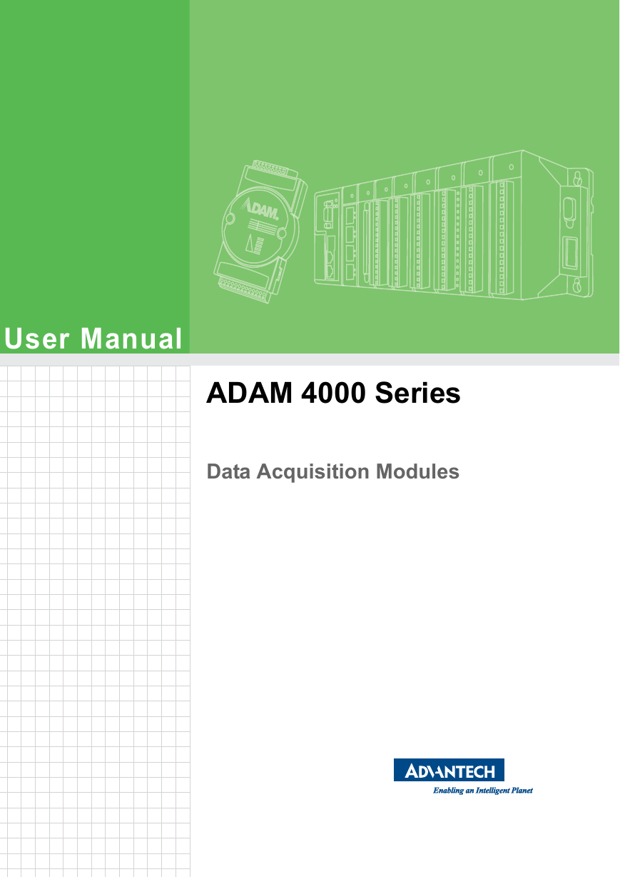
User Manual ADAM 4000 Series Data Acquisition Modules
Copyright The documentation and the software included with this product are copyrighted 2018 by Advantech Co., Ltd. All rights are reserved. Advantech Co., Ltd. reserves the right to make improvements in the products described in this manual at any time without notice. No part of this manual may be reproduced, copied, translated or transmitted in any form or by any means without the prior written permission of Advantech Co., Ltd. Information provided in this manual is intended to be accurate and reliable. How- ever, Advantech Co., Ltd. assumes no responsibility for its use, nor for any infringe- ments of the rights of third parties, which may result from its use. Acknowledgements ADAM is a trademark of Advantech Co., Ltd. IBM and PC are trademarks of International Business Machines Corporation. All other product names or trademarks are properties of their respective owners. Product Warranty (2 years) Advantech warrants to you, the original purchaser, that each of its products will be free from defects in materials and workmanship for two years from the date of pur- chase. This warranty does not apply to any products which have been repaired or altered by persons other than repair personnel authorized by Advantech, or which have been subject to misuse, abuse, accident or improper installation. Advantech assumes no liability under the terms of this warranty as a consequence of such events. Because of Advantech’s high quality-control standards and rigorous testing, most of our customers never need to use our repair service. If an Advantech product is defec- tive, it will be repaired or replaced at no charge during the warranty period. For out- of-warranty repairs, you will be billed according to the cost of replacement materials, service time and freight. Please consult your dealer for more details. If you think you have a defective product, follow these steps: 1. Collect all the information about the problem encountered. (For example, CPU speed, Advantech products used, other hardware and software used, etc.) Note anything abnormal and list any onscreen messages you get when the problem occurs. 2. Call your dealer and describe the problem. Please have your manual, product, 3. and any helpful information readily available. If your product is diagnosed as defective, obtain an RMA (return merchandize authorization) number from your dealer. This allows us to process your return more quickly. 4. Carefully pack the defective product, a fully-completed Repair and Replacement Order Card and a photocopy proof of purchase date (such as your sales receipt) in a shippable container. A product returned without proof of the purchase date is not eligible for warranty service. 5. Write the RMA number visibly on the outside of the package and ship it prepaid to your dealer. Part No. 2003A40007 Printed in Taiwan Edition 8 December 2018 ADAM-4000 Series User Manual ii
Declaration of Conformity CE The ADAM-4000 series developed by Advantech Co., Ltd. has passed the CE test for environmental specifications when operated within an industrial enclosure (ADAM- 4950-ENC). Therefore, in order to protect the ADAM modules from being damaged by ESD (Electric Static Discharge), we strongly recommend that the use of CE-com- pliant industrial enclosure products when using any ADAM module. Technical Support and Assistance 1. Visit the Advantech web site at www.advantech.com/support where you can find the latest information about the product. 2. Contact your distributor, sales representative, or Advantech's customer service center for technical support if you need additional assistance. Please have the following information ready before you call: – Product name and serial number – Description of your peripheral attachments – Description of your software (operating system, version, application software, etc.) – A complete description of the problem – The exact wording of any error messages iii ADAM-4000 Series User Manual
ADAM-4000 Series User Manual iv
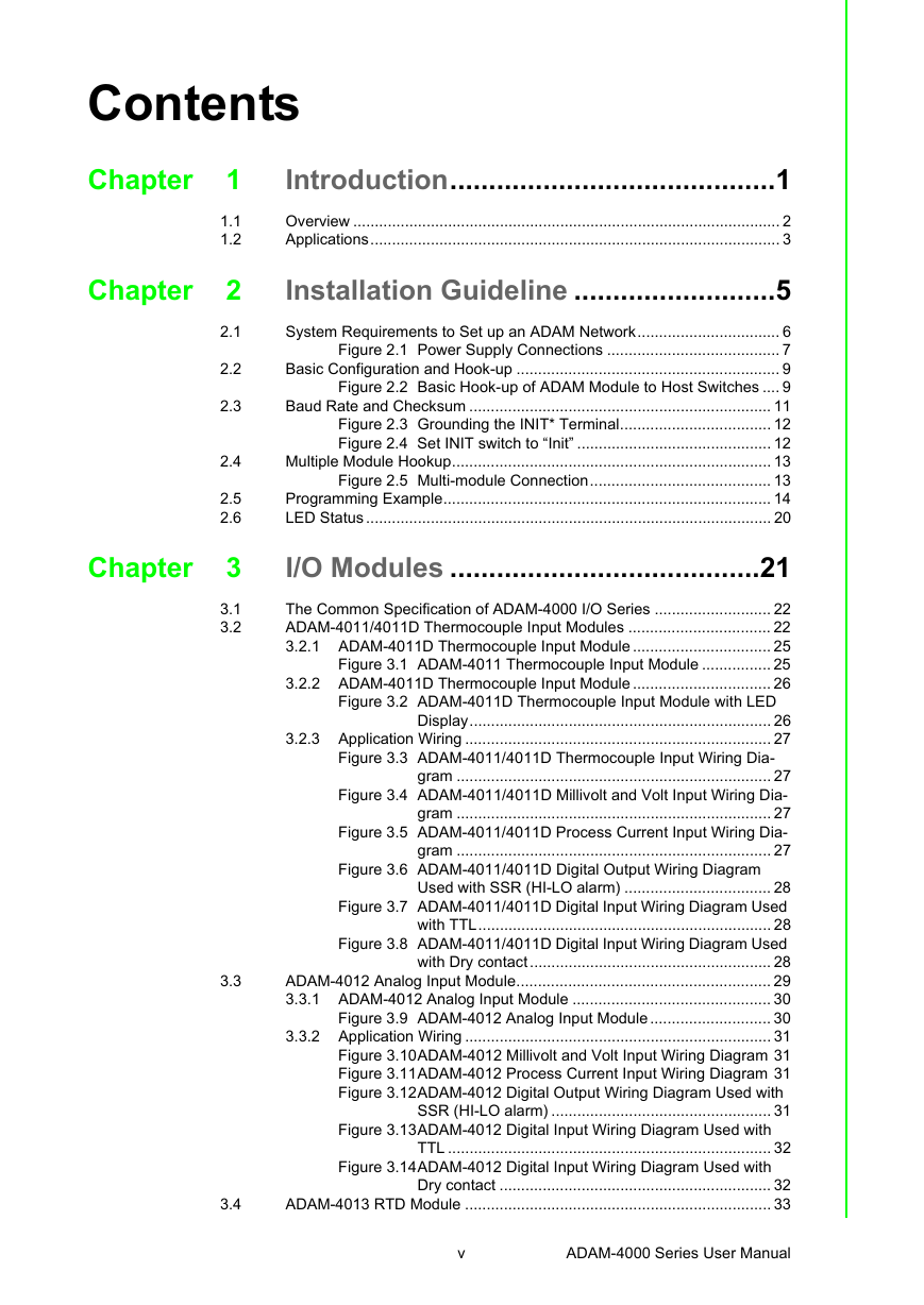
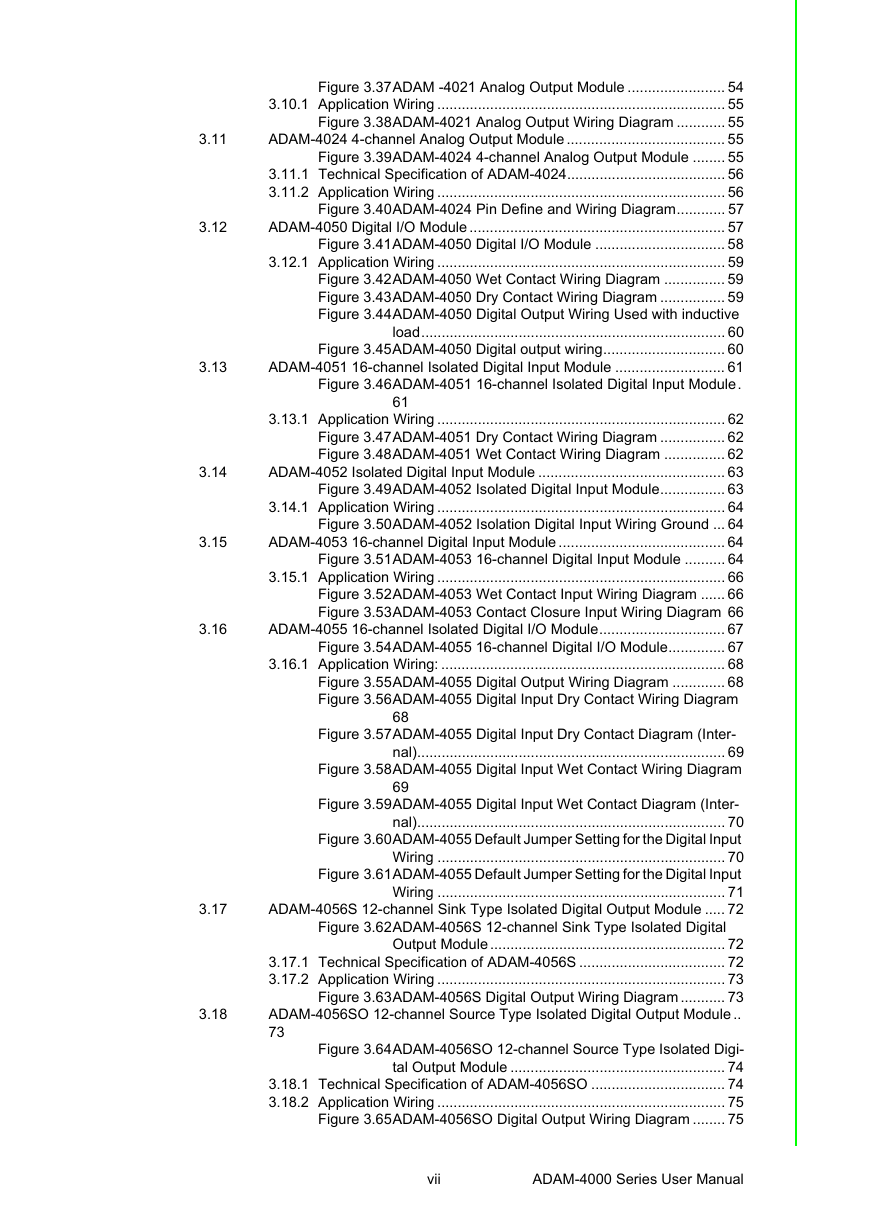
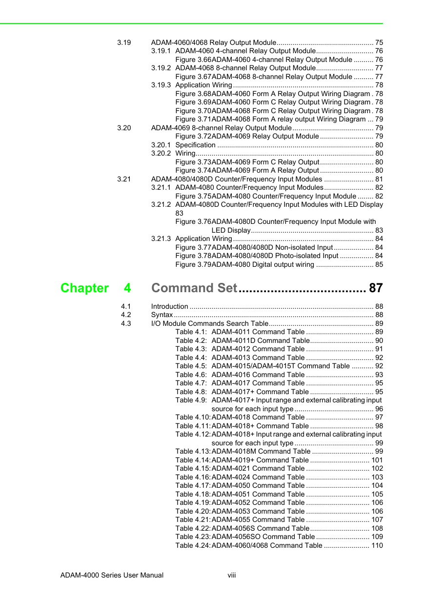
Contents Chapter Chapter Chapter 1 1.1 1.2 2 2.1 2.2 2.3 2.4 2.5 2.6 3 3.1 3.2 3.3 3.4 Introduction..........................................1 Overview ................................................................................................... 2 Applications............................................................................................... 3 Installation Guideline ..........................5 System Requirements to Set up an ADAM Network................................. 6 Figure 2.1 Power Supply Connections ........................................ 7 Basic Configuration and Hook-up ............................................................. 9 Figure 2.2 Basic Hook-up of ADAM Module to Host Switches .... 9 Baud Rate and Checksum ...................................................................... 11 Figure 2.3 Grounding the INIT* Terminal................................... 12 Figure 2.4 Set INIT switch to “Init” ............................................. 12 Multiple Module Hookup.......................................................................... 13 Figure 2.5 Multi-module Connection.......................................... 13 Programming Example............................................................................ 14 LED Status .............................................................................................. 20 I/O Modules ........................................21 The Common Specification of ADAM-4000 I/O Series ........................... 22 ADAM-4011/4011D Thermocouple Input Modules ................................. 22 3.2.1 ADAM-4011D Thermocouple Input Module ................................ 25 Figure 3.1 ADAM-4011 Thermocouple Input Module ................ 25 3.2.2 ADAM-4011D Thermocouple Input Module ................................ 26 Figure 3.2 ADAM-4011D Thermocouple Input Module with LED Display...................................................................... 26 3.2.3 Application Wiring ....................................................................... 27 Figure 3.3 ADAM-4011/4011D Thermocouple Input Wiring Dia- gram ......................................................................... 27 Figure 3.4 ADAM-4011/4011D Millivolt and Volt Input Wiring Dia- gram ......................................................................... 27 Figure 3.5 ADAM-4011/4011D Process Current Input Wiring Dia- gram ......................................................................... 27 Figure 3.6 ADAM-4011/4011D Digital Output Wiring Diagram Used with SSR (HI-LO alarm) .................................. 28 Figure 3.7 ADAM-4011/4011D Digital Input Wiring Diagram Used with TTL.................................................................... 28 Figure 3.8 ADAM-4011/4011D Digital Input Wiring Diagram Used with Dry contact........................................................ 28 ADAM-4012 Analog Input Module........................................................... 29 3.3.1 ADAM-4012 Analog Input Module .............................................. 30 Figure 3.9 ADAM-4012 Analog Input Module ............................ 30 3.3.2 Application Wiring ....................................................................... 31 Figure 3.10ADAM-4012 Millivolt and Volt Input Wiring Diagram 31 Figure 3.11ADAM-4012 Process Current Input Wiring Diagram 31 Figure 3.12ADAM-4012 Digital Output Wiring Diagram Used with SSR (HI-LO alarm) ................................................... 31 Figure 3.13ADAM-4012 Digital Input Wiring Diagram Used with TTL ........................................................................... 32 Figure 3.14ADAM-4012 Digital Input Wiring Diagram Used with Dry contact ............................................................... 32 ADAM-4013 RTD Module ....................................................................... 33 v ADAM-4000 Series User Manual
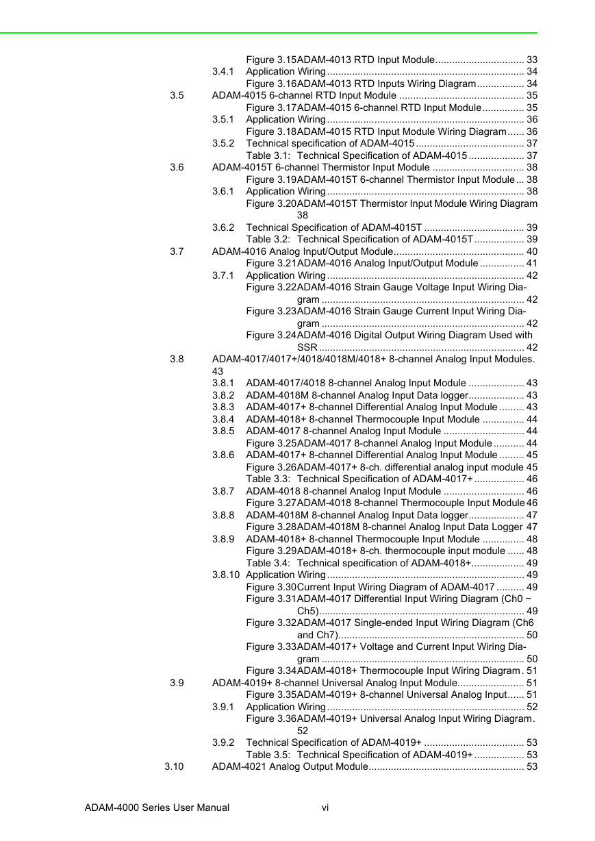
Figure 3.15ADAM-4013 RTD Input Module................................ 33 3.4.1 Application Wiring....................................................................... 34 Figure 3.16ADAM-4013 RTD Inputs Wiring Diagram................. 34 ADAM-4015 6-channel RTD Input Module ............................................. 35 Figure 3.17ADAM-4015 6-channel RTD Input Module............... 35 3.5.1 Application Wiring....................................................................... 36 Figure 3.18ADAM-4015 RTD Input Module Wiring Diagram...... 36 3.5.2 Technical specification of ADAM-4015....................................... 37 Table 3.1: Technical Specification of ADAM-4015 .................... 37 ADAM-4015T 6-channel Thermistor Input Module ................................. 38 Figure 3.19ADAM-4015T 6-channel Thermistor Input Module... 38 3.6.1 Application Wiring....................................................................... 38 Figure 3.20ADAM-4015T Thermistor Input Module Wiring Diagram 3.6.2 Technical Specification of ADAM-4015T .................................... 39 Table 3.2: Technical Specification of ADAM-4015T.................. 39 ADAM-4016 Analog Input/Output Module............................................... 40 Figure 3.21ADAM-4016 Analog Input/Output Module ................ 41 3.7.1 Application Wiring....................................................................... 42 Figure 3.22ADAM-4016 Strain Gauge Voltage Input Wiring Dia- gram ......................................................................... 42 38 Figure 3.23ADAM-4016 Strain Gauge Current Input Wiring Dia- gram ......................................................................... 42 Figure 3.24ADAM-4016 Digital Output Wiring Diagram Used with SSR .......................................................................... 42 ADAM-4017/4017+/4018/4018M/4018+ 8-channel Analog Input Modules. 43 3.8.1 ADAM-4017/4018 8-channel Analog Input Module .................... 43 3.8.2 ADAM-4018M 8-channel Analog Input Data logger.................... 43 3.8.3 ADAM-4017+ 8-channel Differential Analog Input Module ......... 43 3.8.4 ADAM-4018+ 8-channel Thermocouple Input Module ............... 44 3.8.5 ADAM-4017 8-channel Analog Input Module ............................. 44 Figure 3.25ADAM-4017 8-channel Analog Input Module ........... 44 3.8.6 ADAM-4017+ 8-channel Differential Analog Input Module ......... 45 Figure 3.26ADAM-4017+ 8-ch. differential analog input module 45 Table 3.3: Technical Specification of ADAM-4017+.................. 46 3.8.7 ADAM-4018 8-channel Analog Input Module ............................. 46 Figure 3.27ADAM-4018 8-channel Thermocouple Input Module 46 3.8.8 ADAM-4018M 8-channel Analog Input Data logger.................... 47 Figure 3.28ADAM-4018M 8-channel Analog Input Data Logger 47 3.8.9 ADAM-4018+ 8-channel Thermocouple Input Module ............... 48 Figure 3.29ADAM-4018+ 8-ch. thermocouple input module ...... 48 Table 3.4: Technical specification of ADAM-4018+................... 49 3.8.10 Application Wiring....................................................................... 49 Figure 3.30Current Input Wiring Diagram of ADAM-4017 .......... 49 Figure 3.31ADAM-4017 Differential Input Wiring Diagram (Ch0 ~ Ch5).......................................................................... 49 Figure 3.32ADAM-4017 Single-ended Input Wiring Diagram (Ch6 and Ch7)................................................................... 50 Figure 3.33ADAM-4017+ Voltage and Current Input Wiring Dia- gram ......................................................................... 50 Figure 3.34ADAM-4018+ Thermocouple Input Wiring Diagram. 51 ADAM-4019+ 8-channel Universal Analog Input Module........................ 51 Figure 3.35ADAM-4019+ 8-channel Universal Analog Input...... 51 3.9.1 Application Wiring....................................................................... 52 Figure 3.36ADAM-4019+ Universal Analog Input Wiring Diagram. 3.9.2 Technical Specification of ADAM-4019+ .................................... 53 Table 3.5: Technical Specification of ADAM-4019+.................. 53 ADAM-4021 Analog Output Module........................................................ 53 52 3.5 3.6 3.7 3.8 3.9 3.10 ADAM-4000 Series User Manual vi
3.11 3.12 3.13 3.14 3.15 3.16 3.17 3.18 Figure 3.37ADAM -4021 Analog Output Module ........................ 54 3.10.1 Application Wiring ....................................................................... 55 Figure 3.38ADAM-4021 Analog Output Wiring Diagram ............ 55 ADAM-4024 4-channel Analog Output Module ....................................... 55 Figure 3.39ADAM-4024 4-channel Analog Output Module ........ 55 3.11.1 Technical Specification of ADAM-4024....................................... 56 3.11.2 Application Wiring ....................................................................... 56 Figure 3.40ADAM-4024 Pin Define and Wiring Diagram............ 57 ADAM-4050 Digital I/O Module ............................................................... 57 Figure 3.41ADAM-4050 Digital I/O Module ................................ 58 3.12.1 Application Wiring ....................................................................... 59 Figure 3.42ADAM-4050 Wet Contact Wiring Diagram ............... 59 Figure 3.43ADAM-4050 Dry Contact Wiring Diagram ................ 59 Figure 3.44ADAM-4050 Digital Output Wiring Used with inductive load........................................................................... 60 Figure 3.45ADAM-4050 Digital output wiring.............................. 60 ADAM-4051 16-channel Isolated Digital Input Module ........................... 61 Figure 3.46ADAM-4051 16-channel Isolated Digital Input Module. 3.13.1 Application Wiring ....................................................................... 62 Figure 3.47ADAM-4051 Dry Contact Wiring Diagram ................ 62 Figure 3.48ADAM-4051 Wet Contact Wiring Diagram ............... 62 ADAM-4052 Isolated Digital Input Module .............................................. 63 Figure 3.49ADAM-4052 Isolated Digital Input Module................ 63 3.14.1 Application Wiring ....................................................................... 64 Figure 3.50ADAM-4052 Isolation Digital Input Wiring Ground ... 64 ADAM-4053 16-channel Digital Input Module ......................................... 64 Figure 3.51ADAM-4053 16-channel Digital Input Module .......... 64 3.15.1 Application Wiring ....................................................................... 66 Figure 3.52ADAM-4053 Wet Contact Input Wiring Diagram ...... 66 Figure 3.53ADAM-4053 Contact Closure Input Wiring Diagram 66 ADAM-4055 16-channel Isolated Digital I/O Module............................... 67 Figure 3.54ADAM-4055 16-channel Digital I/O Module.............. 67 3.16.1 Application Wiring: ...................................................................... 68 Figure 3.55ADAM-4055 Digital Output Wiring Diagram ............. 68 Figure 3.56ADAM-4055 Digital Input Dry Contact Wiring Diagram 61 68 69 Figure 3.57ADAM-4055 Digital Input Dry Contact Diagram (Inter- nal)............................................................................ 69 Figure 3.58ADAM-4055 Digital Input Wet Contact Wiring Diagram Figure 3.59ADAM-4055 Digital Input Wet Contact Diagram (Inter- nal)............................................................................ 70 Figure 3.60ADAM-4055 Default Jumper Setting for the Digital Input Wiring ....................................................................... 70 Figure 3.61ADAM-4055 Default Jumper Setting for the Digital Input Wiring ....................................................................... 71 ADAM-4056S 12-channel Sink Type Isolated Digital Output Module ..... 72 Figure 3.62ADAM-4056S 12-channel Sink Type Isolated Digital Output Module .......................................................... 72 3.17.1 Technical Specification of ADAM-4056S .................................... 72 3.17.2 Application Wiring ....................................................................... 73 Figure 3.63ADAM-4056S Digital Output Wiring Diagram ........... 73 ADAM-4056SO 12-channel Source Type Isolated Digital Output Module .. 73 Figure 3.64ADAM-4056SO 12-channel Source Type Isolated Digi- tal Output Module ..................................................... 74 3.18.1 Technical Specification of ADAM-4056SO ................................. 74 3.18.2 Application Wiring ....................................................................... 75 Figure 3.65ADAM-4056SO Digital Output Wiring Diagram ........ 75 vii ADAM-4000 Series User Manual
3.19 3.20 3.21 4 4.1 4.2 4.3 Chapter ADAM-4060/4068 Relay Output Module................................................. 75 3.19.1 ADAM-4060 4-channel Relay Output Module............................. 76 Figure 3.66ADAM-4060 4-channel Relay Output Module .......... 76 3.19.2 ADAM-4068 8-channel Relay Output Module............................. 77 Figure 3.67ADAM-4068 8-channel Relay Output Module .......... 77 3.19.3 Application Wiring....................................................................... 78 Figure 3.68ADAM-4060 Form A Relay Output Wiring Diagram . 78 Figure 3.69ADAM-4060 Form C Relay Output Wiring Diagram . 78 Figure 3.70ADAM-4068 Form C Relay Output Wiring Diagram . 78 Figure 3.71ADAM-4068 Form A relay output Wiring Diagram ... 79 ADAM-4069 8-channel Relay Output Module......................................... 79 Figure 3.72ADAM-4069 Relay Output Module ........................... 79 3.20.1 Specification ............................................................................... 80 3.20.2 Wiring.......................................................................................... 80 Figure 3.73ADAM-4069 Form C Relay Output........................... 80 Figure 3.74ADAM-4069 Form A Relay Output ........................... 80 ADAM-4080/4080D Counter/Frequency Input Modules ......................... 81 3.21.1 ADAM-4080 Counter/Frequency Input Modules......................... 82 Figure 3.75ADAM-4080 Counter/Frequency Input Module ........ 82 3.21.2 ADAM-4080D Counter/Frequency Input Modules with LED Display 83 Figure 3.76ADAM-4080D Counter/Frequency Input Module with LED Display.............................................................. 83 3.21.3 Application Wiring....................................................................... 84 Figure 3.77ADAM-4080/4080D Non-isolated Input .................... 84 Figure 3.78ADAM-4080/4080D Photo-isolated Input ................. 84 Figure 3.79ADAM-4080 Digital output wiring ............................. 85 Command Set.................................... 87 Introduction ............................................................................................. 88 Syntax..................................................................................................... 88 I/O Module Commands Search Table..................................................... 89 Table 4.1: ADAM-4011 Command Table .................................. 89 Table 4.2: ADAM-4011D Command Table................................ 90 Table 4.3: ADAM-4012 Command Table .................................. 91 Table 4.4: ADAM-4013 Command Table .................................. 92 Table 4.5: ADAM-4015/ADAM-4015T Command Table ........... 92 Table 4.6: ADAM-4016 Command Table .................................. 93 Table 4.7: ADAM-4017 Command Table .................................. 95 Table 4.8: ADAM-4017+ Command Table ................................ 95 Table 4.9: ADAM-4017+ Input range and external calibrating input source for each input type ........................................ 96 Table 4.10:ADAM-4018 Command Table .................................. 97 Table 4.11:ADAM-4018+ Command Table ................................ 98 Table 4.12:ADAM-4018+ Input range and external calibrating input source for each input type ........................................ 99 Table 4.13:ADAM-4018M Command Table ............................... 99 Table 4.14:ADAM-4019+ Command Table .............................. 101 Table 4.15:ADAM-4021 Command Table ................................ 102 Table 4.16:ADAM-4024 Command Table ................................ 103 Table 4.17:ADAM-4050 Command Table ................................ 104 Table 4.18:ADAM-4051 Command Table ................................ 105 Table 4.19:ADAM-4052 Command Table ................................ 106 Table 4.20:ADAM-4053 Command Table ................................ 106 Table 4.21:ADAM-4055 Command Table ................................ 107 Table 4.22:ADAM-4056S Command Table.............................. 108 Table 4.23:ADAM-4056SO Command Table ........................... 109 Table 4.24:ADAM-4060/4068 Command Table ....................... 110 ADAM-4000 Series User Manual viii
分享到:
收藏