Transportation Research Part D 37 (2015) 79–96
Contents lists available at ScienceDirect
Transportation Research Part D
j o u r n a l h o m e p a g e : w w w . e l s e v i e r . c o m / l o c a t e / t r d
Development a new power management strategy for power
split hybrid electric vehicles
Morteza Montazeri-Gh, Mehdi Mahmoodi-k
⇑
Systems Simulation and Control Laboratory, School of Mechanical Engineering, Iran University of Science and Technology, Tehran, P.O. Box 16846-13114, Iran
a r t i c l e
i n f o
a b s t r a c t
Article history:
Available online 16 May 2015
Keywords:
Power-split hybrid vehicle
Energy management
Fuzzy logic controller
State of charge
Pollution emissions and fuel consumption
Reduction of greenhouse gas emission and fuel consumption as one of the main goals of
automotive industry leading to the development hybrid vehicles. The objective of this
paper is to investigate the energy management system and control strategies effect on fuel
consumption, air pollution and performance of hybrid vehicles in various driving cycles. In
order to simulate the hybrid vehicle, the combined feedback–feedforward architecture of
the power-split hybrid electric vehicle based on Toyota Prius configuration is modeled,
together with necessary dynamic features of subsystem or components in ADVISOR.
Multi input fuzzy logic controller developed for energy management controller to improve
the fuel economy of a power-split hybrid electric vehicle with contrast to conventional
Toyota Prius Hybrid rule-based controller. Then, effects of battery’s initial state of charge,
driving cycles and road grade investigated on hybrid vehicle performance to evaluate fuel
consumption and pollution emissions. The simulation results represent the effectiveness
and applicability of the proposed control strategy. Also, results indicate that proposed con-
troller is reduced fuel consumption in real and modal driving cycles about 21% and 6%
respectively.
Ó 2015 Elsevier Ltd. All rights reserved.
Introduction
Nowadays due to the transportation sector has been one of the top contributors in increasing air pollution and fuel con-
sumption, a significant interest in hybrid electric vehicle (HEV) has arisen globally to reduce fuel consumption and pollution
emissions. According to the U.S. Department of Energy (USDE), about 15% of the total fuel energy is consumed to run a car
and its other accessories. The main concern in vehicle emissions is CO2 which is related to fuel consumption linearly (Chau
and Chan, 2007). In order to overcome these problems, HEVs incorporates two power drives including an internal combus-
tion engine (ICE) and an electric motor (EM) which results in optimal energy management. HEV’s reduce Green House Gas
(GHG) emissions, and displace petroleum energy by utilizing both powertrains to increase vehicle efficiency. The conven-
tional vehicle engine is typically sized to meet high power demands, while the hybrid electric vehicle powertrain is sized
Abbreviations: HEV, hybrid electric vehicle; USDE, U.S. Department of Energy; ICE, internal combustion engine; EM, electric motor; FLC, Fuzzy Logic
Controller; FCHV, fuel cell hybrid vehicle; SOC, state of charge; MPC, Model Predictive Control; PHEV, plug-in hybrid electric vehicle; NEDC, New European
Driving Cycle; GHG, Green House Gas; THS, Toyota Hybrid System; EVT, electronically variable transmission; DP, dynamic programming; EMS, energy
management strategy; QP, quadratic programming; MG, motor/generator; UDDS, Urban Dynamometer Driving Schedule; FTP-75, Federal Test Procedure;
Teh-car, Tehran Car.
⇑ Corresponding author.
E-mail address: M_mahmoodi_k@iust.ac.ir (M. Mahmoodi-k).
http://dx.doi.org/10.1016/j.trd.2015.04.024
1361-9209/Ó 2015 Elsevier Ltd. All rights reserved.
�
80
M. Montazeri-Gh, M. Mahmoodi-k / Transportation Research Part D 37 (2015) 79–96
to enable engine start/stops, regenerate during braking. In order to make more significant reductions in pollution emissions
and petroleum energy usage vehicle architectures also need to be considered.
There are many different hybrid configurations currently proposed by vehicle manufacturers (Fan, 2007; He et al., 2012;
Zhang, 2011, Liu, 2013; Murphey et al., 2013), most configurations can be categorized into three hybrid systems: Series,
Parallel and Power-split. In this paper, power-split hybrid vehicle is considered, which it combines the advantages of series
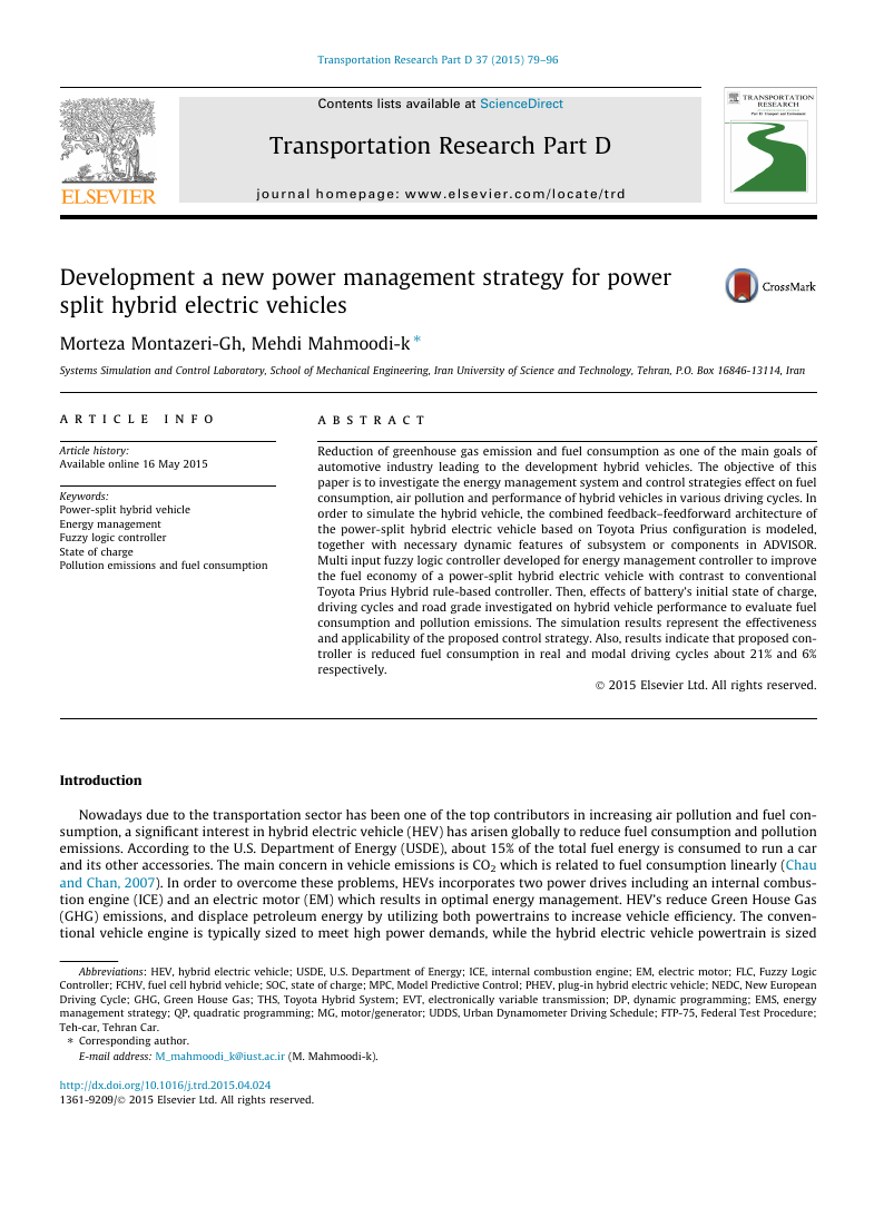
and parallel hybrids by utilizing two electric machines and a combustion engine as shown in Fig. 1.
With the potential for achieving higher fuel economy, power-split HEV has been seen as one of the hybrid powertrain
architecture to improve fuel economy when their power-management algorithms are properly designed. Most of the atten-
tion has been given to designing energy management control systems in power-split HEVs which is responsible for selecting
operating points of the subsystems to achieve better vehicle fuel efficiency (He et al., 2012; Zhang, 2011; Liu, 2013; Murphey
et al., 2013; Zheng and Mi, 2009).
The power-split hybrid configuration can switch between the parallel and series which, according to driving condition the
high efficiency range of each one is selected. Depending on the situation, both power sources (electrical and mechanical
paths) can also be used simultaneously to achieve the maximum power output efficiency. The biggest advantage of the plan-
etary gear mechanisms is that high rotational ratios can be produced by using small number of relatively small dimensioned
gear systems. Also the input and output shafts are coaxial so the mechanism is extremely well assembled (Liu, 2007; Macor
and Rossetti, 2013). Other advantages are eliminated radial loads, working silently and the facility of using planets in steps.
Power split powertrains can be divided into single (Toyota Hybrid System (THS)) and multi-mode systems (Allison Hybrid
System) which uses two or more planetary gears and has two electronically variable transmission (EVT) modes. Trade-off
between multi-mode powertrain complexity and fuel consumption has been performed in Kim et al., 2010 to provide a
detailed review of the benefits and drawbacks of the single and two-mode systems, the three-mode and four-mode vehicles.
It was found that the multi-mode system has more fuel economy advantage during the high-speed cycle due to the relatively
higher system efficiency. In this paper due to complexity, high cost and additional weight of multi-mode systems, single
mode configuration of Toyota Prius has been considered.
One of the most significant factors in the performance of hybrid vehicles are control strategies, which play an important
role in improving energy management of HEVs. Different strategies has been used in previous studies which mainly are clas-
sified into rule based and optimization approaches (Tie and Tan, 2013). Majority of the proposed solutions for the power
management control logic can be classified under two types: rule-based approach and optimization-based approach.
Rule-based control strategies consist of deterministic and fuzzy logic rule-based methods, while optimization-based
approaches typically utilized global optimization when determining the control strategy (Salmasi, 2007). In Zahabi et al.
(2014) the effect of different factors on fuel efficiency including road driving conditions (link type, city size), temperature,
speed, cold-starts and eco-driving training is compared for HEVs and conventional gasoline vehicles. Results demonstrated
that winter time significantly increased the fuel consumption of HEVs.
Delprat et al. (2004) and Mansour and Clodic (2012) proposed a global optimal strategy based on dynamic programming
(DP) methods for parallel HEV and parallel-series HEV, respectively. An overview of the controllers was given in Wirasingha
and Emadi (2011), and an analysis on which strategy is more suitable to maximize HEV performance in different drive cycle
conditions was provided. They presented a new classification for HEV control strategies based on the operation of the vehicle
and verified through simulation results. Kim et al. (2009) proposed nonlinear model predictive control algorithm based on
DP procedure for the vehicle control system to maximize fuel economy while satisfying constraints on battery state of
charge, relative position and vehicle performance. One of the disadvantages of this control is approximation/transformation
that may not be applicable in complicated drive train system. Power-split hybrid vehicles have two degrees of freedom in the
Fig. 1. Power-split hybrid vehicle modeling.
�
M. Montazeri-Gh, M. Mahmoodi-k / Transportation Research Part D 37 (2015) 79–96
81
control strategy. So, it’s difficult to apply the DP algorithm in these kinds of vehicles and it is probably cannot converge to
exact optimal solution. Also, it is not suitable for real-time control (Tie and Tan, 2013).
Previous studies (Jalil et al., 2002; Montazeri et al., 2006; Baumann, 1997; Kono, 1998; Martínez et al., 2013, 2012),
already indicated that Fuzzy Logic Controller (FLC) is very suitable for HEV control. It is an appropriate method for real-
izing an optimal tradeoff between the efficiencies of all components of the HEV. A FLC with Mamdani implication is used
in this paper, which is in the group of rule-based controllers. The FLC of the hybrid powertrain does not rely on a precise
mathematic model and has preferably robust properties. Wu et al. (2012) presented a fuzzy energy management strategy
(EMS) based on driving cycle recognition to improve the fuel economy of a parallel hybrid electric vehicle by considering
the effect of the driving cycle on the EMS. Ning et al. (2010) constructed a comprehensive simulation model for the fuel
cell hybrid vehicle (FCHV) power train in parallel with a power control strategy that uses a logic threshold approach
implemented with a hybrid control unit. The proposed optimal configuration model has six possible operating modes
and power flows between each subsystem according to the particular conditions identified by the system operation. It
provides the capability of achieving the requested drive power while also meeting the vehicle driving schedule and
recovery needs of the state of charge (SOC) battery, with lower fuel consumption levels. In Xiong et al. (2009), two sep-
arated controllers using fuzzy logic called Mode Decision and Parallel-driving Energy Management has been employed to
fulfill switching between the series mode and the parallel mode as well as the instantaneous power distribution. By con-
sidering the effect of the driving cycle on the EMS, a fuzzy EMS based on driving cycle recognition has been proposed to
improve the fuel economy of a parallel hybrid electric vehicle. The EMS was composed of driving cycle recognition and a
fuzzy torque distribution controller, which optimized simultaneously by using particle swarm optimization (Wu et al.,
2012).
A Model Predictive Control (MPC) strategy is developed to solve the optimal energy management problem of power-split
hybrid electric vehicles. A power-split hybrid combines the advantages of series and parallel hybrids by utilizing two electric
machines and a combustion engine. The proposed algorithm is causal and has the potential for real-time implementation
(Borhan et al., 2009). Chen et al. (2014) proposed an online and intelligent energy management controller to improve the
fuel economy of a power-split plug-in hybrid electric vehicle (PHEV) introduce. The optimal battery current when the engine
is on is calculated using quadratic programming (QP) method. The proposed algorithm can control the battery current effec-
tively, which makes the engine work more efficiently and thus reduce the fuel-consumption.
In this paper multi input FLC developed for energy management of power-split configuration, which is adaptive to various
driving cycles. Then, the efficiency of proposed controller in terms of fuel consumption and pollution emissions compared
with rule-based controller of Toyota Prius power-split hybrid vehicle.
Vehicle model
In order to develop longitudinal vehicle dynamics for power-split hybrid vehicle configuration, a force balancing along the
vehicle longitudinal axis yields:
m
du
dt
¼ Te
Rtire
� 1
2
qAf Cdu2 � mg sin h � lmg cos h
ð1Þ
where m, u and Te are vehicle mass, longitudinal velocity and engine torque respectively. Af and Rtire are frontal area of the
vehicle and the wheel radius, l is the friction coefficient, Cd and q are the drag coefficient and air density, h is the road grade
and g is gravitational acceleration.
In the next step, powertrain and planetary gear sets dynamics are extracted for power-split hybrid vehicle to achieve its
state space form.
Dynamic modeling of power-split hybrid vehicles
Power-split hybrid vehicle implements planetary gear set instead of transmission to link the engine with the final drive.
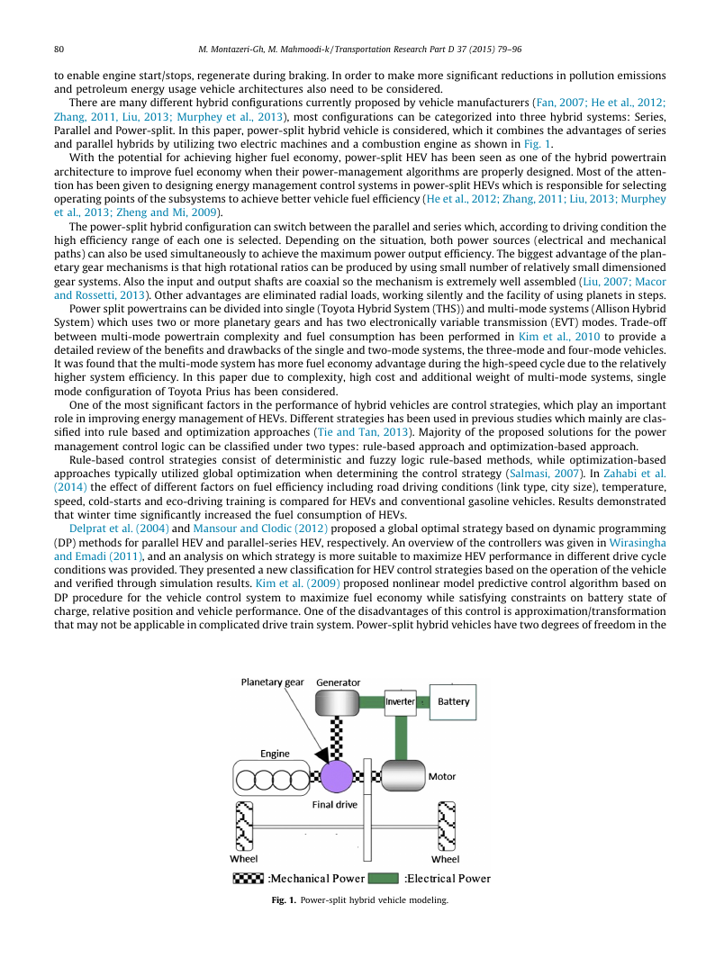
Fig. 2 shows a powertrain design example of the single-mode power-split hybrid system. A single planetary gear set serves as
a power-split device that transfers the engine power to the vehicle through a mechanical (parallel) and an electrical (series)
paths. The engine power through the mechanical path goes directly to the final drive of the vehicle. The rest of the engine
power goes to the motor/generator 1 (MG1), where it is transformed into electricity. This power is then either stored in the
battery or send to the motor/generator 2 (MG2) by a controlled power bus.
Planetary gear is the main part of power-split powertrain system. As shown in Fig. 2 it consists of the three basic
components: Sun gear, Planet carrier, Ring. The overall gear ratio of a simple planetary gear set can be reliably calcu-
lated using the following two equations,
representing the sun–planet and planet–ring kinematic interactions
respectively:
Rsxs þ Rpxp � ðRs þ RpÞxc ¼ 0
Rrxr � Rpxp � ðRr � RpÞxc ¼ 0
ð2Þ
ð3Þ
�
82
M. Montazeri-Gh, M. Mahmoodi-k / Transportation Research Part D 37 (2015) 79–96
Fig. 2. Planetary gear set operation mechanism (http://www.carbibles.com/images/planetarygearset.jpg).
where R and x are radius and rotational speeds of gears respectively. Indexes r, s, p and c represent ring, sun, planet and
carrier gears.
The fundamental formula of the planetary gear train with a rotating carrier is obtained by recognizing that this formula
remains true if the angular velocities of the sun, planet and annular gears are computed relative to the carrier angular veloc-
ity. This becomes,
¼ xs � xc
xc � xr
Rr
Rs
ð4Þ
Each of the speed ratios available to a simple planetary gear train can be obtained by using clutches to hold and release the
carrier, sun or annular gears as needed.
The vehicle longitudinal components includes engine, motor, generator, power-split, final drive and wheels. In the
power-split system, planetary gear sets in a way that, the engine is connected to planet carrier as an input. Generator
and motor are linked with sun and ring gears respectively. Also, the ring gear connected to the final drive is considered
as the output. It is assumed that all powertrain components are rigid and the power loss in the final transmission can be
neglected with respect to other sources of power losses. So, the equation of motion for components described as:
ð5Þ
ð6Þ
Ieae ¼ Te � FðRs þ RrÞ
Imam ¼ Tm þ FRr � Td þ Tb
Igag ¼ Tg þ FRs
N
ð7Þ
where I and T are the inertia and torque. Indexes e, m and g represent engine, motor and generator respectively. Rs and Rr are
the radius of the sun and ring gears. N, F and a indicate final drive ratio, interaction force between different parts of
power-split and the rotational acceleration, Td and Tb are the drive shaft and brake torques respectively.
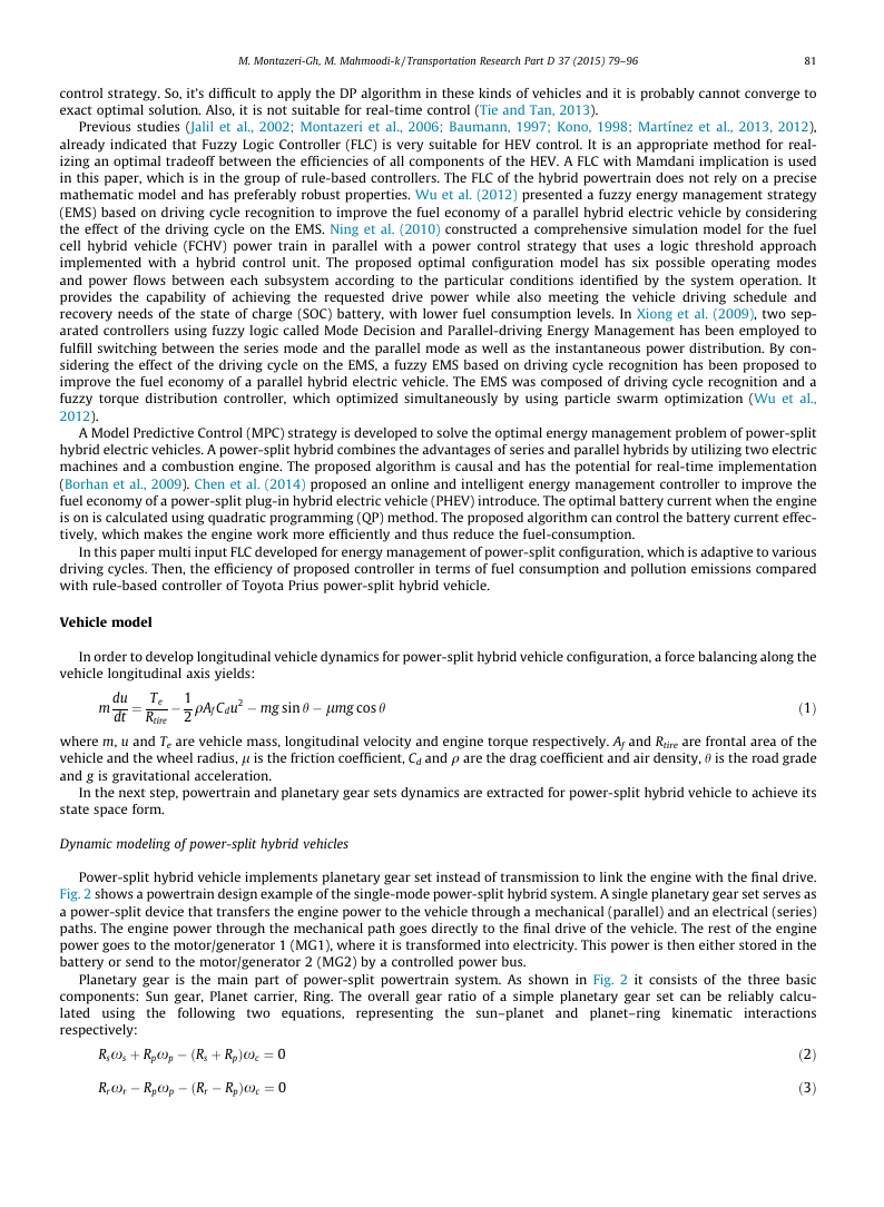
Fig. 3 shows a planetary gear and its equivalent lever diagram (Zhang et al., 2012). The three nodes in the lever diagram
represent the ring gear, carrier, and sun gear of the planetary gear, and each node can be connected to one or more power-
train elements.
By using the lever diagram presented, system equations of motion for planetary gear can be derived when neglecting the
inertias of the mass of the pinion gears, are given by
Irar ¼ FRr � Tr
ð8Þ
Fig. 3. Lever diagram of planetary gear set.
�
M. Montazeri-Gh, M. Mahmoodi-k / Transportation Research Part D 37 (2015) 79–96
83
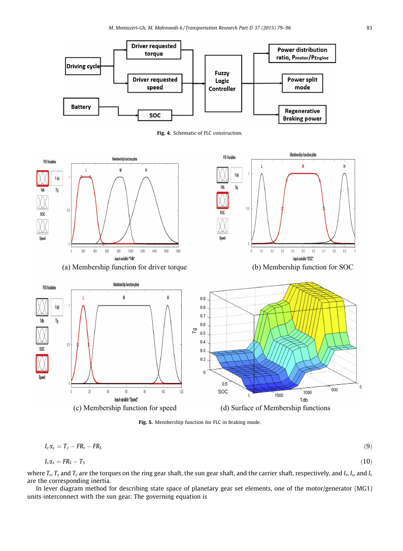
Fig. 4. Schematic of FLC construction.
(a) Membership function for driver torque
(b) Membership function for SOC
(c) Membership function for speed
(d) Surface of Membership functions
Fig. 5. Membership function for FLC in braking mode.
Icac ¼ Tc � FRr � FRS
Isas ¼ FRS � TS
ð9Þ
ð10Þ
where Tr, Ts and Tc are the torques on the ring gear shaft, the sun gear shaft, and the carrier shaft, respectively, and Ir, Is, and Ic
are the corresponding inertia.
In lever diagram method for describing state space of planetary gear set elements, one of the motor/generator (MG1)
units interconnect with the sun gear. The governing equation is
�
84
M. Montazeri-Gh, M. Mahmoodi-k / Transportation Research Part D 37 (2015) 79–96
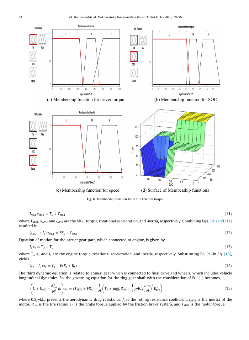
(a) Membership function for driver torque
(b) Membership function for SOC
(c) Membership function for speed
(d) Surface of Membership functions
Fig. 6. Membership function for FLC in traction torque.
IMG1aMG1 ¼ TS þ TMG1
ð11Þ
where TMG1, aMG1 and IMG1 are the MG1 torque, rotational acceleration, and inertia, respectively. Combining Eqs. (10) and (11)
resulted in
ðIMG1 þ ISÞaMG1 ¼ FRS þ TMG1
ð12Þ
Equation of motion for the carrier gear part, which connected to engine, is given by
Ieae ¼ Te � TC
ð13Þ
where Te, ae and Ie are the engine torque, rotational acceleration, and inertia, respectively. Substituting Eq. (9) in Eq. (13),
yields
ð14Þ
The third dynamic equation is related to annual gear which is connected to final drive and wheels, which includes vehicle
longitudinal dynamics. So, the governing equation for the ring gear shaft with the consideration of Eq. (1) becomes,
ðIe þ ICÞae ¼ Te � FðRS þ RrÞ
Ir þ IMG2 þ R2
!
N2 m
tire
ar ¼ ðTMG2 þ FRrÞ � 1
N
�
Tb þ mgfrRtire þ 1
2
�
�
�
xr
N
qACd
2
R3
tire
ð15Þ
where 0.5qAfCd presents the aerodynamic drag resistance, fr is the rolling resistance coefficient, IMG2 is the inertia of the
motor, Rtire is the tire radius, Tb is the brake torque applied by the friction brake system, and TMG2 is the motor torque.
�
M. Montazeri-Gh, M. Mahmoodi-k / Transportation Research Part D 37 (2015) 79–96
85
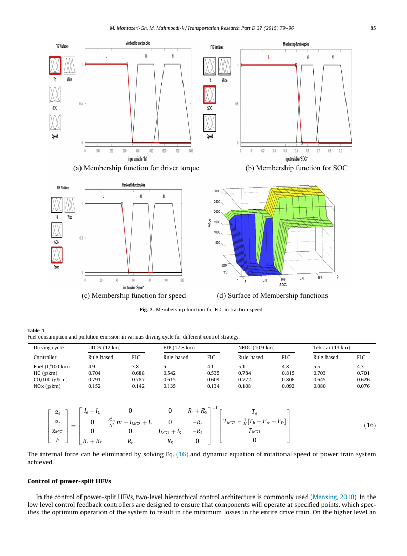
(a) Membership function for driver torque
(b) Membership function for SOC
(c) Membership function for speed
(d) Surface of Membership functions
Fig. 7. Membership function for FLC in traction speed.
Table 1
Fuel consumption and pollution emission in various driving cycle for different control strategy.
Driving cycle
UDDS (12 km)
FTP (17.8 km)
NEDC (10.9 km)
Teh-car (13 km)
Controller
Rule-based
Rule-based
FLC
Rule-based
FLC
Rule-based
Fuel (L/100 km)
HC (g/km)
CO/100 (g/km)
NOx (g/km)
2
6664
ae
ar
aMG1
F
4.9
0.704
0.791
0.152
Ie þ IC
0
0
Rr þ RS
2
66664
3
7775 ¼
FLC
3.8
0.688
0.787
0.142
0
R2
tire
N2 m þ IMG2 þ Ir
0
Rr
4.1
0.535
0.609
0.134
�1
2
6664
5
0.542
0.615
0.135
0
0
IMG1 þ IS
RS
Rr þ RS
�Rr
�RS
0
3
77775
5.1
0.784
0.772
0.108
5.5
0.703
0.645
0.080
4.8
0.815
0.806
0.092
3
7775
TMG2 � 1
N ½Tb þ Frr þ FD
TMG1
Te
0
FLC
4.3
0.701
0.626
0.076
ð16Þ
The internal force can be eliminated by solving Eq. (16) and dynamic equation of rotational speed of power train system
achieved.
Control of power-split HEVs
In the control of power-split HEVs, two-level hierarchical control architecture is commonly used (Mensing, 2010). In the
low level control feedback controllers are designed to ensure that components will operate at specified points, which spec-
ifies the optimum operation of the system to result in the minimum losses in the entire drive train. On the higher level an
�
86
M. Montazeri-Gh, M. Mahmoodi-k / Transportation Research Part D 37 (2015) 79–96
q
r
t
_
e
k
a
r
b
_
c
f
a
_
t
u
o
_
q
r
t
_
c
f
120
100
80
60
40
20
0
-20
-40
0
100
50
0
-50
0
Optimized Fuzzy
Prius-Rulebased
Optimized Fuzzy
Prius-Rullbased
0.7
0.65
0.6
0.55
0.5
i
t
s
h
_
c
o
s
_
s
s
e
200
400
600
time (s)
800
1000
1200
0.45
0
200
400
600
time (s)
800
1000
1200
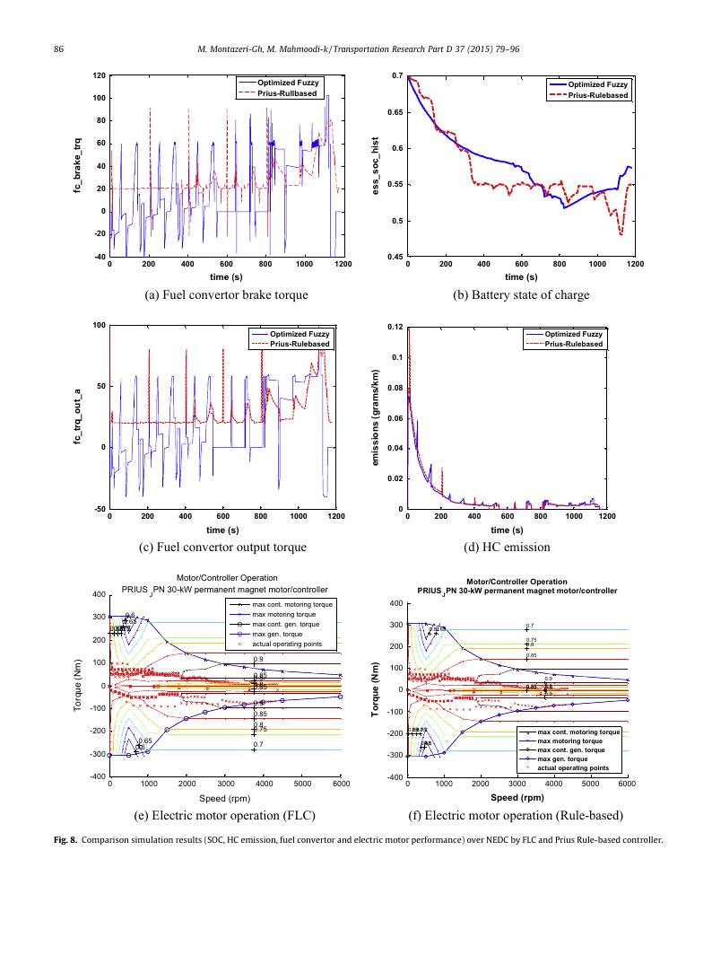
(a) Fuel convertor brake torque
(b) Battery state of charge
Optimized Fuzzy
Prius-Rulebased
200
400
600
800
1000
1200
time (s)
(c) Fuel convertor output torque
0.12
0.1
0.08
0.06
0.04
0.02
0
0
Optimized Fuzzy
Prius-Rulebased
200
400
600
800
1000
1200
time (s)
(d) HC emission
Motor/Controller Operation
PRIUSJPN 30-kW permanent magnet motor/controller
)
m
k
/
s
m
a
r
g
(
s
n
o
i
s
s
i
m
e
)
m
N
(
e
u
q
r
o
T
Motor/Controller Operation
PRIUS JPN 30-kW permanent magnet motor/controller
max cont. motoring torque
max motoring torque
max cont. gen. torque
max gen. torque
actual operating points
0.6
0.65
0.85
0.8
0.75
0.7
0.9
0.85
0.8
0.8
0.85
0.9
0.85
0.8
0.75
0.7
0.65
0.6
400
300
200
100
0
-100
-200
-300
)
m
N
(
e
u
q
r
o
T
400
300
200
100
0
-100
-200
-300
0.6
0.65
0.8
0.85
0.7
0.75
0.6
0.65
0.7
0.75
0.8
0.85
0.850.85
0.9
0.80.8
0.9
max cont. motoring torque
max motoring torque
max cont. gen. torque
max gen. torque
actual operating points
-400
0
1000
2000
3000
4000
5000
6000
-400
0
Speed (rpm)
1000
2000
3000
4000
5000
6000
Speed (rpm)
(e) Electric motor operation (FLC)
(f) Electric motor operation (Rule-based)
Fig. 8. Comparison simulation results (SOC, HC emission, fuel convertor and electric motor performance) over NEDC by FLC and Prius Rule-based controller.
�


 2023年江西萍乡中考道德与法治真题及答案.doc
 2012年重庆南川中考生物真题及答案.doc
 2013年江西师范大学地理学综合及文艺理论基础考研真题.doc
 2020年四川甘孜小升初语文真题及答案I卷.doc
 2020年注册岩土工程师专业基础考试真题及答案.doc
 2023-2024学年福建省厦门市九年级上学期数学月考试题及答案.doc
 2021-2022学年辽宁省沈阳市大东区九年级上学期语文期末试题及答案.doc
 2022-2023学年北京东城区初三第一学期物理期末试卷及答案.doc
 2018上半年江西教师资格初中地理学科知识与教学能力真题及答案.doc
 2012年河北国家公务员申论考试真题及答案-省级.doc
 2020-2021学年江苏省扬州市江都区邵樊片九年级上学期数学第一次质量检测试题及答案.doc
 2022下半年黑龙江教师资格证中学综合素质真题及答案.doc