SX9325
Ultra Low Power, Smart Proximity Sensor for SAR
Active Mode:
Doze Mode:
Sleep Mode:
ammable Interrupt or R
2 Sub-Addresses Selectable by Pin.
Addresses Selectable by P
ddresses Selectable by P
able Interrupt or
o Reset Sources: POR
o Reset Sources: POR
-40°C to +85°C Operat
40°C to +85°C Opera
-40°C to +85°C Operation
Compact Size: 0.92
Compact Size: 0.92
Programmable Interrupt or Real-Time Status pin
set
Two Reset Sources: POR, Soft Reset
m WLCSP package
LCSP package
Compact Size: 0.92 x 1.69 mm WLCSP package
Pb & Halogen F
S/WEEE compliant
Pb & Halogen Free, RoHS/WEEE compliant
Status pi
Capacitance Resolution down to 0.004fF
004fF
on up to 200pF
n up to 200pF
Capacitance Offset Compensation up to 200pF
pensation
ensation
Advanced Temperature Compensation
KEY PRODUCT FEATURES
~1.8V Input Supply Voltage
Up to 3 Capacitive Sensor Inputs
Automatic Calibration
Ultra Low Power Consumption
sumption on
22 uA
22 uA A
6 uA uA
6 uA
1.75 uA
5 uA
1.75 uA
400kHz I2C Serial Interface
Serial Interface
Interface
WIRELESS & SENSING
GENERAL DESCRIPTION
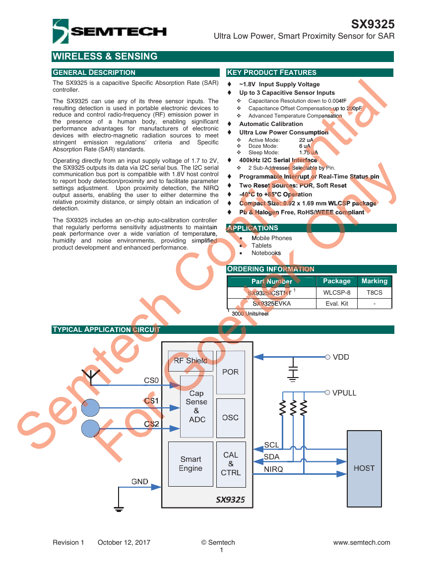
The SX9325 is a capacitive Specific Absorption Rate (SAR)
controller.
The SX9325 can use any of its three sensor inputs. The
resulting detection is used in portable electronic devices to
reduce and control radio-frequency (RF) emission power in
the presence of a human body, enabling significant
performance advantages for manufacturers of electronic
devices with electro-magnetic radiation sources to meet
stringent emission
regulations' criteria and Specific
Absorption Rate (SAR) standards.
Operating directly from an input supply voltage of 1.7 to 2V,
the SX9325 outputs its data via I2C serial bus. The I2C serial
communication bus port is compatible with 1.8V host control
to report body detection/proximity and to facilitate parameter
settings adjustment. Upon proximity detection, the NIRQ
output asserts, enabling the user to either determine the
relative proximity distance, or simply obtain an indication of
detection.
The SX9325 includes an on-chip auto-calibration controller
r
that regularly performs sensitivity adjustments to maintain
tain
peak performance over a wide variation of temperature,
ature,
humidity and noise environments, providing simplified
implified
ied
product development and enhanced performance.
Confidential
Only Status pin
S/WEEE compliant On
b & HalogennfAPPLICATIO
o
GGoGGGGGoertekoks okek ORMATIONtek
tekrt NumbeekSX9325ICSTRT
SX9325rtert1 3000 Units/reel
SX9325ICSTRT 1teSX9325EV
Semtech
echCIRCUIT
00 Units/reeloer
GoeoeooGoGo
mmtmtmt
emem
FoForr rorrrorr
FoFF
Package Marking
WLCSP-8
T8CS
Eval. Kit
Mobile Phones
Mo
Mo
Notebooks
Tablets
Part Number
SX9325ICSTRT 1
SX9325EVKA
TYPICAL APPLICATION CIRCUIT
1 3000 Units/reel
APPLICATIONS
ORDERING INFORMATION
-
Revision 1 October 12, 2017
© Semtech
1
www.semtech.com
�
WIRELESS & SENSING
SX9325
Ultra Low Power, Smart Proximity Sensor for SAR
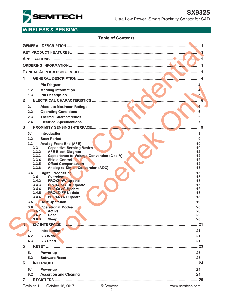
Table of Contents
......
.............................
.........................
..............................
..................
........................
.................
1.1
1.2
1.3
2.1
2.2
2.3
2.4
3.1
3.2
3.3
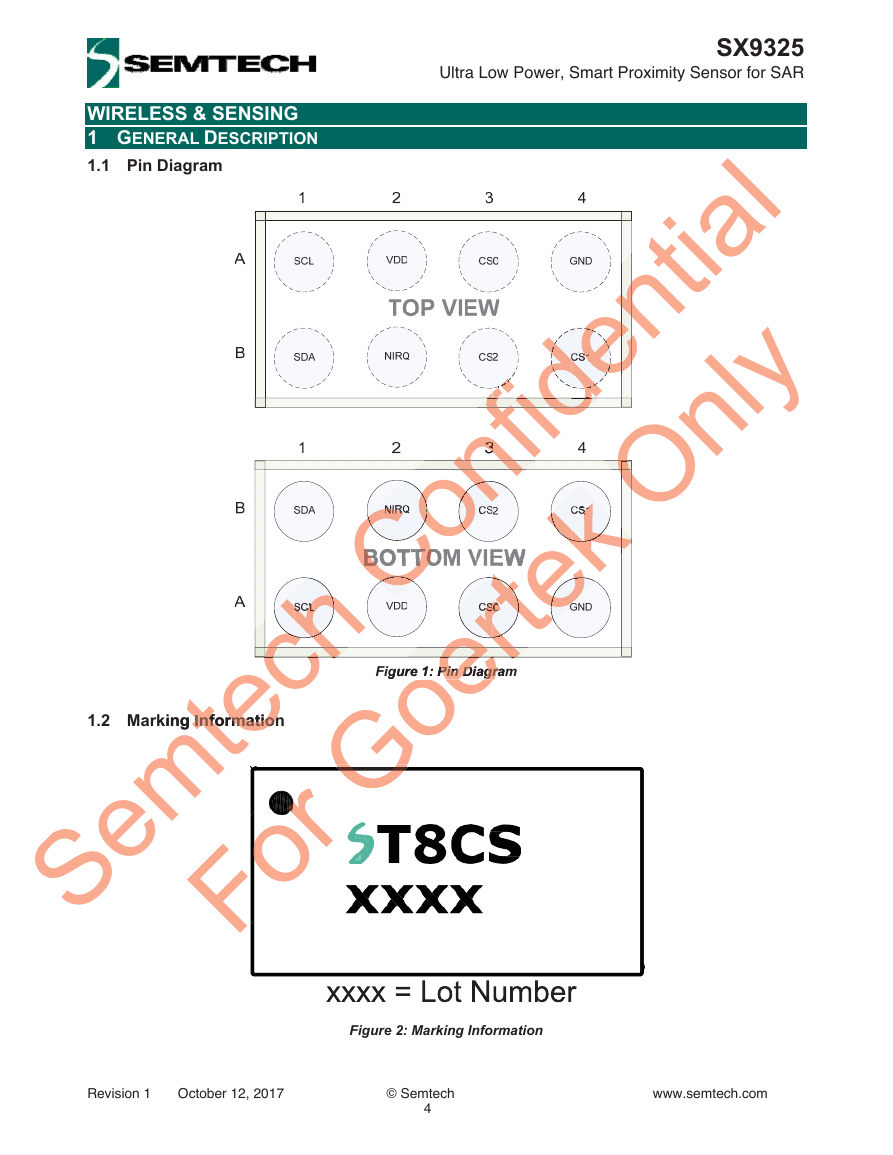
Pin Diagram
Marking Information
Pin Description
Introduction
Scan Period
Analog Front-End (AFE)
Absolute Maximum Ratings
Operating Conditions
Thermal Characteristics
Electrical Specifications
.................
..............................
.........................
.............................
......................
.................
.............................
Confidential ..............
Only44
Goertek ....
Semtech B
For es
GENERAL DESCRIPTION .......................................................................................................................... 1
KEY PRODUCT FEATURES ....................................................................................................................... 1
...................... 1
............... 1
APPLICATIONS ......................................................................................................................................... 1
........................ 1
...........
ORDERING INFORMATION ........................................................................................................................ 1
TYPICAL APPLICATION CIRCUIT .............................................................................................................. 1
GENERAL DESCRIPTION ................................................................................................................. 4
1
4
4
44
5
55
ELECTRICAL CHARACTERISTICS ................................................................................................... 6
....................... 6
........... 6
6
66
6
6
6
6
7
PROXIMITY SENSING INTERFACE ................................................................................................... 9
9
9
10
10
12
12
12
12
13
13
13
15
15
16
18
18
19
20
3.6.1
3.6.13.6.1
20
3.6.2
3.6.23.6.2
20
3.6.3
3.6.36.3
20
I2C INTERFACE ............................................................................................................................. 21
I2CI2C
21
21
21
RESET ........................................................................................................................................... 23
23
23
INTERRUPT .................................................................................................................................... 24
24
24
REGISTERS ................................................................................................................................... 25
www.semtech.com
Digital Processing
rocessing ng
Overview
erview ew
PROXRAW Update
PROXRAW Update
PROXRAW Update
PROXUSEFUL Update
PROXUSEFUL Up
PROXUSEFUL
PROXAVG Update
PROXAVG Upd
ROXAVG Upd
PROXDIFF Update
PROXDIFF U
PROXDIFF
PROXSTA
PROXSTAT Update
PROXSTA
Host Operation
Host Opera
Host Opera
Operational Modes
Operatio
Operati
Capacitive Sensing Basics
am
AFE Block Diagram
Capacitance-to-Voltage Conversion (C-to-V)
o-Voltage Co
-Voltage C
V)
Shield Control
ol
Offset Compensation
mpensation
ation
Analog-to-Digital Conversion (ADC)
)
to-Digital Conversio
Active
A
Doze
Sleep
FACE ...................
.............
FACE
Introduction
duction
duction
I2C Write
te te
I2C Read
7
Revision 1 October 12, 2017
3.3.1
3.3.2
3.3.3
3.3.4
3.3.5
3.3.6
3.4.1
3.4.2
3.4.3
3.4.4
3.4.5
4.5
3.4.6
3.4.6
Power-up
Assertion and Clearing
4.1
4.4
4.2
4.3
5.1
5.2
6.1
6.2
Power-up
Software Reset
3.4
3.5
3.5
3.6
3.6
© Semtech
2
2
3
4
44
5
6
sio
gital Conve
�
WIRELESS & SENSING
8
8.1
8.2
9.1
9.2
9
SX9325
Ultra Low Power, Smart Proximity Sensor for SAR
Outline Drawing
Land Pattern
Typical Application Circuit
External Components Recommended Values
APPLICATION INFORMATION ........................................................................................................ 40
40
40
PACKAGING INFORMATION .......................................................................................................... 41
................... 41
............ 4
41
4141
42
44
Semtech Confidential 40
For Goertek Only
Revision 1 October 12, 2017
© Semtech
3
www.semtech.com
�
SX9325
Ultra Low Power, Smart Proximity Sensor for SAR
WIRELESS & SENSING
1 GENERAL DESCRIPTION
1.1 Pin Diagram
Confidential
fidfiden
fide
Only
ononf
OOO
CCo
ertek
kek
erte
te
Semtech
chcch
er
Goe
Fo
1.2 Marking Information
rking Information
Information
Figure 1: Pin Diagram
Figure 1: Pin Diagram
Pin Diagr
Figure 2: Marking Information
Revision 1 October 12, 2017
© Semtech
4
www.semtech.com
�
Digital Input
SDA
NIRQ
Digital Input/Output
Digital Input/Output
SX9325
Ultra Low Power, Smart Proximity Sensor for SAR
Number
put or I2C Sub-Address
2C Sub-Addre
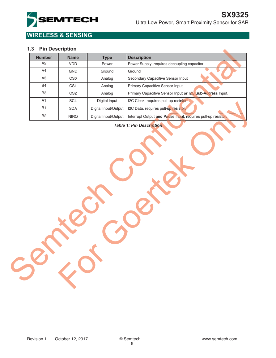
Table 1: Pin Description
ription
A2
A4
A3
B4
B3
A1
B1
B2
Type
Power
Ground
Analog
Analog
Analog
I2C Data, requires pull-up resistor.
Interrupt Output and Pause Input, requires pull-up resistor.
Pause Input, requ
WIRELESS & SENSING
1.3 Pin Description
Name
VDD
GND
CS0
CS1
CS2
SCL
Description
Power Supply, requires decoupling capacitor.
Ground
Secondary Capacitive Sensor Input
Primary Capacitive Sensor Input
Primary Capacitive Sensor Input or I2C Sub-Address Input.
p resistor.
I2C Clock, requires pull-up resistor.
ause Input, requdential alllalalial
tiati
rnt
stor. enull-up resistor.
up resistor. den
de
Semtech Confideanda
stor. lyynlyyy
For Goertek Onlyyyp resistor.
fidscription
Revision 1 October 12, 2017
© Semtech
5
www.semtech.com
�
SX9325
Ultra Low Power, Smart Proximity Sensor for SAR
Symbol
Table 3: Operating Conditions
Max
2.2
3.9
VDD+0.3
Min
-0.5
-0.5
-0.5
-0.5
-10
-40
-
-50
8
e device. Th
s beyond the “Opera
beyond the “Opera
d periods may affect
VDD
VPULL
VIN
IIN
TJCT
TRE
TSTOR
ESDHBM
Parameter
Supply Voltage
Pull-up Voltage
Input Voltage (non-supply pins)
Input Current (non-supply pins)
Operating Junction Temperature
Reflow Temperature
Storage Temperature
ESD HBM (ANSI/ESDA/JEDEC JS-001)
WIRELESS & SENSING
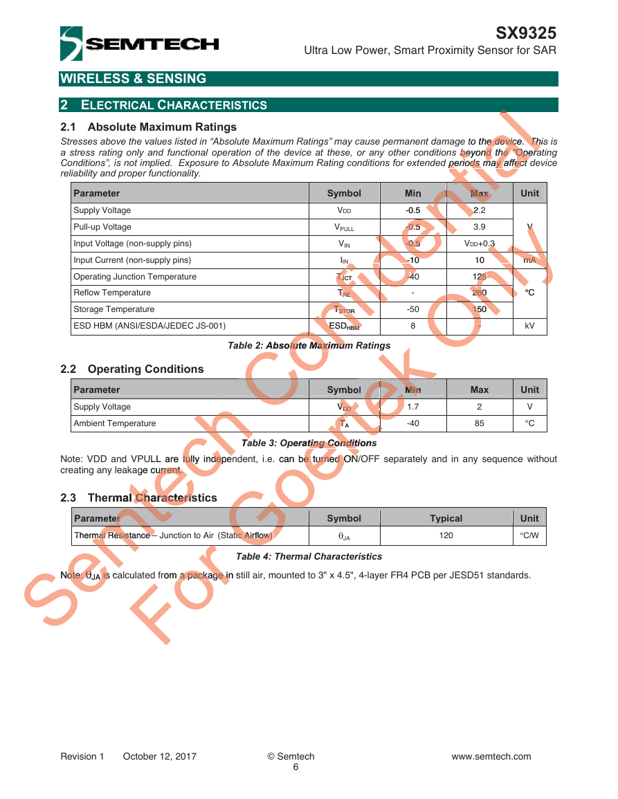
2 ELECTRICAL CHARACTERISTICS
2.1 Absolute Maximum Ratings
Stresses above the values listed in “Absolute Maximum Ratings” may cause permanent damage to the device. This is
a stress rating only and functional operation of the device at these, or any other conditions beyond the “Operating
Conditions”, is not implied. Exposure to Absolute Maximum Rating conditions for extended periods may affect device
reliability and proper functionality.
CCCConfidentiall to the device. This
periods may affect ntntntintiMax ttia
nt-0.5
2.22ntntnt
ent
den-0.5
-0.5 enenen
-0.5 dddeeede-10
-10 ddde
OnlyV V y3 3yylyy10
260Onlynlyy
mA mA lylylyynlyy125 25
°C nlynlynlyynlyy
Ony
fidTTJCTJ
-40-4fidfidfidfidTTRERE fidfidfidfid
150 15OOOnnOn- - OOOOOO
TTSTORSTO nfifififESDE
HBMBM nf
ooon: Absolute Maximum
Goertek gs
tek
tetek
tekMinekek
tekVVDDDD
lute MaximumCC
teteteteTTA Arteteterttetperating Conditions
Semtech hhhh Ta
mteermtemtemtThermal Resistance –
GoGoGoGtic Airflow)
mal Resistance –mtmNote:
tic Airflow) GGle
For o Arfrom a package in s
Note: JA is calculated from a package in still air, mounted to 3" x 4.5", 4-layer FR4 PCB per JESD51 standards.
ote: JAA is c
Note: VDD and VPULL are fully independent, i.e. can be turned ON/OFF separately and in any sequence without
creating any leakage current.
age current.
urrent.
ULL are fully indepen
fully indepe
Parameter
Thermal Resistance – Junction to Air (Static Airflow)
VDD
TA
ting Condit
e. can be turned ON
e turned ON
Parameter
Supply Voltage
Ambient Temperature
2.3 Thermal Characteristics
rmal Characteris
Characteris
2.2 Operating Conditions
Table 2: Absolute Maximum Ratings
Unit
V
mA
°C
kV
Unit
V
°C
10
125
260
260
150
-
Max
2
85
Table 4: Thermal Characteristics
Symbol
JA
Typical
120
Unit
°C/W
Symbol
Min
1.7
1
-40
isAA
a package in
Revision 1 October 12, 2017
© Semtech
6
www.semtech.com
�
SX9325
Ultra Low Power, Smart Proximity Sensor for SAR
Min
1.75
1.75
IACTIVE
Doze
Active
ISLEEP
IDOZE
+/-1.325
CRANGEL
CRANGEH
6
6
22
Typ.
Max
Unit
-
-
-
-
5
14
1
45
Measurement Range
AGAIN=1000,
GAIN01/23=001
Symbol Conditions
Power down. (I2C listening)
PHEN = 0000
Capacitive Sensing Interface
SCANPERIOD = 30ms
FREQ = 100kHz
RESOLUTION = 64
PHEN = 0001
SCANPERIOD = 400ms
FREQ = 100kHz
RESOLUTION = 64
PHEN = 0001
E01/23 =
ARANGE01/23 =
mall
0/Small
ARANGE01/23 =
NGE01/23 =
1/Large
1/Large
Parameter
Current Consumption
Sleep
(no phase enabled)
WIRELESS & SENSING
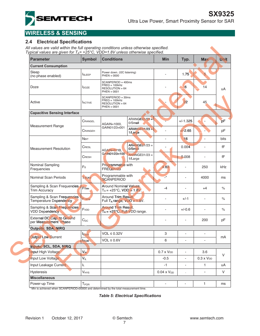
2.4 Electrical Specifications
All values are valid within the full operating conditions unless otherwise specified.
Typical values are given for TA= +25°C, VDD=1.8V unless otherwise specified.
Confidentialalalax alal Unitalal
tialal
tial
ntia
5 5 tititiaaa
6 ntintinti
ent
den
22 22eeennn
fidediddeideee
Only5 ylyynlynlylylylylyynlyy325
Onlyy
pnlynlynlyy
fidNGE01/23 =
- fidfidfidfidARANGE01/23 =
- OOOnnnOOn16
LargenfifififinGAIN=0110,
16 OOOOOO04
4OOOO
0/Small malooon
CoARANARAN
1/LCoCoCCo
Goertek- kk-
0.kkkek4.63
4.63 eeekkk
tek
Q01/23CC
*teteterte
Semtech TTSCANSCAN
D = 1.8V.ertrtrtrt
SCASChchencies s FFTrim
ArccchhhchFrequencies
Tempecececec& Scan Frequencies
+25°C, Full VDGoe
nge, VDD = 1.8VeAround Trim Result.
asurement Phamte
pendency cyteeeernal DC Cap. to Groun
GGGGoGGGLG
eemuts: SDA, NmeOutput Low Cu
Output Low CeemeSeSeSeSeInputs: SSeSeInput
InSeSeSe
ForrIOL04OL04 rIIOL06OL06 ooror
ForNIRorge ge
VIHIH Fooooge ge
VFoooo
InInSSS
ent ent FF
rogrammable
rogrammable
Programmable with
EQ01/23
FREQ01/23
Programmable with
P
h
SCANPERIOD
Around Nominal Values.
inal Values.
Values.
TA = +25°C, VDD = 1.8V.
C, VDD = 1.8V.
Around Trim Result.
d Trim Result.
m Result.
Full TA range, VDD = 1.8V.
TA range, VDD = 1.8V
Around Trim Result
Around Trim Result.
TA = +25°C, Full VDD range.
TTA = +25°C, Full VD
Sampling & Scan Frequencies
Trim Accuracy
uencies
Sampling & Scan Frequencies
Temperature Dependency
ependency
enc
Sampling & Scan Frequencies
an Frequencies
VDD Dependency
External DC Cap. to Ground
C Cap. to Groun
per Measurement Phase
er Measurement Phase
Outputs: SDA, NIRQ
ARANGE01/
ANGE01
ARANGE01/23 =
0/Small
ARANGE01/23 =
1/Large
Nominal Sampling
Frequencies
VOL 0.32V
VOL 0.6V
VIH
VIL
IL
VHYS
Measurement Resolution
AGAIN=0110,
GAIN=01
GAIN01/23=100
GAIN01/23=100
GAIN01/23=100
Nominal Scan Periods
Output Low Current
-
-
-
-
-
-
-
IOL04
IOL06
-
-
-
-
-
-
-
-
-
-
%
%
%
-
-
-
-
-
-
0.04 x VDD
-0.5
-1
V
uA
V
pF
pF
pF
bits
-
-
-
-
NBIT
CRESL
-
-
-
3
6
0.7 x VDD
FTrim
FFTemp
FTemp
FVDD
kHz
ms
0.004
0.008
0.0
0.3 x VDD
250
4000
200
pF
+/-1
+/-0.6
+/-2.65
+/-2.65
+/-2.65
16
CRESH
FS
TSCAN
3.6
1
-
4.63
-*
-4
-
-
-
uA
fF
fF
CDC
mA
+4
Inputs: SCL, SDA, NIRQ
Input High Voltage
Input Low Voltage
Input Leakage Current
Hysteresis
Miscellaneous
Power-up Time
TPOR
-
-
1
ms
* Min is achieved when SCANPERIOD=00000 and determined by the total measurement time.
Table 5: Electrical Specifications
Revision 1 October 12, 2017
© Semtech
7
www.semtech.com
�
WIRELESS & SENSING
Parameter
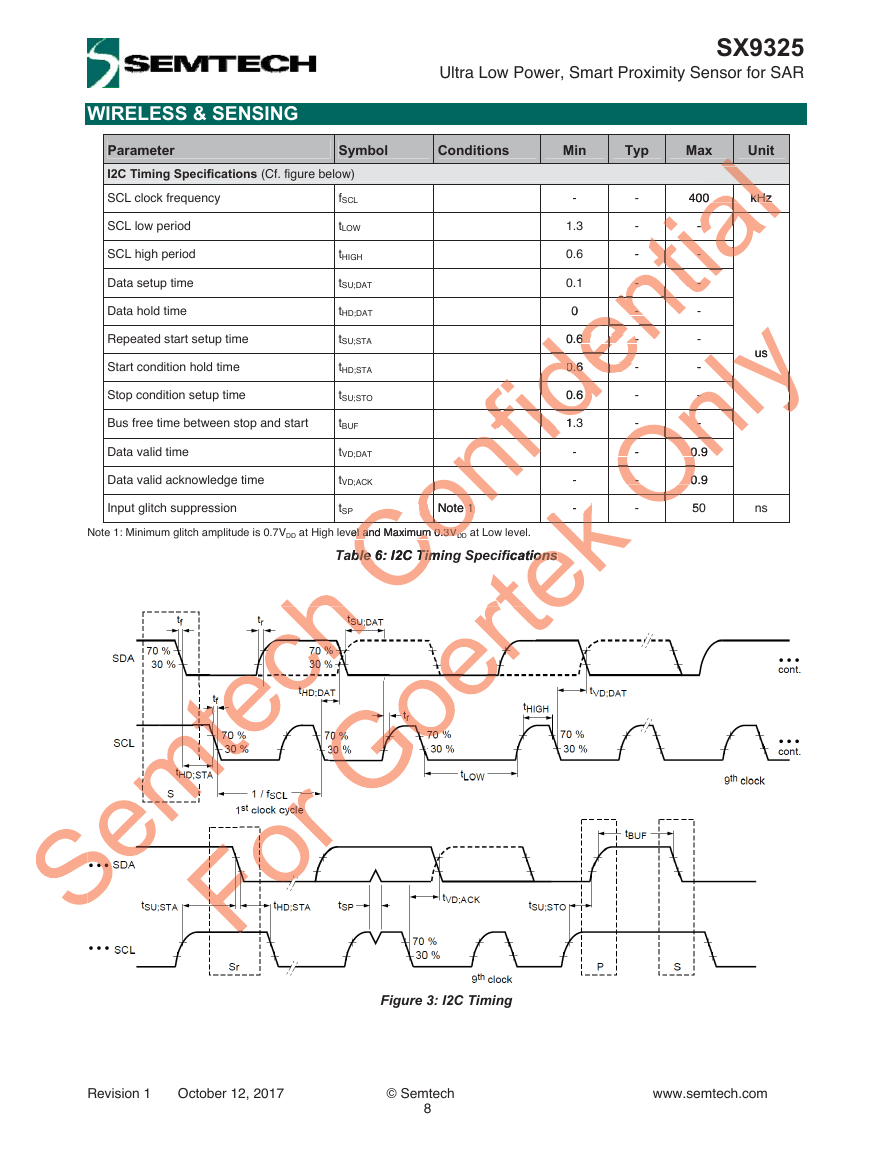
I2C Timing Specifications (Cf. figure below)
SCL clock frequency
fSCL
SCL low period
SCL high period
Data setup time
Data hold time
Repeated start setup time
Start condition hold time
Stop condition setup time
Bus free time between stop and start
Data valid time
Data valid acknowledge time
Input glitch suppression
Note 1: Minimum glitch amplitude is 0.7VDD at High level and Maximum 0.3VDD at Low level.
tSP
SX9325
Ultra Low Power, Smart Proximity Sensor for SAR
-
-
-
0.1
0
0
1.3
0.6
400
-
-
-
-
-
-
-
-
-
kHz
kHz
-
-
-
-
tLOW
tHIGH
Max
Min
Typ
Unit
tSU;STA
tHD;STA
tSU;DAT
tHD;DAT
Symbol
Conditions
Confidential llllll400
kHz lallal- - ialalal
ntia
tia-
- - tititiaa
- ntintintinti
- - ntntnt
en0.6
- eeennn
de0.6 0.6 dddeeeide0.6 idfidideee
Onlyus yyy- ylyylyy- - lynlyynlyy
- OOOnlynlyy
Ony
fid1.fidfidfidfid
0OOOnnOOn
nfififif onoNote 1 1 oCoon
0OOOOOO 50OOOO
CoCoCovel and Maximum 0.3V
rtek - - kkkk.
el and Maximum 0.3VDD
Table 6: I2C Timing Specifications
able 6: I2C Timin
ifications
ions
ble 6: I2C Tim
Note 1
tVD;ACK
tSU;STO
tVD;DAT
-
-
-
-
-
-
-
-
-
-
-
tBUF
-
-
-
-
-
-
-
0.9
0.9
0.6
6
0.6
0.6
1.3
0.9
0.9
50
ns
us
Figure 3: I2C Timing
Revision 1 October 12, 2017
© Semtech
8
www.semtech.com
�



 2023年江西萍乡中考道德与法治真题及答案.doc
 2012年重庆南川中考生物真题及答案.doc
 2013年江西师范大学地理学综合及文艺理论基础考研真题.doc
 2020年四川甘孜小升初语文真题及答案I卷.doc
 2020年注册岩土工程师专业基础考试真题及答案.doc
 2023-2024学年福建省厦门市九年级上学期数学月考试题及答案.doc
 2021-2022学年辽宁省沈阳市大东区九年级上学期语文期末试题及答案.doc
 2022-2023学年北京东城区初三第一学期物理期末试卷及答案.doc
 2018上半年江西教师资格初中地理学科知识与教学能力真题及答案.doc
 2012年河北国家公务员申论考试真题及答案-省级.doc
 2020-2021学年江苏省扬州市江都区邵樊片九年级上学期数学第一次质量检测试题及答案.doc
 2022下半年黑龙江教师资格证中学综合素质真题及答案.doc