BROADCASTING DIVISION
Application Note
The digital Video Standard
according to
ITU-R BT. 601/656
Products:
CCVS+COMPONENT GENERATOR
CCVS GENERATOR
DIGITAL VIDEO COMPONENT ANALYSER
SAF
SFF
VCA
7BM19_0E
�
ITU-R BT. 601
Leveldiagram at the input of an A/D converter for the
analogue component signals Y , CB , CR
1
EY
0
255/1023 (FF.C h)
235/940 (EB.0 h)
Y
16/64 (10.0 h)
0/0 (00.0 h)
+0.5
ECB
ECR
0
-0.5
255/1023 (FF.C h)
240/960 (F0.0 h)
128/512 (80.0h)
16/64 (10.0 h)
0/0 (00.0 h)
CB
CR
BROADCASTING DIVISION
2
�
ITU-R BT. 601
Example for digital synchronizing signals
in the parallel interface (10 bit )
EAV
SAV
D0
D1
D2
D3
D4
D5
D6
D7
D8
D9
black points indicate the value 1 , white points 0
XY within EAV is DA.0 ( 11011010 00)
XY within SAV is C7.0 ( 1100011100 ) this significates
this line an active one in an even field
BROADCASTING DIVISION
3
�
ITU-R BT. 601
Data format and timing relationship with the
analogue video signal
horizontal
blanking
analogue
0H
16 T (625)
8 T (525)
24 T (625)
32 T (525)
24 T (625)
32 T (525)
E
A
V
4 T
Audio, EDH, Data (ANC)
S
A
V
Videodata-Multiplex
CB Y CR Y CB Y CR Y ............
E
A
V
4 T
blanking interval
digital 288 T (625)
276 T (525) digital line
1728 T (625)
1716 T (525)
Video Data
1440 T
BROADCASTING DIVISION
0H
4
�
ITU-R BT. 601
structure of digital synchronizing signals
code word
first word
second word
third word
fourth word
( FF.C)
( 00.0)
( 00.0)
( XY.0)
bit number
9 8 7 6 5 4 3 2 1 0
1 1 1 1 1 1 1 1 1 1
0 0 0 0 0 0 0 0 0 0
0 0 0 0 0 0 0 0 0 0
1 F V H P3 P2 P1 P0 0 0
F = 0 first field
F = 1 second field
V = 0 or 1 ( in VBI )
H = 0 in SAV
H = 1 in EAV
P0, P1, P2, P3 see table of control bits
BROADCASTING DIVISION
5
�
ITU-R BT. 601
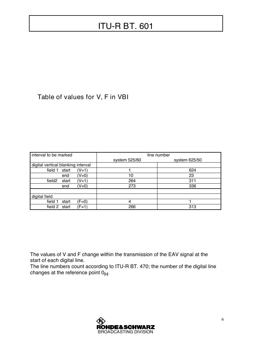
Table of values for V, F in VBI
interval to be marked
digital vertical blanking interval
field 1 start
end
field2 start
end
(V=1)
(V=0)
(V=1)
(V=0)
digital field
field 1 start
field 2 start
(F=0)
(F=1)
system 525/60
line number
system 625/50
1
10
264
273
4
266
624
23
311
336
1
313
The values of V and F change within the transmission of the EAV signal at the
start of each digital line.
The line numbers count according to ITU-R BT. 470; the number of the digital line
changes at the reference point 0H.
BROADCASTING DIVISION
6
�
ITU-R BT. 601
Table of controlbits
const.
1
1
1
1
1
1
1
1
F
0
0
0
0
1
1
1
1
V H P3 P2 P1 P0 const.
0
0
1
1
0
0
1
1
0
0
0
0
0
0
0
0
0
1
0
1
1
0
1
0
0
0
1
1
1
1
0
0
0
1
1
0
1
0
0
1
0
1
0
1
0
1
0
1
0
1
1
0
0
1
1
0
const.
0
0
0
0
0
0
0
0
XY.0
80.0
9D.0
AB.0
B6.0
C7.0
DA.0
EC.0
F1. 0
level dec.
128.0
151.0
171.0
182.0
199.0
218.0
236.0
241.0
1st field
2nd field
active
picture
VBI
active
picture
VBI
SAV
EAV
SAV
EAV
SAV
EAV
SAV
EAV
BROADCASTING DIVISION
7
�
Signal Timing and Levels
(parallel interface)
timing reference for data and clock
ECL level
-0.8 V
-1.6 V
data
-0.8 V
-1.6 V
clock
<
t d
>
<
<
t
>
T
>
Clock-to-data Timing (at source)
clock period (625):
clock period (525):
clock pulse width:
data timing - sending end:
f H = line frequency
T = 1/ (1728 x f H) = 37.037 ns
T = 1/ (1716 x f H) = 37.037 ns
t = 18.52 – 3 ns
t d = 18.5 – 3 ns
variation of data timing - sending end in SAF and SFF :
18.5 – 10 ns
BROADCASTING DIVISION
8
�


 2023年江西萍乡中考道德与法治真题及答案.doc
 2012年重庆南川中考生物真题及答案.doc
 2013年江西师范大学地理学综合及文艺理论基础考研真题.doc
 2020年四川甘孜小升初语文真题及答案I卷.doc
 2020年注册岩土工程师专业基础考试真题及答案.doc
 2023-2024学年福建省厦门市九年级上学期数学月考试题及答案.doc
 2021-2022学年辽宁省沈阳市大东区九年级上学期语文期末试题及答案.doc
 2022-2023学年北京东城区初三第一学期物理期末试卷及答案.doc
 2018上半年江西教师资格初中地理学科知识与教学能力真题及答案.doc
 2012年河北国家公务员申论考试真题及答案-省级.doc
 2020-2021学年江苏省扬州市江都区邵樊片九年级上学期数学第一次质量检测试题及答案.doc
 2022下半年黑龙江教师资格证中学综合素质真题及答案.doc