Globalsat Technology Corporation
PRODUCT USER MANUAL
GPS ENGINE BOARD
ET-212 version 1.2
GlobalSat Technology Corporation
16, No.186,Chien 1 Road, 235Chung Ho City,Taipei Hsien, Taiwan ,R.O.C.
Tel: 886-2-8226-3799(Rep.) Fax: 886-2-8226-3899
Web: www.globalsat.com.tw E-mail: service@globalsat.com.tw
�
SiRF GSC2x
L1, 1575.42 MHz
1.023 MHz chip rate
12 channel all-in-view tracking
-155 dBm
Features:
SiRF GSC2x high performance GPS Chip Set
Very high sensitivity (Tracking Sensitivity: -155 dBm)
Extremely fast TTFF (Time To First Fix) at low signal level
Compact size (27.9mm * 20 mm * 3.4mm) suitable for space-sensitive application
One size component, easy to mount on another PCB board
Support NMEA 0183 and SiRF binary protocol
Specification:
General
Chipset
Frequency
C/A code
Channels
Sensitivity
Accuracy
Position
Velocity
Time
Datum
Default
Acquisition Time
Reacquisition
Hot start
Warm start
Cold start
Dynamic Conditions
Altitude
Velocity
Acceleration
Jerk
18,000 meters (60,000 feet) max
515 meters /second (1000 knots) max
Less than 4g
20m/sec **3
10 meters, 2D RMS
5 meters, 2D RMS, WAAS enabled
0.1 m/s
1us synchronized to GPS time
0.1 sec., average
8 sec., average
38 sec., average
45 sec., average
WGS-84
�
Power
Main power input
Power consumption
Interface
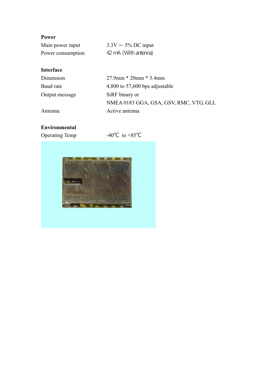
Dimension
Baud rate
Output message
Antenna
Environmental
Operating Temp
3.3V +- 5% DC input
42 mA (With antenna)
27.9mm * 20mm * 3.4mm
4,800 to 57,600 bps adjustable
SiRF binary or
NMEA 0183 GGA, GSA, GSV, RMC, VTG, GLL
Active antenna
-40℃ to +85℃
�
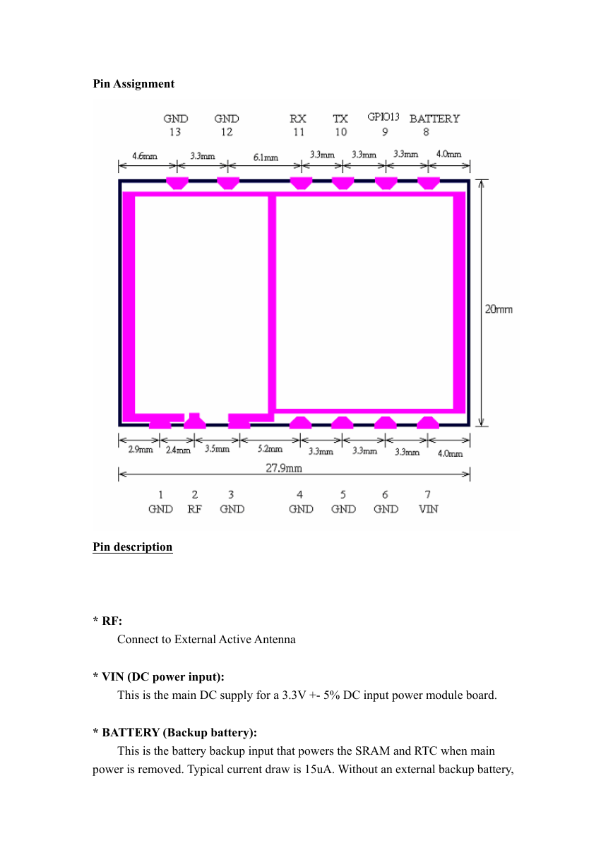
Pin Assignment
Pin description
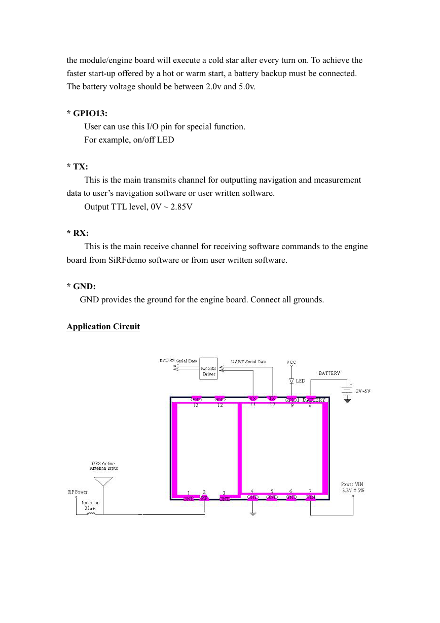
* RF:
* VIN (DC power input):
* BATTERY (Backup battery):
power is removed. Typical current draw is 15uA. Without an external backup battery,
This is the main DC supply for a 3.3V +- 5% DC input power module board.
Connect to External Active Antenna
This is the battery backup input that powers the SRAM and RTC when main
�
User can use this I/O pin for special function.
For example, on/off LED
the module/engine board will execute a cold star after every turn on. To achieve the
faster start-up offered by a hot or warm start, a battery backup must be connected.
The battery voltage should be between 2.0v and 5.0v.
* GPIO13:
* TX:
data to user’s navigation software or user written software.
* RX:
board from SiRFdemo software or from user written software.
* GND:
This is the main receive channel for receiving software commands to the engine
This is the main transmits channel for outputting navigation and measurement
Output TTL level, 0V ~ 2.85V
GND provides the ground for the engine board. Connect all grounds.
Application Circuit
�
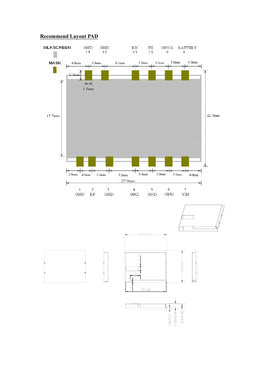
Recommend Layout PAD
�
SOFTWARE COMMAND
NMEA Output Command
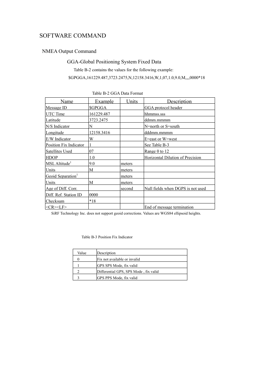
GGA-Global Positioning System Fixed Data
Table B-2 contains the values for the following example:
$GPGGA,161229.487,3723.2475,N,12158.3416,W,1,07,1.0,9.0,M,,,,0000*18
Table B-2 GGA Data Format
Name
Example
$GPGGA
Message ID
161229.487
UTC Time
3723.2475
Latitude
N
N/S Indicator
12158.3416
Longitude
E/W Indicator
W
Position Fix Indicator 1
07
Satellites Used
1.0
HDOP
MSL Altitude1
9.0
M
Units
Geoid Separation1
M
Units
Age of Diff. Corr.
0000
Diff. Ref. Station ID
*18
Checksum
Units
Description
GGA protocol header
hhmmss.sss
ddmm.mmmm
N=north or S=south
dddmm.mmmm
E=east or W=west
See Table B-3
Range 0 to 12
Horizontal Dilution of Precision
meters
meters
meters
meters
second
Null fields when DGPS is not used
End of message termination
SiRF Technology Inc. does not support geoid corrections. Values are WGS84 ellipsoid heights.
Table B-3 Position Fix Indicator
Value
0
1
2
3
Description
Fix not available or invalid
GPS SPS Mode, fix valid
Differential GPS, SPS Mode , fix valid
GPS PPS Mode, fix valid
�
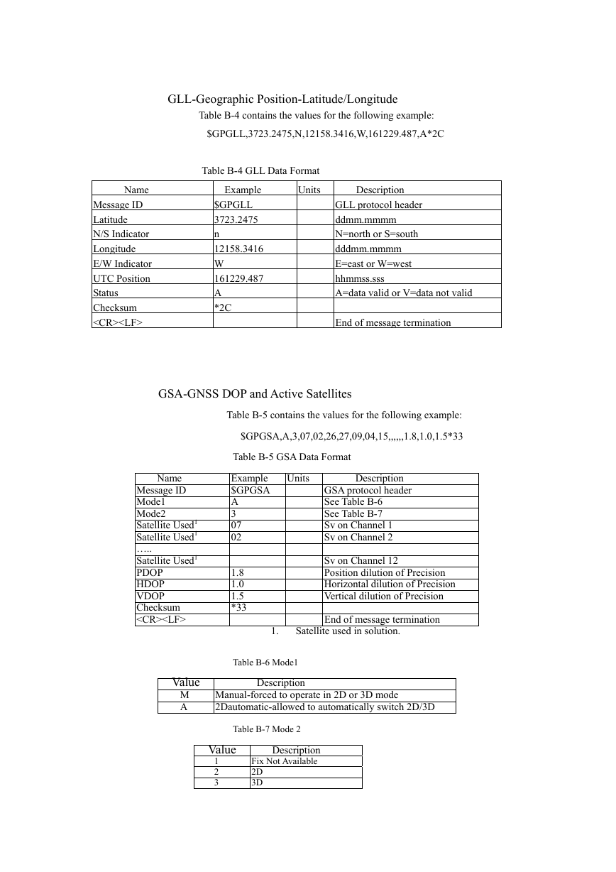
GLL-Geographic Position-Latitude/Longitude
Table B-4 contains the values for the following example:
$GPGLL,3723.2475,N,12158.3416,W,161229.487,A*2C
Table B-4 GLL Data Format
Name
Units
Message ID
Latitude
N/S Indicator
Longitude
E/W Indicator
UTC Position
Status
Checksum
Description
GLL protocol header
ddmm.mmmm
N=north or S=south
dddmm.mmmm
E=east or W=west
hhmmss.sss
A=data valid or V=data not valid
Example
$GPGLL
3723.2475
n
12158.3416
W
161229.487
A
*2C
End of message termination
GSA-GNSS DOP and Active Satellites
Table B-5 contains the values for the following example:
$GPGSA,A,3,07,02,26,27,09,04,15,,,,,,1.8,1.0,1.5*33
Table B-5 GSA Data Format
Name
Message ID
Mode1
Mode2
Satellite Used1
Satellite Used1
…..
Satellite Used1
PDOP
HDOP
VDOP
Checksum
Example
$GPGSA
A
3
07
02
1.8
1.0
1.5
*33
Units
Description
GSA protocol header
See Table B-6
See Table B-7
Sv on Channel 1
Sv on Channel 2
Sv on Channel 12
Position dilution of Precision
Horizontal dilution of Precision
Vertical dilution of Precision
End of message termination
Satellite used in solution.
1.
Table B-6 Mode1
Description
Value
M
A
Manual-forced to operate in 2D or 3D mode
2Dautomatic-allowed to automatically switch 2D/3D
Table B-7 Mode 2
Value
1
2
3
Description
Fix Not Available
2D
3D
�


 2023年江西萍乡中考道德与法治真题及答案.doc
 2012年重庆南川中考生物真题及答案.doc
 2013年江西师范大学地理学综合及文艺理论基础考研真题.doc
 2020年四川甘孜小升初语文真题及答案I卷.doc
 2020年注册岩土工程师专业基础考试真题及答案.doc
 2023-2024学年福建省厦门市九年级上学期数学月考试题及答案.doc
 2021-2022学年辽宁省沈阳市大东区九年级上学期语文期末试题及答案.doc
 2022-2023学年北京东城区初三第一学期物理期末试卷及答案.doc
 2018上半年江西教师资格初中地理学科知识与教学能力真题及答案.doc
 2012年河北国家公务员申论考试真题及答案-省级.doc
 2020-2021学年江苏省扬州市江都区邵樊片九年级上学期数学第一次质量检测试题及答案.doc
 2022下半年黑龙江教师资格证中学综合素质真题及答案.doc