logo资料库

mspg2553中文资料.pdf

第1页 / 共658页
第2页 / 共658页
第3页 / 共658页
第4页 / 共658页
第5页 / 共658页
第6页 / 共658页
第7页 / 共658页
第8页 / 共658页
资料共658页,剩余部分请下载后查看
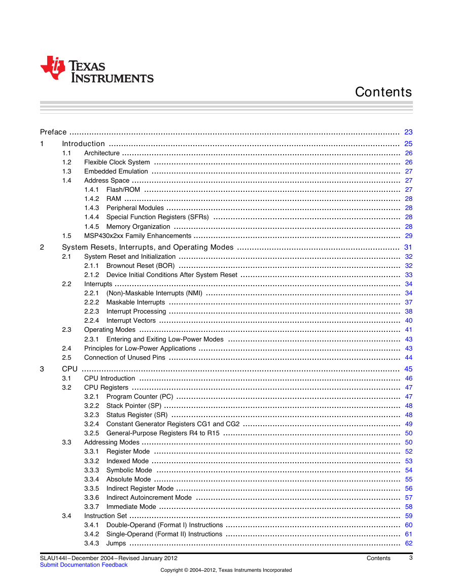
Table of Contents
Preface
1 Introduction
1.1 Architecture
1.2 Flexible Clock System
1.3 Embedded Emulation
1.4 Address Space
1.4.1 Flash/ROM
1.4.2 RAM
1.4.3 Peripheral Modules
1.4.4 Special Function Registers (SFRs)
1.4.5 Memory Organization
1.5 MSP430x2xx Family Enhancements
2 System Resets, Interrupts, and Operating Modes
2.1 System Reset and Initialization
2.1.1 Brownout Reset (BOR)
2.1.2 Device Initial Conditions After System Reset
2.1.2.1 Software Initialization
2.2 Interrupts
2.2.1 (Non)-Maskable Interrupts (NMI)
2.2.1.1 Reset/NMI Pin
2.2.1.2 Flash Access Violation
2.2.1.3 Oscillator Fault
2.2.1.4 Example of an NMI Interrupt Handler
2.2.2 Maskable Interrupts
2.2.3 Interrupt Processing
2.2.3.1 Interrupt Acceptance
2.2.3.2 Return From Interrupt
2.2.3.3 Interrupt Nesting
2.2.4 Interrupt Vectors
2.3 Operating Modes
2.3.1 Entering and Exiting Low-Power Modes
2.4 Principles for Low-Power Applications
2.5 Connection of Unused Pins
3 CPU
3.1 CPU Introduction
3.2 CPU Registers
3.2.1 Program Counter (PC)
3.2.2 Stack Pointer (SP)
3.2.3 Status Register (SR)
3.2.4 Constant Generator Registers CG1 and CG2
3.2.4.1 Constant Generator - Expanded Instruction Set
3.2.5 General-Purpose Registers R4 to R15
3.3 Addressing Modes
3.3.1 Register Mode
3.3.2 Indexed Mode
3.3.3 Symbolic Mode
3.3.4 Absolute Mode
3.3.5 Indirect Register Mode
3.3.6 Indirect Autoincrement Mode
3.3.7 Immediate Mode
3.4 Instruction Set
3.4.1 Double-Operand (Format I) Instructions
3.4.2 Single-Operand (Format II) Instructions
3.4.3 Jumps
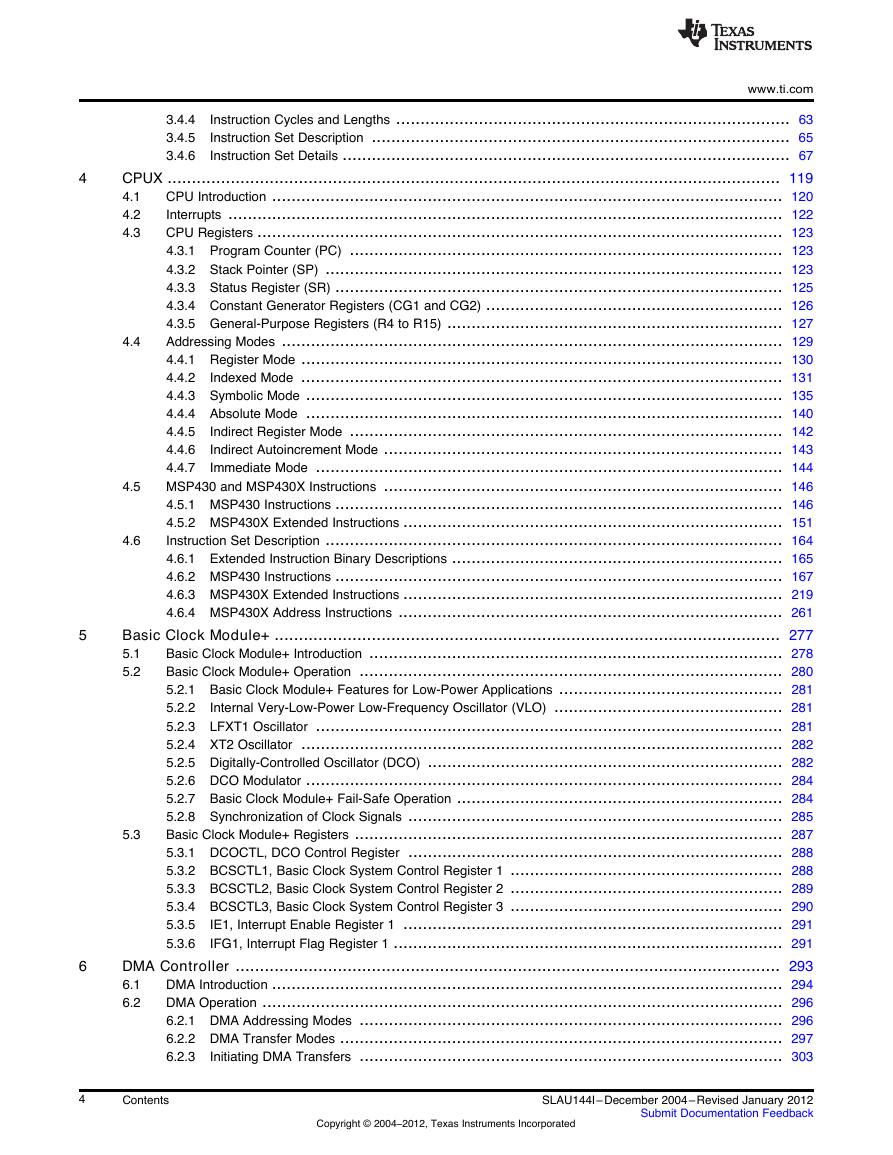
3.4.4 Instruction Cycles and Lengths
3.4.4.1 Interrupt and Reset Cycles
3.4.4.2 Format-II (Single Operand) Instruction Cycles and Lengths
3.4.4.3 Format-III (Jump) Instruction Cycles and Lengths
3.4.4.4 Format-I (Double Operand) Instruction Cycles and Lengths
3.4.5 Instruction Set Description
3.4.6 Instruction Set Details
3.4.6.1 ADC
3.4.6.2 ADD
3.4.6.3 ADDC
3.4.6.4 AND
3.4.6.5 BIC
3.4.6.6 BIS
3.4.6.7 BIT
3.4.6.8 BR, BRANCH
3.4.6.9 CALL
3.4.6.10 CLR
3.4.6.11 CLRC
3.4.6.12 CLRN
3.4.6.13 CLRZ
3.4.6.14 CMP
3.4.6.15 DADC
3.4.6.16 DADD
3.4.6.17 DEC
3.4.6.18 DECD
3.4.6.19 DINT
3.4.6.20 EINT
3.4.6.21 INC
3.4.6.22 INCD
3.4.6.23 INV
3.4.6.24 JC, JHS
3.4.6.25 JEQ, JZ
3.4.6.26 JGE
3.4.6.27 JL
3.4.6.28 JMP
3.4.6.29 JN
3.4.6.30 JNC, JLO
3.4.6.31 JNE, JNZ
3.4.6.32 MOV
3.4.6.33 NOP
3.4.6.34 POP
3.4.6.35 PUSH
3.4.6.36 RET
3.4.6.37 RETI
3.4.6.38 RLA
3.4.6.39 RLC
3.4.6.40 RRA
3.4.6.41 RRC
3.4.6.42 SBC
3.4.6.43 SETC
3.4.6.44 SETN
3.4.6.45 SETZ
3.4.6.46 SUB
3.4.6.47 SUBC, SBB
3.4.6.48 SWPB
3.4.6.49 SXT
3.4.6.50 TST
3.4.6.51 XOR
4 CPUX
4.1 CPU Introduction
4.2 Interrupts
4.3 CPU Registers
4.3.1 Program Counter (PC)
4.3.2 Stack Pointer (SP)
4.3.3 Status Register (SR)
4.3.4 Constant Generator Registers (CG1 and CG2)
4.3.4.1 Constant Generator – Expanded Instruction Set
4.3.5 General-Purpose Registers (R4 to R15)
4.4 Addressing Modes
4.4.1 Register Mode
4.4.2 Indexed Mode
4.4.2.1 Indexed Mode in Lower 64-KB Memory
4.4.2.2 MSP430 Instruction With Indexed Mode in Upper Memory
4.4.2.3 MSP430X Instruction With Indexed Mode
4.4.3 Symbolic Mode
4.4.3.1 Symbolic Mode in Lower 64KB
4.4.3.2 MSP430 Instruction With Symbolic Mode in Upper Memory
4.4.3.3 MSP430X Instruction With Symbolic Mode
4.4.4 Absolute Mode
4.4.4.1 Absolute Mode in Lower 64KB
4.4.4.2 MSP430X Instruction With Absolute Mode
4.4.5 Indirect Register Mode
4.4.6 Indirect Autoincrement Mode
4.4.7 Immediate Mode
4.4.7.1 MSP430 Instructions With Immediate Mode
4.4.7.2 MSP430X Instructions With Immediate Mode
4.5 MSP430 and MSP430X Instructions
4.5.1 MSP430 Instructions
4.5.1.1 MSP430 Double-Operand (Format I) Instructions
4.5.1.2 MSP430 Single-Operand (Format II) Instructions
4.5.1.3 Jump Instructions
4.5.1.4 Emulated Instructions
4.5.1.5 MSP430 Instruction Execution
4.5.1.5.1 Instruction Cycles and Length for Interrupt, Reset, and Subroutines
4.5.1.5.2 Format II (Single-Operand) Instruction Cycles and Lengths
4.5.1.5.3 Jump Instructions Cycles and Lengths
4.5.1.5.4 Format I (Double-Operand) Instruction Cycles and Lengths
4.5.2 MSP430X Extended Instructions
4.5.2.1 Register Mode Extension Word
4.5.2.2 Non-Register Mode Extension Word
4.5.2.3 Extended Double-Operand (Format I) Instructions
4.5.2.4 Extended Single-Operand (Format II) Instructions
4.5.2.4.1 Extended Format II Instruction Format Exceptions
4.5.2.5 Extended Emulated Instructions
4.5.2.6 MSP430X Address Instructions
4.5.2.7 MSP430X Instruction Execution
4.5.2.7.1 MSP430X Format II (Single-Operand) Instruction Cycles and Lengths
4.5.2.7.2 MSP430X Format I (Double-Operand) Instruction Cycles and Lengths
4.5.2.7.3 MSP430X Address Instruction Cycles and Lengths
4.6 Instruction Set Description
4.6.1 Extended Instruction Binary Descriptions
4.6.2 MSP430 Instructions
4.6.2.1 ADC
4.6.2.2 ADD
4.6.2.3 ADDC
4.6.2.4 AND
4.6.2.5 BIC
4.6.2.6 BIS
4.6.2.7 BIT
4.6.2.8 BR, BRANCH
4.6.2.9 CALL
4.6.2.10 CLR
4.6.2.11 CLRC
4.6.2.12 CLRN
4.6.2.13 CLRZ
4.6.2.14 CMP
4.6.2.15 DADC
4.6.2.16 DADD
4.6.2.17 DEC
4.6.2.18 DECD
4.6.2.19 DINT
4.6.2.20 EINT
4.6.2.21 INC
4.6.2.22 INCD
4.6.2.23 INV
4.6.2.24 JC, JHS
4.6.2.25 JEQ, JZ
4.6.2.26 JGE
4.6.2.27 JL
4.6.2.28 JMP
4.6.2.29 JN
4.6.2.30 JNC, JLO
4.6.2.31 JNZ, JNE
4.6.2.32 MOV
4.6.2.33 NOP
4.6.2.34 POP
4.6.2.35 PUSH
4.6.2.36 RET
4.6.2.37 RETI
4.6.2.38 RLA
4.6.2.39 RLC
4.6.2.40 RRA
4.6.2.41 RRC
4.6.2.42 SBC
4.6.2.43 SETC
4.6.2.44 SETN
4.6.2.45 SETZ
4.6.2.46 SUB
4.6.2.47 SUBC
4.6.2.48 SWPB
4.6.2.49 SXT
4.6.2.50 TST
4.6.2.51 XOR
4.6.3 MSP430X Extended Instructions
4.6.3.1 ADCX
4.6.3.2 ADDX
4.6.3.3 ADDCX
4.6.3.4 ANDX
4.6.3.5 BICX
4.6.3.6 BISX
4.6.3.7 BITX
4.6.3.8 CLRX
4.6.3.9 CMPX
4.6.3.10 DADCX
4.6.3.11 DADDX
4.6.3.12 DECX
4.6.3.13 DECDX
4.6.3.14 INCX
4.6.3.15 INCDX
4.6.3.16 INVX
4.6.3.17 MOVX
4.6.3.18 POPM
4.6.3.19 PUSHM
4.6.3.20 POPX
4.6.3.21 PUSHX
4.6.3.22 RLAM
4.6.3.23 RLAX
4.6.3.24 RLCX
4.6.3.25 RRAM
4.6.3.26 RRAX
4.6.3.27 RRCM
4.6.3.28 RRCX
4.6.3.29 RRUM
4.6.3.30 RRUX
4.6.3.31 SBCX
4.6.3.32 SUBX
4.6.3.33 SUBCX
4.6.3.34 SWPBX
4.6.3.35 SXTX
4.6.3.36 TSTX
4.6.3.37 XORX
4.6.4 MSP430X Address Instructions
4.6.4.1 ADDA
4.6.4.2 BRA
4.6.4.3 CALLA
4.6.4.4 CLRA
4.6.4.5 CMPA
4.6.4.6 DECDA
4.6.4.7 INCDA
4.6.4.8 MOVA
4.6.4.9 RETA
4.6.4.10 TSTA
4.6.4.11 SUBA
5 Basic Clock Module+
5.1 Basic Clock Module+ Introduction
5.2 Basic Clock Module+ Operation
5.2.1 Basic Clock Module+ Features for Low-Power Applications
5.2.2 Internal Very-Low-Power Low-Frequency Oscillator (VLO)
5.2.3 LFXT1 Oscillator
5.2.4 XT2 Oscillator
5.2.5 Digitally-Controlled Oscillator (DCO)
5.2.5.1 Disabling the DCO
5.2.5.2 Adjusting the DCO Frequency
5.2.5.3 Using an External Resistor (ROSC) for the DCO
5.2.6 DCO Modulator
5.2.7 Basic Clock Module+ Fail-Safe Operation
5.2.7.1 Sourcing MCLK from a Crystal
5.2.8 Synchronization of Clock Signals
5.3 Basic Clock Module+ Registers
5.3.1 DCOCTL, DCO Control Register
5.3.2 BCSCTL1, Basic Clock System Control Register 1
5.3.3 BCSCTL2, Basic Clock System Control Register 2
5.3.4 BCSCTL3, Basic Clock System Control Register 3
5.3.5 IE1, Interrupt Enable Register 1
5.3.6 IFG1, Interrupt Flag Register 1
6 DMA Controller
6.1 DMA Introduction
6.2 DMA Operation
6.2.1 DMA Addressing Modes
6.2.2 DMA Transfer Modes
6.2.2.1 Single Transfer
6.2.2.2 Block Transfers
6.2.2.3 Burst-Block Transfers
6.2.3 Initiating DMA Transfers
6.2.3.1 Edge-Sensitive Triggers
6.2.3.2 Level-Sensitive Triggers
6.2.3.3 Halting Executing Instructions for DMA Transfers
6.2.4 Stopping DMA Transfers
6.2.5 DMA Channel Priorities
6.2.6 DMA Transfer Cycle Time
6.2.7 Using DMA With System Interrupts
6.2.8 DMA Controller Interrupts
6.2.9 Using the USCI_B I2C Module with the DMA Controller
6.2.10 Using ADC12 with the DMA Controller
6.2.11 Using DAC12 With the DMA Controller
6.2.12 Writing to Flash With the DMA Controller
6.3 DMA Registers
6.3.1 DMACTL0, DMA Control Register 0
6.3.2 DMACTL1, DMA Control Register 1
6.3.3 DMAxCTL, DMA Channel x Control Register
6.3.4 DMAxSA, DMA Source Address Register
6.3.5 DMAxDA, DMA Destination Address Register
6.3.6 DMAxSZ, DMA Size Address Register
6.3.7 DMAIV, DMA Interrupt Vector Register
7 Flash Memory Controller
7.1 Flash Memory Introduction
7.2 Flash Memory Segmentation
7.2.1 SegmentA
7.3 Flash Memory Operation
7.3.1 Flash Memory Timing Generator
7.3.1.1 Flash Timing Generator Clock Selection
7.3.2 Erasing Flash Memory
7.3.2.1 Initiating an Erase from Within Flash Memory
7.3.2.2 Initiating an Erase from RAM
7.3.3 Writing Flash Memory
7.3.3.1 Byte/Word Write
7.3.3.2 Initiating a Byte/Word Write from Within Flash Memory
7.3.3.3 Initiating a Byte/Word Write from RAM
7.3.3.4 Block Write
7.3.3.5 Block Write Flow and Example
7.3.4 Flash Memory Access During Write or Erase
7.3.5 Stopping a Write or Erase Cycle
7.3.6 Marginal Read Mode
7.3.7 Configuring and Accessing the Flash Memory Controller
7.3.8 Flash Memory Controller Interrupts
7.3.9 Programming Flash Memory Devices
7.3.9.1 Programming Flash Memory via JTAG
7.3.9.2 Programming Flash Memory via the Bootstrap Loader (BSL)
7.3.9.3 Programming Flash Memory via a Custom Solution
7.4 Flash Memory Registers
7.4.1 FCTL1, Flash Memory Control Register
7.4.2 FCTL2, Flash Memory Control Register
7.4.3 FCTL3, Flash Memory Control Register
7.4.4 FCTL4, Flash Memory Control Register
7.4.5 IE1, Interrupt Enable Register 1
8 Digital I/O
8.1 Digital I/O Introduction
8.2 Digital I/O Operation
8.2.1 Input Register PxIN
8.2.2 Output Registers PxOUT
8.2.3 Direction Registers PxDIR
8.2.4 Pullup/Pulldown Resistor Enable Registers PxREN
8.2.5 Function Select Registers PxSEL and PxSEL2
8.2.6 Pin Oscillator
8.2.7 P1 and P2 Interrupts
8.2.7.1 Interrupt Flag Registers P1IFG, P2IFG
8.2.7.2 Interrupt Edge Select Registers P1IES, P2IES
8.2.7.3 Interrupt Enable P1IE, P2IE
8.2.8 Configuring Unused Port Pins
8.3 Digital I/O Registers
9 Supply Voltage Supervisor (SVS)
9.1 Supply Voltage Supervisor (SVS) Introduction
9.2 SVS Operation
9.2.1 Configuring the SVS
9.2.2 SVS Comparator Operation
9.2.3 Changing the VLDx Bits
9.2.4 SVS Operating Range
9.3 SVS Registers
9.3.1 SVSCTL, SVS Control Register
10 Watchdog Timer+ (WDT+)
10.1 Watchdog Timer+ (WDT+) Introduction
10.2 Watchdog Timer+ Operation
10.2.1 Watchdog Timer+ Counter
10.2.2 Watchdog Mode
10.2.3 Interval Timer Mode
10.2.4 Watchdog Timer+ Interrupts
10.2.5 Watchdog Timer+ Clock Fail-Safe Operation
10.2.6 Operation in Low-Power Modes
10.2.7 Software Examples
10.3 Watchdog Timer+ Registers
10.3.1 WDTCTL, Watchdog Timer+ Register
10.3.2 IE1, Interrupt Enable Register 1
10.3.3 IFG1, Interrupt Flag Register 1
11 Hardware Multiplier
11.1 Hardware Multiplier Introduction
11.2 Hardware Multiplier Operation
11.2.1 Operand Registers
11.2.2 Result Registers
11.2.2.1 MACS Underflow and Overflow
11.2.3 Software Examples
11.2.4 Indirect Addressing of RESLO
11.2.5 Using Interrupts
11.3 Hardware Multiplier Registers
12 Timer_A
12.1 Timer_A Introduction
12.2 Timer_A Operation
12.2.1 16-Bit Timer Counter
12.2.1.1 Clock Source Select and Divider
12.2.2 Starting the Timer
12.2.3 Timer Mode Control
12.2.3.1 Up Mode
12.2.3.2 Changing the Period Register TACCR0
12.2.3.3 Continuous Mode
12.2.3.4 Use of the Continuous Mode
12.2.3.5 Up/Down Mode
12.2.3.6 Changing the Period Register TACCR0
12.2.3.7 Use of the Up/Down Mode
12.2.4 Capture/Compare Blocks
12.2.4.1 Capture Initiated by Software
12.2.4.2 Compare Mode
12.2.5 Output Unit
12.2.5.1 Output Modes
12.2.5.2 Output Example — Timer in Up Mode
12.2.5.3 Output Example — Timer in Continuous Mode
12.2.5.4 Output Example — Timer in Up/Down Mode
12.2.6 Timer_A Interrupts
12.2.6.1 TACCR0 Interrupt
12.2.6.2 TAIV, Interrupt Vector Generator
12.2.6.3 TAIV Software Example
12.3 Timer_A Registers
12.3.1 TACTL, Timer_A Control Register
12.3.2 TAR, Timer_A Register
12.3.3 TACCRx, Timer_A Capture/Compare Register x
12.3.4 TACCTLx, Capture/Compare Control Register
12.3.5 TAIV, Timer_A Interrupt Vector Register
13 Timer_B
13.1 Timer_B Introduction
13.1.1 Similarities and Differences From Timer_A
13.2 Timer_B Operation
13.2.1 16-Bit Timer Counter
13.2.1.1 TBR Length
13.2.1.2 Clock Source Select and Divider
13.2.2 Starting the Timer
13.2.3 Timer Mode Control
13.2.3.1 Up Mode
13.2.3.2 Changing the Period Register TBCL0
13.2.3.3 Continuous Mode
13.2.3.4 Use of the Continuous Mode
13.2.3.5 Up/Down Mode
13.2.3.6 Changing the Value of Period Register TBCL0
13.2.3.7 Use of the Up/Down Mode
13.2.4 Capture/Compare Blocks
13.2.4.1 Capture Mode
13.2.4.1.1 Capture Initiated by Software
13.2.4.2 Compare Mode
13.2.4.2.1 Compare Latch TBCLx
13.2.4.2.2 Grouping Compare Latches
13.2.5 Output Unit
13.2.5.1 Output Modes
13.2.5.1.1 Output Example, Timer in Up Mode
13.2.5.1.2 Output Example, Timer in Continuous Mode
13.2.5.1.3 Output Example, Timer in Up/Down Mode
13.2.6 Timer_B Interrupts
13.2.6.1 TBCCR0 Interrupt Vector
13.2.6.2 TBIV, Interrupt Vector Generator
13.2.6.3 TBIV, Interrupt Handler Examples
13.3 Timer_B Registers
13.3.1 Timer_B Control Register TBCTL
13.3.2 TBR, Timer_B Register
13.3.3 TBCCRx, Timer_B Capture/Compare Register x
13.3.4 TBCCTLx, Capture/Compare Control Register
13.3.5 TBIV, Timer_B Interrupt Vector Register
14 Universal Serial Interface (USI)
14.1 USI Introduction
14.2 USI Operation
14.2.1 USI Initialization
14.2.2 USI Clock Generation
14.2.3 SPI Mode
14.2.3.1 SPI Master Mode
14.2.3.2 SPI Slave Mode
14.2.3.3 USISR Operation
14.2.3.4 SPI Interrupts
14.2.4 I2C Mode
14.2.4.1 I2C Master Mode
14.2.4.2 I2C Slave Mode
14.2.4.3 I2C Transmitter
14.2.4.4 I2C Receiver
14.2.4.5 START Condition
14.2.4.6 STOP Condition
14.2.4.7 Releasing SCL
14.2.4.8 Arbitration
14.2.4.9 I2C Interrupts
14.3 USI Registers
14.3.1 USICTL0, USI Control Register 0
14.3.2 USICTL1, USI Control Register 1
14.3.3 USICKCTL, USI Clock Control Register
14.3.4 USICNT, USI Bit Counter Register
14.3.5 USISRL, USI Low Byte Shift Register
14.3.6 USISRH, USI High Byte Shift Register
15 Universal Serial Communication Interface, UART Mode
15.1 USCI Overview
15.2 USCI Introduction: UART Mode
15.3 USCI Operation: UART Mode
15.3.1 USCI Initialization and Reset
15.3.2 Character Format
15.3.3 Asynchronous Communication Formats
15.3.3.1 Idle-Line Multiprocessor Format
15.3.3.2 Transmitting an Idle Frame
15.3.3.3 Address-Bit Multiprocessor Format
15.3.3.4 Break Reception and Generation
15.3.4 Automatic Baud Rate Detection
15.3.4.1 Transmitting a Break/Synch Field
15.3.5 IrDA Encoding and Decoding
15.3.5.1 IrDA Encoding
15.3.5.2 IrDA Decoding
15.3.6 Automatic Error Detection
15.3.7 USCI Receive Enable
15.3.7.1 Receive Data Glitch Suppression
15.3.8 USCI Transmit Enable
15.3.9 UART Baud Rate Generation
15.3.9.1 Low-Frequency Baud Rate Generation
15.3.9.2 Oversampling Baud Rate Generation
15.3.10 Setting a Baud Rate
15.3.10.1 Low-Frequency Baud Rate Mode Setting
15.3.10.2 Oversampling Baud Rate Mode Setting
15.3.11 Transmit Bit Timing
15.3.11.1 Low-Frequency Baud Rate Mode Bit Timing
15.3.11.2 Oversampling Baud Rate Mode Bit Timing
15.3.12 Receive Bit Timing
15.3.13 Typical Baud Rates and Errors
15.3.14 Using the USCI Module in UART Mode with Low Power Modes
15.3.15 USCI Interrupts
15.3.15.1 USCI Transmit Interrupt Operation
15.3.15.2 USCI Receive Interrupt Operation
15.3.15.3 USCI Interrupt Usage
15.4 USCI Registers: UART Mode
15.4.1 UCAxCTL0, USCI_Ax Control Register 0
15.4.2 UCAxCTL1, USCI_Ax Control Register 1
15.4.3 UCAxBR0, USCI_Ax Baud Rate Control Register 0
15.4.4 UCAxBR1, USCI_Ax Baud Rate Control Register 1
15.4.5 UCAxMCTL, USCI_Ax Modulation Control Register
15.4.6 UCAxSTAT, USCI_Ax Status Register
15.4.7 UCAxRXBUF, USCI_Ax Receive Buffer Register
15.4.8 UCAxTXBUF, USCI_Ax Transmit Buffer Register
15.4.9 UCAxIRTCTL, USCI_Ax IrDA Transmit Control Register
15.4.10 UCAxIRRCTL, USCI_Ax IrDA Receive Control Register
15.4.11 UCAxABCTL, USCI_Ax Auto Baud Rate Control Register
15.4.12 IE2, Interrupt Enable Register 2
15.4.13 IFG2, Interrupt Flag Register 2
15.4.14 UC1IE, USCI_A1 Interrupt Enable Register
15.4.15 UC1IFG, USCI_A1 Interrupt Flag Register
16 Universal Serial Communication Interface, SPI Mode
16.1 USCI Overview
16.2 USCI Introduction: SPI Mode
16.3 USCI Operation: SPI Mode
16.3.1 USCI Initialization and Reset
16.3.2 Character Format
16.3.3 Master Mode
16.3.3.1 Four-Pin SPI Master Mode
16.3.4 Slave Mode
16.3.4.1 Four-Pin SPI Slave Mode
16.3.5 SPI Enable
16.3.5.1 Transmit Enable
16.3.5.2 Receive Enable
16.3.6 Serial Clock Control
16.3.6.1 Serial Clock Polarity and Phase
16.3.7 Using the SPI Mode With Low-Power Modes
16.3.8 SPI Interrupts
16.3.8.1 SPI Transmit Interrupt Operation
16.3.8.2 SPI Receive Interrupt Operation
16.3.8.3 USCI Interrupt Usage
16.4 USCI Registers: SPI Mode
16.4.1 UCAxCTL0, USCI_Ax Control Register 0, UCBxCTL0, USCI_Bx Control Register 0
16.4.2 UCAxCTL1, USCI_Ax Control Register 1, UCBxCTL1, USCI_Bx Control Register 1
16.4.3 UCAxBR0, USCI_Ax Bit Rate Control Register 0, UCBxBR0, USCI_Bx Bit Rate Control Register 0
16.4.4 UCAxBR1, USCI_Ax Bit Rate Control Register 1, UCBxBR1, USCI_Bx Bit Rate Control Register 1
16.4.5 UCAxSTAT, USCI_Ax Status Register, UCBxSTAT, USCI_Bx Status Register
16.4.6 UCAxRXBUF, USCI_Ax Receive Buffer Register, UCBxRXBUF, USCI_Bx Receive Buffer Register
16.4.7 UCAxTXBUF, USCI_Ax Transmit Buffer Register, UCBxTXBUF, USCI_Bx Transmit Buffer Register
16.4.8 IE2, Interrupt Enable Register 2
16.4.9 IFG2, Interrupt Flag Register 2
16.4.10 UC1IE, USCI_A1/USCI_B1 Interrupt Enable Register
16.4.11 UC1IFG, USCI_A1/USCI_B1 Interrupt Flag Register
17 Universal Serial Communication Interface, I2C Mode
17.1 USCI Overview
17.2 USCI Introduction: I2C Mode
17.3 USCI Operation: I2C Mode
17.3.1 USCI Initialization and Reset
17.3.2 I2C Serial Data
17.3.3 I2C Addressing Modes
17.3.3.1 7-Bit Addressing
17.3.3.2 10-Bit Addressing
17.3.3.3 Repeated Start Conditions
17.3.4 I2C Module Operating Modes
17.3.4.1 Slave Mode
17.3.4.1.1 I2C Slave Transmitter Mode
17.3.4.1.2 I2C Slave Receiver Mode
17.3.4.1.3 I2C Slave 10-bit Addressing Mode
17.3.4.2 Master Mode
17.3.4.2.1 I2C Master Transmitter Mode
17.3.4.2.2 I2C Master Receiver Mode
17.3.4.2.3 I2C Master 10-Bit Addressing Mode
17.3.4.2.4 Arbitration
17.3.5 I2C Clock Generation and Synchronization
17.3.5.1 Clock Stretching
17.3.6 Using the USCI Module in I2C Mode with Low-Power Modes
17.3.7 USCI Interrupts in I2C Mode
17.3.7.1 I2C Transmit Interrupt Operation
17.3.7.2 I2C Receive Interrupt Operation
17.3.7.3 I2C State Change Interrupt Operation
17.3.7.4 Interrupt Vector Assignment
17.4 USCI Registers: I2C Mode
17.4.1 UCBxCTL0, USCI_Bx Control Register 0
17.4.2 UCBxCTL1, USCI_Bx Control Register 1
17.4.3 UCBxBR0, USCI_Bx Baud Rate Control Register 0
17.4.4 UCBxBR1, USCI_Bx Baud Rate Control Register 1
17.4.5 UCBxSTAT, USCI_Bx Status Register
17.4.6 UCBxRXBUF, USCI_Bx Receive Buffer Register
17.4.7 UCBxTXBUF, USCI_Bx Transmit Buffer Register
17.4.8 UCBxI2COA, USCIBx I2C Own Address Register
17.4.9 UCBxI2CSA, USCI_Bx I2C Slave Address Register
17.4.10 UCBxI2CIE, USCI_Bx I2C Interrupt Enable Register
17.4.11 IE2, Interrupt Enable Register 2
17.4.12 IFG2, Interrupt Flag Register 2
17.4.13 UC1IE, USCI_B1 Interrupt Enable Register
17.4.14 UC1IFG, USCI_B1 Interrupt Flag Register
18 USART Peripheral Interface, UART Mode
18.1 USART Introduction: UART Mode
18.2 USART Operation: UART Mode
18.2.1 USART Initialization and Reset
18.2.2 Character Format
18.2.3 Asynchronous Communication Formats
18.2.3.1 Idle-Line Multiprocessor Format
18.2.3.2 Address-Bit Multiprocessor Format
18.2.3.3 Automatic Error Detection
18.2.4 USART Receive Enable
18.2.5 USART Transmit Enable
18.2.6 USART Baud Rate Generation
18.2.6.1 Baud Rate Bit Timing
18.2.6.2 Determining the Modulation Value
18.2.6.3 Transmit Bit Timing
18.2.6.4 Receive Bit Timing
18.2.6.5 Typical Baud Rates and Errors
18.2.7 USART Interrupts
18.2.7.1 USART Transmit Interrupt Operation
18.2.7.2 USART Receive Interrupt Operation
18.2.7.3 Receive-Start Edge Detect Operation
18.2.7.4 Receive-Start Edge Detect Conditions
18.3 USART Registers: UART Mode
18.3.1 UxCTL, USART Control Register
18.3.2 UxTCTL, USART Transmit Control Register
18.3.3 UxRCTL, USART Receive Control Register
18.3.4 UxBR0, USART Baud Rate Control Register 0
18.3.5 UxBR1, USART Baud Rate Control Register 1
18.3.6 UxMCTL, USART Modulation Control Register
18.3.7 UxRXBUF, USART Receive Buffer Register
18.3.8 UxTXBUF, USART Transmit Buffer Register
18.3.9 ME1, Module Enable Register 1
18.3.10 ME2, Module Enable Register 2
18.3.11 IE1, Interrupt Enable Register 1
18.3.12 IE2, Interrupt Enable Register 2
18.3.13 IFG1, Interrupt Flag Register 1
18.3.14 IFG2, Interrupt Flag Register 2
19 USART Peripheral Interface, SPI Mode
19.1 USART Introduction: SPI Mode
19.2 USART Operation: SPI Mode
19.2.1 USART Initialization and Reset
19.2.2 Master Mode
19.2.2.1 Four-Pin SPI Master Mode
19.2.3 Slave Mode
19.2.3.1 Four-Pin SPI Slave Mode
19.2.4 SPI Enable
19.2.4.1 Transmit Enable
19.2.4.2 Receive Enable
19.2.5 Serial Clock Control
19.2.5.1 Serial Clock Polarity and Phase
19.2.6 SPI Interrupts
19.2.6.1 SPI Transmit Interrupt Operation
19.2.6.2 SPI Receive Interrupt Operation
19.3 USART Registers: SPI Mode
19.3.1 UxCTL, USART Control Register
19.3.2 UxTCTL, USART Transmit Control Register
19.3.3 UxRCTL, USART Receive Control Register
19.3.4 UxBR0, USART Baud Rate Control Register 0
19.3.5 UxBR1, USART Baud Rate Control Register 1
19.3.6 UxMCTL, USART Modulation Control Register
19.3.7 UxRXBUF, USART Receive Buffer Register
19.3.8 UxTXBUF, USART Transmit Buffer Register
19.3.9 ME1, Module Enable Register 1
19.3.10 ME2, Module Enable Register 2
19.3.11 IE1, Interrupt Enable Register 1
19.3.12 IE2, Interrupt Enable Register 2
19.3.13 IFG1, Interrupt Flag Register 1
19.3.14 IFG2, Interrupt Flag Register 2
20 OA
20.1 OA Introduction
20.2 OA Operation
20.2.1 OA Amplifier
20.2.2 OA Input
20.2.3 OA Output and Feedback Routing
20.2.4 OA Configurations
20.2.4.1 General Purpose Opamp Mode
20.2.4.2 Unity Gain Mode for Differential Amplifier
20.2.4.3 Unity Gain Mode
20.2.4.4 Comparator Mode
20.2.4.5 Non-Inverting PGA Mode
20.2.4.6 Cascaded Non-Inverting PGA Mode
20.2.4.7 Inverting PGA Mode
20.2.4.8 Differential Amplifier Mode
20.3 OA Registers
20.3.1 OAxCTL0, Opamp Control Register 0
20.3.2 OAxCTL1, Opamp Control Register 1
21 Comparator_A+
21.1 Comparator_A+ Introduction
21.2 Comparator_A+ Operation
21.2.1 Comparator
21.2.2 Input Analog Switches
21.2.3 Input Short Switch
21.2.4 Output Filter
21.2.5 Voltage Reference Generator
21.2.6 Comparator_A+, Port Disable Register CAPD
21.2.7 Comparator_A+ Interrupts
21.2.8 Comparator_A+ Used to Measure Resistive Elements
21.3 Comparator_A+ Registers
21.3.1 CACTL1, Comparator_A+ Control Register 1
21.3.2 CACTL2, Comparator_A+, Control Register
21.3.3 CAPD, Comparator_A+, Port Disable Register
22 ADC10
22.1 ADC10 Introduction
22.2 ADC10 Operation
22.2.1 10-Bit ADC Core
22.2.1.1 Conversion Clock Selection
22.2.2 ADC10 Inputs and Multiplexer
22.2.2.1 Analog Port Selection
22.2.3 Voltage Reference Generator
22.2.3.1 Internal Reference Low-Power Features
22.2.4 Auto Power-Down
22.2.5 Sample and Conversion Timing
22.2.5.1 Sample Timing Considerations
22.2.6 Conversion Modes
22.2.6.1 Single-Channel Single-Conversion Mode
22.2.6.2 Sequence-of-Channels Mode
22.2.6.3 Repeat-Single-Channel Mode
22.2.6.4 Repeat-Sequence-of-Channels Mode
22.2.6.5 Using the MSC Bit
22.2.6.6 Stopping Conversions
22.2.7 ADC10 Data Transfer Controller
22.2.7.1 One-Block Transfer Mode
22.2.7.2 Two-Block Transfer Mode
22.2.7.3 Continuous Transfer
22.2.7.4 DTC Transfer Cycle Time
22.2.8 Using the Integrated Temperature Sensor
22.2.9 ADC10 Grounding and Noise Considerations
22.2.10 ADC10 Interrupts
22.3 ADC10 Registers
22.3.1 ADC10CTL0, ADC10 Control Register 0
22.3.2 ADC10CTL1, ADC10 Control Register 1
22.3.3 ADC10AE0, Analog (Input) Enable Control Register 0
22.3.4 ADC10AE1, Analog (Input) Enable Control Register 1 (MSP430F22xx only)
22.3.5 ADC10MEM, Conversion-Memory Register, Binary Format
22.3.6 ADC10MEM, Conversion-Memory Register, 2s Complement Format
22.3.7 ADC10DTC0, Data Transfer Control Register 0
22.3.8 ADC10DTC1, Data Transfer Control Register 1
22.3.9 ADC10SA, Start Address Register for Data Transfer
23 ADC12
23.1 ADC12 Introduction
23.2 ADC12 Operation
23.2.1 12-Bit ADC Core
23.2.1.1 Conversion Clock Selection
23.2.2 ADC12 Inputs and Multiplexer
23.2.2.1 Analog Port Selection
23.2.3 Voltage Reference Generator
23.2.4 Sample and Conversion Timing
23.2.4.1 Extended Sample Mode
23.2.4.2 Pulse Sample Mode
23.2.4.3 Sample Timing Considerations
23.2.5 Conversion Memory
23.2.6 ADC12 Conversion Modes
23.2.6.1 Single-Channel Single-Conversion Mode
23.2.6.2 Sequence-of-Channels Mode
23.2.6.3 Repeat-Single-Channel Mode
23.2.6.4 Repeat-Sequence-of-Channels Mode
23.2.6.5 Using the Multiple Sample and Convert (MSC) Bit
23.2.6.6 Stopping Conversions
23.2.7 Using the Integrated Temperature Sensor
23.2.8 ADC12 Grounding and Noise Considerations
23.2.9 ADC12 Interrupts
23.2.9.1 ADC12IV, Interrupt Vector Generator
23.2.9.2 ADC12 Interrupt Handling Software Example
23.3 ADC12 Registers
23.3.1 ADC12CTL0, ADC12 Control Register 0
23.3.2 ADC12CTL1, ADC12 Control Register 1
23.3.3 ADC12MEMx, ADC12 Conversion Memory Registers
23.3.4 ADC12MCTLx, ADC12 Conversion Memory Control Registers
23.3.5 ADC12IE, ADC12 Interrupt Enable Register
23.3.6 ADC12IFG, ADC12 Interrupt Flag Register
23.3.7 ADC12IV, ADC12 Interrupt Vector Register
24 TLV Structure
24.1 TLV Introduction
24.2 Supported Tags
24.2.1 DCO Calibration TLV Structure
24.2.2 TAG_ADC12_1 Calibration TLV Structure
24.2.2.1 Temperature Sensor Calibration Data
24.2.2.2 Integrated Voltage Reference Calibration Data
24.2.2.3 Example Using the Reference Calibration
24.2.2.4 Offset and Gain Calibration Data
24.2.2.5 Example Using Gain and Offset Calibration
24.3 Checking Integrity of SegmentA
24.4 Parsing TLV Structure of Segment A
25 DAC12
25.1 DAC12 Introduction
25.2 DAC12 Operation
25.2.1 DAC12 Core
25.2.1.1 DAC12 Port Selection
25.2.2 DAC12 Reference
25.2.2.1 DAC12 Reference Input and Voltage Output Buffers
25.2.3 Updating the DAC12 Voltage Output
25.2.4 DAC12_xDAT Data Format
25.2.5 DAC12 Output Amplifier Offset Calibration
25.2.6 Grouping Multiple DAC12 Modules
25.2.7 DAC12 Interrupts
25.3 DAC12 Registers
25.3.1 DAC12_xCTL, DAC12 Control Register
25.3.2 DAC12_xDAT, DAC12 Data Register
26 SD16_A
26.1 SD16_A Introduction
26.2 SD16_A Operation
26.2.1 ADC Core
26.2.2 Analog Input Range and PGA
26.2.3 Voltage Reference Generator
26.2.4 Auto Power-Down
26.2.5 Analog Input Pair Selection
26.2.5.1 Analog Input Setup
26.2.6 Analog Input Characteristics
26.2.7 Digital Filter
26.2.7.1 Digital Filter Output
26.2.8 Conversion Memory Register: SD16MEM0
26.2.8.1 Output Data Format
26.2.9 Conversion Modes
26.2.9.1 Single Conversion
26.2.9.2 Continuous Conversion
26.2.10 Using the Integrated Temperature Sensor
26.2.11 Interrupt Handling
26.2.11.1 SD16IV, Interrupt Vector Generator
26.2.11.2 Interrupt Delay Operation
26.3 SD16_A Registers
26.3.1 SD16CTL, SD16_A Control Register
26.3.2 SD16CCTL0, SD16_A Control Register 0
26.3.3 SD16INCTL0, SD16_A Input Control Register
26.3.4 SD16MEM0, SD16_A Conversion Memory Register
26.3.5 SD16AE, SD16_A Analog Input Enable Register
26.3.6 SD16IV, SD16_A Interrupt Vector Register
27 SD24_A
27.1 SD24_A Introduction
27.2 SD24_A Operation
27.2.1 ADC Core
27.2.2 Analog Input Range and PGA
27.2.3 Voltage Reference Generator
27.2.4 Auto Power-Down
27.2.5 Analog Input Pair Selection
27.2.5.1 Analog Input Setup
27.2.6 Analog Input Characteristics
27.2.7 Digital Filter
27.2.7.1 Digital Filter Output
27.2.8 Conversion Memory Register: SD24MEMx
27.2.8.1 Output Data Format
27.2.9 Conversion Modes
27.2.9.1 Single Channel, Single Conversion
27.2.9.2 Single Channel, Continuous Conversion
27.2.9.3 Group of Channels, Single Conversion
27.2.9.4 Group of Channels, Continuous Conversion
27.2.10 Conversion Operation Using Preload
27.2.11 Using the Integrated Temperature Sensor
27.2.12 Interrupt Handling
27.2.12.1 SD24IV, Interrupt Vector Generator
27.2.12.2 Interrupt Delay Operation
27.2.12.3 SD24_A Interrupt Handling Software Example
27.3 SD24_A Registers
27.3.1 SD24CTL, SD24_A Control Register
27.3.2 SD24CCTLx, SD24_A Channel x Control Register
27.3.3 SD24INCTLx, SD24_A Channel x Input Control Register
27.3.4 SD24MEMx, SD24_A Channel x Conversion Memory Register
27.3.5 SD24PREx, SD24_A Channel x Preload Register
27.3.6 SD24AE, SD24_A Analog Input Enable Register
27.3.7 SD24IV, SD24_A Interrupt Vector Register
28 Embedded Emulation Module (EEM)
28.1 EEM Introduction
28.2 EEM Building Blocks
28.2.1 Triggers
28.2.2 Trigger Sequencer
28.2.3 State Storage (Internal Trace Buffer)
28.2.4 Clock Control
28.3 EEM Configurations
Revision History
MSP430x2xx Family User's Guide Literature Number: SLAU144I December 2004– Revised January 2012
2 Copyright © 2004–2012, Texas Instruments Incorporated SLAU144I– December 2004–Revised January 2012 Submit Documentation Feedback
Contents 2 3 2.3 2.2 Preface ...................................................................................................................................... 23 Introduction ...................................................................................................................... 25 1 Architecture ................................................................................................................. 26 1.1 Flexible Clock System .................................................................................................... 26 1.2 Embedded Emulation ..................................................................................................... 27 1.3 Address Space ............................................................................................................. 27 1.4 1.4.1 Flash/ROM ........................................................................................................ 27 1.4.2 RAM ................................................................................................................ 28 1.4.3 Peripheral Modules ............................................................................................... 28 1.4.4 Special Function Registers (SFRs) ............................................................................ 28 1.4.5 Memory Organization ............................................................................................ 28 MSP430x2xx Family Enhancements .................................................................................... 29 1.5 System Resets, Interrupts, and Operating Modes .................................................................. 31 System Reset and Initialization .......................................................................................... 32 2.1 2.1.1 Brownout Reset (BOR) .......................................................................................... 32 2.1.2 Device Initial Conditions After System Reset ................................................................. 33 Interrupts .................................................................................................................... 34 2.2.1 (Non)-Maskable Interrupts (NMI) ............................................................................... 34 2.2.2 Maskable Interrupts .............................................................................................. 37 2.2.3 Interrupt Processing .............................................................................................. 38 2.2.4 Interrupt Vectors .................................................................................................. 40 Operating Modes .......................................................................................................... 41 2.3.1 Entering and Exiting Low-Power Modes ...................................................................... 43 Principles for Low-Power Applications .................................................................................. 43 2.4 Connection of Unused Pins .............................................................................................. 44 2.5 CPU ................................................................................................................................. 45 CPU Introduction .......................................................................................................... 46 3.1 CPU Registers ............................................................................................................. 47 3.2 3.2.1 Program Counter (PC) ........................................................................................... 47 3.2.2 Stack Pointer (SP) ................................................................................................ 48 3.2.3 Status Register (SR) ............................................................................................. 48 3.2.4 Constant Generator Registers CG1 and CG2 ................................................................ 49 3.2.5 General-Purpose Registers R4 to R15 ........................................................................ 50 Addressing Modes ......................................................................................................... 50 3.3.1 Register Mode .................................................................................................... 52 3.3.2 Indexed Mode ..................................................................................................... 53 3.3.3 Symbolic Mode ................................................................................................... 54 3.3.4 Absolute Mode .................................................................................................... 55 3.3.5 Indirect Register Mode ........................................................................................... 56 3.3.6 Indirect Autoincrement Mode ................................................................................... 57 3.3.7 Immediate Mode .................................................................................................. 58 Instruction Set .............................................................................................................. 59 3.4.1 Double-Operand (Format I) Instructions ....................................................................... 60 3.4.2 Single-Operand (Format II) Instructions ....................................................................... 61 3.4.3 Jumps .............................................................................................................. 62 3.3 3.4 SLAU144I– December 2004–Revised January 2012 Submit Documentation Feedback Copyright © 2004–2012, Texas Instruments Incorporated Contents 3
4 5 6 www.ti.com 4.5 4.6 4.4 3.4.4 Instruction Cycles and Lengths ................................................................................. 63 3.4.5 Instruction Set Description ...................................................................................... 65 3.4.6 Instruction Set Details ............................................................................................ 67 CPUX .............................................................................................................................. 119 CPU Introduction ......................................................................................................... 120 4.1 Interrupts .................................................................................................................. 122 4.2 CPU Registers ............................................................................................................ 123 4.3 4.3.1 Program Counter (PC) ......................................................................................... 123 4.3.2 Stack Pointer (SP) .............................................................................................. 123 4.3.3 Status Register (SR) ............................................................................................ 125 4.3.4 Constant Generator Registers (CG1 and CG2) ............................................................. 126 4.3.5 General-Purpose Registers (R4 to R15) ..................................................................... 127 Addressing Modes ....................................................................................................... 129 4.4.1 Register Mode ................................................................................................... 130 4.4.2 Indexed Mode ................................................................................................... 131 4.4.3 Symbolic Mode .................................................................................................. 135 4.4.4 Absolute Mode .................................................................................................. 140 4.4.5 Indirect Register Mode ......................................................................................... 142 4.4.6 Indirect Autoincrement Mode .................................................................................. 143 4.4.7 Immediate Mode ................................................................................................ 144 MSP430 and MSP430X Instructions .................................................................................. 146 4.5.1 MSP430 Instructions ............................................................................................ 146 4.5.2 MSP430X Extended Instructions .............................................................................. 151 Instruction Set Description .............................................................................................. 164 4.6.1 Extended Instruction Binary Descriptions .................................................................... 165 4.6.2 MSP430 Instructions ............................................................................................ 167 4.6.3 MSP430X Extended Instructions .............................................................................. 219 4.6.4 MSP430X Address Instructions ............................................................................... 261 Basic Clock Module+ ........................................................................................................ 277 Basic Clock Module+ Introduction ..................................................................................... 278 5.1 Basic Clock Module+ Operation ....................................................................................... 280 5.2 5.2.1 Basic Clock Module+ Features for Low-Power Applications .............................................. 281 5.2.2 Internal Very-Low-Power Low-Frequency Oscillator (VLO) ............................................... 281 5.2.3 LFXT1 Oscillator ................................................................................................ 281 5.2.4 XT2 Oscillator ................................................................................................... 282 5.2.5 Digitally-Controlled Oscillator (DCO) ......................................................................... 282 5.2.6 DCO Modulator .................................................................................................. 284 5.2.7 Basic Clock Module+ Fail-Safe Operation ................................................................... 284 5.2.8 Synchronization of Clock Signals ............................................................................. 285 Basic Clock Module+ Registers ........................................................................................ 287 5.3.1 DCOCTL, DCO Control Register ............................................................................. 288 5.3.2 BCSCTL1, Basic Clock System Control Register 1 ........................................................ 288 5.3.3 BCSCTL2, Basic Clock System Control Register 2 ........................................................ 289 5.3.4 BCSCTL3, Basic Clock System Control Register 3 ........................................................ 290 5.3.5 IE1, Interrupt Enable Register 1 .............................................................................. 291 5.3.6 IFG1, Interrupt Flag Register 1 ................................................................................ 291 DMA Controller ................................................................................................................ 293 DMA Introduction ......................................................................................................... 294 6.1 DMA Operation ........................................................................................................... 296 6.2 6.2.1 DMA Addressing Modes ....................................................................................... 296 6.2.2 DMA Transfer Modes ........................................................................................... 297 6.2.3 Initiating DMA Transfers ....................................................................................... 303 5.3 4 Contents Copyright © 2004–2012, Texas Instruments Incorporated SLAU144I– December 2004–Revised January 2012 Submit Documentation Feedback
www.ti.com 7.3 7.4 6.3 6.2.4 Stopping DMA Transfers ....................................................................................... 304 6.2.5 DMA Channel Priorities ........................................................................................ 305 6.2.6 DMA Transfer Cycle Time ..................................................................................... 305 6.2.7 Using DMA With System Interrupts ........................................................................... 305 6.2.8 DMA Controller Interrupts ...................................................................................... 306 6.2.9 Using the USCI_B I2C Module with the DMA Controller ................................................... 306 6.2.10 Using ADC12 with the DMA Controller ...................................................................... 307 6.2.11 Using DAC12 With the DMA Controller ..................................................................... 307 6.2.12 Writing to Flash With the DMA Controller .................................................................. 307 DMA Registers ........................................................................................................... 308 6.3.1 DMACTL0, DMA Control Register 0 .......................................................................... 309 6.3.2 DMACTL1, DMA Control Register 1 .......................................................................... 309 6.3.3 DMAxCTL, DMA Channel x Control Register ............................................................... 310 6.3.4 DMAxSA, DMA Source Address Register ................................................................... 311 6.3.5 DMAxDA, DMA Destination Address Register .............................................................. 312 6.3.6 DMAxSZ, DMA Size Address Register ....................................................................... 312 6.3.7 DMAIV, DMA Interrupt Vector Register ...................................................................... 313 Flash Memory Controller .................................................................................................. 315 Flash Memory Introduction ............................................................................................. 316 7.1 Flash Memory Segmentation ........................................................................................... 316 7.2 7.2.1 SegmentA ........................................................................................................ 317 Flash Memory Operation ................................................................................................ 318 7.3.1 Flash Memory Timing Generator ............................................................................. 318 7.3.2 Erasing Flash Memory ......................................................................................... 319 7.3.3 Writing Flash Memory .......................................................................................... 322 7.3.4 Flash Memory Access During Write or Erase ............................................................... 327 7.3.5 Stopping a Write or Erase Cycle .............................................................................. 328 7.3.6 Marginal Read Mode ........................................................................................... 328 7.3.7 Configuring and Accessing the Flash Memory Controller ................................................. 328 7.3.8 Flash Memory Controller Interrupts ........................................................................... 328 7.3.9 Programming Flash Memory Devices ........................................................................ 328 Flash Memory Registers ................................................................................................ 330 7.4.1 FCTL1, Flash Memory Control Register ..................................................................... 331 7.4.2 FCTL2, Flash Memory Control Register ..................................................................... 331 7.4.3 FCTL3, Flash Memory Control Register ..................................................................... 332 7.4.4 FCTL4, Flash Memory Control Register ..................................................................... 333 7.4.5 IE1, Interrupt Enable Register 1 .............................................................................. 333 Digital I/O ........................................................................................................................ 335 Digital I/O Introduction ................................................................................................... 336 8.1 Digital I/O Operation ..................................................................................................... 336 8.2 8.2.1 Input Register PxIN ............................................................................................. 336 8.2.2 Output Registers PxOUT ....................................................................................... 336 8.2.3 Direction Registers PxDIR ..................................................................................... 337 8.2.4 Pullup/Pulldown Resistor Enable Registers PxREN ........................................................ 337 8.2.5 Function Select Registers PxSEL and PxSEL2 ............................................................. 337 8.2.6 Pin Oscillator ..................................................................................................... 338 8.2.7 P1 and P2 Interrupts ............................................................................................ 339 8.2.8 Configuring Unused Port Pins ................................................................................. 340 Digital I/O Registers ..................................................................................................... 341 8.3 Supply Voltage Supervisor (SVS) ....................................................................................... 343 Supply Voltage Supervisor (SVS) Introduction ....................................................................... 344 9.1 SVS Operation ........................................................................................................... 345 9.2 9.2.1 Configuring the SVS ............................................................................................ 345 7 8 9 SLAU144I– December 2004–Revised January 2012 Submit Documentation Feedback Copyright © 2004–2012, Texas Instruments Incorporated Contents 5
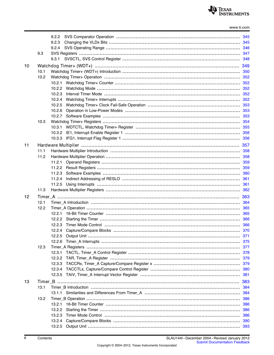
www.ti.com 9.3 9.2.2 SVS Comparator Operation ................................................................................... 345 9.2.3 Changing the VLDx Bits ........................................................................................ 345 9.2.4 SVS Operating Range .......................................................................................... 346 SVS Registers ............................................................................................................ 347 9.3.1 SVSCTL, SVS Control Register ............................................................................... 348 10 Watchdog Timer+ (WDT+) ................................................................................................. 349 10.1 Watchdog Timer+ (WDT+) Introduction ............................................................................... 350 10.2 Watchdog Timer+ Operation ........................................................................................... 352 10.2.1 Watchdog Timer+ Counter .................................................................................... 352 10.2.2 Watchdog Mode ................................................................................................ 352 10.2.3 Interval Timer Mode ........................................................................................... 352 10.2.4 Watchdog Timer+ Interrupts .................................................................................. 352 10.2.5 Watchdog Timer+ Clock Fail-Safe Operation .............................................................. 353 10.2.6 Operation in Low-Power Modes ............................................................................. 353 10.2.7 Software Examples ............................................................................................ 353 10.3 Watchdog Timer+ Registers ............................................................................................ 354 10.3.1 WDTCTL, Watchdog Timer+ Register ...................................................................... 355 10.3.2 IE1, Interrupt Enable Register 1 ............................................................................. 356 10.3.3 IFG1, Interrupt Flag Register 1 ............................................................................... 356 Hardware Multiplier .......................................................................................................... 357 11.1 Hardware Multiplier Introduction ....................................................................................... 358 11.2 Hardware Multiplier Operation .......................................................................................... 358 11.2.1 Operand Registers ............................................................................................. 359 11.2.2 Result Registers ................................................................................................ 359 11.2.3 Software Examples ............................................................................................ 360 11.2.4 Indirect Addressing of RESLO ............................................................................... 361 11.2.5 Using Interrupts ................................................................................................ 361 11.3 Hardware Multiplier Registers .......................................................................................... 362 Timer_A .......................................................................................................................... 363 Timer_A Introduction .................................................................................................... 364 12.1 Timer_A Operation ....................................................................................................... 365 12.2 12.2.1 16-Bit Timer Counter .......................................................................................... 365 12.2.2 Starting the Timer .............................................................................................. 366 12.2.3 Timer Mode Control ........................................................................................... 366 12.2.4 Capture/Compare Blocks ..................................................................................... 370 12.2.5 Output Unit ...................................................................................................... 371 12.2.6 Timer_A Interrupts ............................................................................................. 375 Timer_A Registers ....................................................................................................... 377 12.3.1 TACTL, Timer_A Control Register ........................................................................... 378 12.3.2 TAR, Timer_A Register ....................................................................................... 379 12.3.3 TACCRx, Timer_A Capture/Compare Register x .......................................................... 379 12.3.4 TACCTLx, Capture/Compare Control Register ............................................................ 380 12.3.5 TAIV, Timer_A Interrupt Vector Register ................................................................... 381 Timer_B .......................................................................................................................... 383 Timer_B Introduction .................................................................................................... 384 13.1 13.1.1 Similarities and Differences From Timer_A ................................................................ 384 Timer_B Operation ....................................................................................................... 386 13.2.1 16-Bit Timer Counter .......................................................................................... 386 13.2.2 Starting the Timer .............................................................................................. 386 13.2.3 Timer Mode Control ........................................................................................... 386 13.2.4 Capture/Compare Blocks ..................................................................................... 390 13.2.5 Output Unit ...................................................................................................... 393 13.2 12.3 11 12 13 6 Contents Copyright © 2004–2012, Texas Instruments Incorporated SLAU144I– December 2004–Revised January 2012 Submit Documentation Feedback
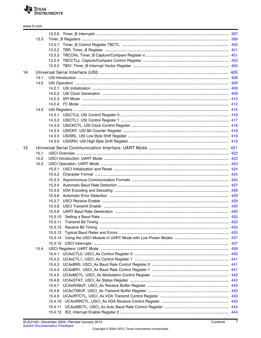
www.ti.com 14 15 13.3 13.2.6 Timer_B Interrupts ............................................................................................. 397 Timer_B Registers ....................................................................................................... 399 13.3.1 Timer_B Control Register TBCTL ........................................................................... 400 13.3.2 TBR, Timer_B Register ....................................................................................... 401 13.3.3 TBCCRx, Timer_B Capture/Compare Register x .......................................................... 401 13.3.4 TBCCTLx, Capture/Compare Control Register ............................................................ 402 13.3.5 TBIV, Timer_B Interrupt Vector Register ................................................................... 403 Universal Serial Interface (USI) .......................................................................................... 405 14.1 USI Introduction .......................................................................................................... 406 14.2 USI Operation ............................................................................................................ 409 14.2.1 USI Initialization ................................................................................................ 409 14.2.2 USI Clock Generation ......................................................................................... 409 14.2.3 SPI Mode ....................................................................................................... 410 14.2.4 I2C Mode ........................................................................................................ 412 14.3 USI Registers ............................................................................................................. 415 14.3.1 USICTL0, USI Control Register 0 ............................................................................ 416 14.3.2 USICTL1, USI Control Register 1 ............................................................................ 417 14.3.3 USICKCTL, USI Clock Control Register .................................................................... 418 14.3.4 USICNT, USI Bit Counter Register .......................................................................... 418 14.3.5 USISRL, USI Low Byte Shift Register ....................................................................... 419 14.3.6 USISRH, USI High Byte Shift Register ...................................................................... 419 Universal Serial Communication Interface, UART Mode ........................................................ 421 15.1 USCI Overview ........................................................................................................... 422 15.2 USCI Introduction: UART Mode ........................................................................................ 422 15.3 USCI Operation: UART Mode .......................................................................................... 424 15.3.1 USCI Initialization and Reset ................................................................................. 424 15.3.2 Character Format .............................................................................................. 424 15.3.3 Asynchronous Communication Formats .................................................................... 424 15.3.4 Automatic Baud Rate Detection .............................................................................. 427 15.3.5 IrDA Encoding and Decoding ................................................................................ 428 15.3.6 Automatic Error Detection .................................................................................... 429 15.3.7 USCI Receive Enable ......................................................................................... 429 15.3.8 USCI Transmit Enable ........................................................................................ 430 15.3.9 UART Baud Rate Generation ................................................................................ 430 15.3.10 Setting a Baud Rate .......................................................................................... 432 15.3.11 Transmit Bit Timing ........................................................................................... 433 15.3.12 Receive Bit Timing ........................................................................................... 433 15.3.13 Typical Baud Rates and Errors ............................................................................. 435 15.3.14 Using the USCI Module in UART Mode with Low Power Modes ...................................... 437 15.3.15 USCI Interrupts ............................................................................................... 437 15.4 USCI Registers: UART Mode .......................................................................................... 439 15.4.1 UCAxCTL0, USCI_Ax Control Register 0 .................................................................. 440 15.4.2 UCAxCTL1, USCI_Ax Control Register 1 .................................................................. 441 15.4.3 UCAxBR0, USCI_Ax Baud Rate Control Register 0 ...................................................... 441 15.4.4 UCAxBR1, USCI_Ax Baud Rate Control Register 1 ...................................................... 441 15.4.5 UCAxMCTL, USCI_Ax Modulation Control Register ...................................................... 442 15.4.6 UCAxSTAT, USCI_Ax Status Register ..................................................................... 442 15.4.7 UCAxRXBUF, USCI_Ax Receive Buffer Register ......................................................... 443 15.4.8 UCAxTXBUF, USCI_Ax Transmit Buffer Register ......................................................... 443 15.4.9 UCAxIRTCTL, USCI_Ax IrDA Transmit Control Register ................................................ 443 15.4.10 UCAxIRRCTL, USCI_Ax IrDA Receive Control Register ............................................... 443 15.4.11 UCAxABCTL, USCI_Ax Auto Baud Rate Control Register ............................................. 444 15.4.12 IE2, Interrupt Enable Register 2 ............................................................................ 444 SLAU144I– December 2004–Revised January 2012 Submit Documentation Feedback Copyright © 2004–2012, Texas Instruments Incorporated Contents 7
16 17 www.ti.com 15.4.13 IFG2, Interrupt Flag Register 2 ............................................................................. 444 15.4.14 UC1IE, USCI_A1 Interrupt Enable Register .............................................................. 445 15.4.15 UC1IFG, USCI_A1 Interrupt Flag Register ............................................................... 445 Universal Serial Communication Interface, SPI Mode ........................................................... 447 16.1 USCI Overview ........................................................................................................... 448 16.2 USCI Introduction: SPI Mode ........................................................................................... 448 16.3 USCI Operation: SPI Mode ............................................................................................. 450 16.3.1 USCI Initialization and Reset ................................................................................. 450 16.3.2 Character Format .............................................................................................. 451 16.3.3 Master Mode .................................................................................................... 451 16.3.4 Slave Mode ..................................................................................................... 452 16.3.5 SPI Enable ...................................................................................................... 453 16.3.6 Serial Clock Control ........................................................................................... 453 16.3.7 Using the SPI Mode With Low-Power Modes .............................................................. 454 16.3.8 SPI Interrupts ................................................................................................... 454 16.4 USCI Registers: SPI Mode ............................................................................................. 456 16.4.1 UCAxCTL0, USCI_Ax Control Register 0, UCBxCTL0, USCI_Bx Control Register 0 ................ 457 16.4.2 UCAxCTL1, USCI_Ax Control Register 1, UCBxCTL1, USCI_Bx Control Register 1 ................ 457 16.4.3 UCAxBR0, USCI_Ax Bit Rate Control Register 0, UCBxBR0, USCI_Bx Bit Rate Control Register 0 ................................................................................................................... 458 16.4.4 UCAxBR1, USCI_Ax Bit Rate Control Register 1, UCBxBR1, USCI_Bx Bit Rate Control Register 1 ................................................................................................................... 458 16.4.5 UCAxSTAT, USCI_Ax Status Register, UCBxSTAT, USCI_Bx Status Register ...................... 458 16.4.6 UCAxRXBUF, USCI_Ax Receive Buffer Register, UCBxRXBUF, USCI_Bx Receive Buffer Register .......................................................................................................... 458 16.4.7 UCAxTXBUF, USCI_Ax Transmit Buffer Register, UCBxTXBUF, USCI_Bx Transmit Buffer Register .......................................................................................................... 459 16.4.8 IE2, Interrupt Enable Register 2 ............................................................................. 459 16.4.9 IFG2, Interrupt Flag Register 2 ............................................................................... 459 16.4.10 UC1IE, USCI_A1/USCI_B1 Interrupt Enable Register .................................................. 460 16.4.11 UC1IFG, USCI_A1/USCI_B1 Interrupt Flag Register ................................................... 460 Universal Serial Communication Interface, I2C Mode ............................................................ 461 17.1 USCI Overview ........................................................................................................... 462 17.2 USCI Introduction: I2C Mode ........................................................................................... 462 17.3 USCI Operation: I2C Mode .............................................................................................. 463 17.3.1 USCI Initialization and Reset ................................................................................. 464 17.3.2 I2C Serial Data .................................................................................................. 464 17.3.3 I2C Addressing Modes ......................................................................................... 465 17.3.4 I2C Module Operating Modes ................................................................................. 466 17.3.5 I2C Clock Generation and Synchronization ................................................................. 476 17.3.6 Using the USCI Module in I2C Mode with Low-Power Modes ........................................... 477 17.3.7 USCI Interrupts in I2C Mode .................................................................................. 477 17.4 USCI Registers: I2C Mode .............................................................................................. 479 17.4.1 UCBxCTL0, USCI_Bx Control Register 0 .................................................................. 480 17.4.2 UCBxCTL1, USCI_Bx Control Register 1 .................................................................. 481 17.4.3 UCBxBR0, USCI_Bx Baud Rate Control Register 0 ...................................................... 481 17.4.4 UCBxBR1, USCI_Bx Baud Rate Control Register 1 ...................................................... 481 17.4.5 UCBxSTAT, USCI_Bx Status Register ..................................................................... 482 17.4.6 UCBxRXBUF, USCI_Bx Receive Buffer Register ......................................................... 482 17.4.7 UCBxTXBUF, USCI_Bx Transmit Buffer Register ......................................................... 482 17.4.8 UCBxI2COA, USCIBx I2C Own Address Register ......................................................... 483 17.4.9 UCBxI2CSA, USCI_Bx I2C Slave Address Register ...................................................... 483 17.4.10 UCBxI2CIE, USCI_Bx I2C Interrupt Enable Register .................................................... 483 17.4.11 IE2, Interrupt Enable Register 2 ............................................................................ 484 8 Contents Copyright © 2004–2012, Texas Instruments Incorporated SLAU144I– December 2004–Revised January 2012 Submit Documentation Feedback
分享到:
收藏