中国科技论文在线
http://www.paper.edu.cn
LED Power Optimization and Angle Parameters Analysis
for Indoor Visible Light Communication Systems
DING Yingrui, LI Lihua**
(School of Information and Communication Engineering, Beijing University of Posts and
Telecommunications, Beijing 100876)
Abstract: The transmit power and half power semi-angle (HPSA) of LEDs as well as receiver's field of
view (FOV) affect the performance of indoor visible light communication systems. In this paper, a
novel linear programming (LP) method is proposed to optimize transmit power of LEDs. System
performance with different HPSA and FOV is also investigated. Simulation results show that a
significant improvement of illumination and communication quality as well as a remarkable reduction
of power consumption is achieved after the proposed LP optimization. What's more, the influence of
various HPSA and FOV on VLC system is found to be double-sided.
Key words: visible light communication; power allocation; linear programming
0 Introduction
Visible light communication is receiving increasing attention nowadays due to the trend
toward solid state lighting[1]-[4]. However, the performance of a VLC system is often not
satisfactory due to reasons such as inter-symbol interference (ISI), fluctuation of received signal
power and illuminance. The performance is affected by multiple factors, such as LEDs' transmit
power and HPSA as well as receivers' FOV. Therefore it is necessary to optimize these parameters
to obtain satisfactory communication and illuminance performance for users at different position
within the room environment.
Recently, much work has been done on optimizing VLC system parameters. A novel genetic
algorithm is utilized to optimize transmit power of a large number of LEDs[5]. However, this
method is flawed in complexity and accuracy of result. Receiver's FOV and its effect on
communication data rate is analyzed[6]. It is shown that high data rate is achievable with a small
receiver FOV. But the illuminance performance is not considered which is important for VLC
systems. The optimization of HPSA of LEDs is investigated to improve transmission bandwidth[7].
A VLC system employing spotlight is analyzed which shows that using a narrow HPSA enables
high data rate and low channel distortion[8]. Generally, these analysis focus on a single parameter
and some optimization scheme is not efficient. To improve system performance further and more
efficiently, we need to take multiple factors that affects system performance into consideration and
5
10
15
20
25
30
35
find better methods to optimize system parameters.
In this paper, we apply a novel linear programming method to optimize the transmit power of
every LED. After that, we analyze VLC system performance with different HPSA and FOV. The
VLC system performance is evaluated using the fluctuation of received power, uniformity
illuminance ratio (UIR), mean rms delay spread and system power consumption.
40
1 System Model
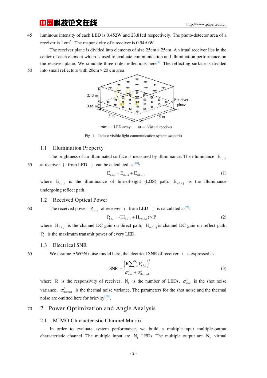
An indoor visible light communication scenario is shown in Fig. 1. A room with size of
5m 5m 3m was used. The reflectivity of walls, ceiling and floor is 0.5, 0.8 and 0.2 respectively.
Sixteen LED arrays are uniformly distributed on the ceiling[5]. Each LED array is filled with
49(7 7) LEDs. The space between LEDs is 4cm. The initial transmitted power and center
Brief author introduction:丁颖睿 (1990-),男,硕士研究生,主要研究方向:室内可见光通信
Correspondance author: 李立华(1976-),女,副教授,主要研究方向:室内可见光通信,MIMO 技术,中
继和协作通信. E-mail: lilihua@bupt.edu.cn
- 1 -
�
中国科技论文在线
http://www.paper.edu.cn
45
luminous intensity of each LED is 0.452W and 23.81cd respectively. The photo-detector area of a
receiver is 1
. The responsivity of a receiver is 0.54A/W.
The receiver plane is divided into elements of size 25cm 25cm. A virtual receiver lies in the
center of each element which is used to evaluate communication and illumination performance on
the receiver plane. We simulate three order reflections here[9]. The reflecting surface is divided
into small reflectors with 20cm 20 cm area.
50
Fig. 1 Indoor visible light communication system scenario
1.1
Illumination Property
The brightness of an illuminated surface is measured by illuminance. The illuminance
55
at receiver
from LED
can be calculated as[10]:
(1)
where
is the illuminance of line-of-sight (LOS) path.
is the illuminance
undergoing reflect path.
1.2 Received Optical Power
60
The received power
at receiver
from LED
is calculated as[9]:
(2)
where
is the channel DC gain on direct path,
is channel DC gain on reflect path,
is the maximum transmit power of every LED.
1.3 Electrical SNR
65
We assume AWGN noise model here, the electrical SNR of receiver
is expressed as:
(3)
where
is the responsivity of receiver,
is the number of LEDs,
is the shot noise
variance,
noise are omitted here for brievity[10].
is the thermal noise variance. The parameters for the shot noise and the thermal
70
2 Power Optimization and Angle Analysis
2.1 MIMO Characteristic Channel Matrix
In order to evaluate system performance, we build a multiple-input multiple-output
characteristic channel. The multiple input are
LEDs. The multiple output are
virtual
- 2 -
2cm,,rijEij,,,,,,rijdijrefijEEE,,dijE,,refijE,,rijPij,,,,,,()rijdijrefijlPHHP,,dijH,,refijHlPi2,,122tNrijjishotthermalRPSNRRtN2shot2thermaltNrN�
中国科技论文在线
http://www.paper.edu.cn
receivers. So the illuminance channel can be expressed as:
75
(4)
where
is the illuminance from LED
to receiver
using Eq. (1). The
received illuminance of virtual receivers is:
(5)
where
is the scaling vector for LEDs.
80
Similarly, the power channel is defined as:
(6)
where
is the channel DC gain from LED
to receiver
. It can be
calculated using Eq. (2). The received power of all virtual receivers is:
(7)
85
where
is the transmitted optical power vector,
is the received power vector.
2.2 LED Power Optimization
The transmitted power of every LED is optimized by a scaling factor
,
. The
corresponding scaling vector for all LEDs is
. As a result, the transmitted
optical power vector
,
.
90
Communication performance is one of the key factors to be considered when designing a
VLC system. We use a fixed target power vector
(8)
to represent the minimum received power for
virtual receivers. The target power
is
predefined according to the communication requirements of different receivers.
95
A minimum illuminance vector is applied to ensure the illumination requirements is satisfied
according to illumination standards. The received illuminance of a virtual receiver should be
larger than the minimum illuminance. For all
receivers, the target illumination vector is
(9)
The values for
and
can be modified to adjust to different illumination and
100
communication requirement flexibly. Then we minimize the gap between actual received power
and the target power vector
as well as the gap between
and the target illuminance
vector
, that is:
105
- 3 -
111212122212ttrrrtNNNNNNlllllllllL,,,,ijdijrefijlEEjilly=Lxlx111212122212ttrrrtNNNNNNhhhhhhhhhH,,,,ijdijrefijhHHjippy=Hxpxpyia01ia12[,,]tTNaaaalPpxalxa1[,,]tTppNbbpbrNpbrN1[,,]rTllNbblblbpbpypblylbmin11||||,||||lPplHabLabs.t.lPpHablLab�
中国科技论文在线
http://www.paper.edu.cn
,
(10)
where
is the maximum transmitted power of all LEDs. Using the linear scalarization method,
we transfer the problem as follows:
110
,
(11)
115
where
represents the mean value.
This optimization problem is a linear programming problem since the objective function and
the constrains are all linear in the scaling vector
. Linear programming problems have
polynomial-time solutions. The running time is
, where
is the number of bits in the
input[11]. As a comparison, the complexity of a full-search method is exponential, that is
,
120
where
is the number of all scaling levels.
2.3 System Performance with Different HPSA and FOV
The performance of a VLC system is influenced by LEDs' HPSA and receivers' FOV.
However it is difficult to find the optimal HPSA and FOV especially when considering reflections
of indoor objects. Here we use an exhaustive search method which is followed by the proposed LP
125
optimization method to investigate the influence of HPSA and FOV values on VLC systems.
We assume there are
discrete HPSA values and
FOV values. For all
HPSA
and FOV pairs, problem (11) is solved with fixed target power
and target illumination
.
Four indicators are utilized to evaluate system performance. Fluctuation of received power is
used to evaluate the uniformity of received power[5]. It is given by
.
130
UIR is used to judge illuminance performance. It is expressed as
. Channel
root mean square delay spread is used to measure ISI [10]. Power consumption is also used as the
last indicator.
3 System Performance
We assume 500Mb/s data rate for each position within the indoor environment. OOK-NRZ
135
modulation scheme is used. Modulated OOK signal has rectangular pulse with duration equal to
the bit period. The receiver filter has a raised-cosine spectrum with 100% excess bandwidth. To
ensure BER<
, SNR should be larger than 13.6dB. Using Eq. (3), the corresponding received
power is 1.97
W. To achieve uniform performance in all positions, each element in the
target power vector is set to be
=1.97
,
. According to standards of ISO,
140
illuminance of 300lx to 1500lx is needed for office work, we set
=400,
.
3.1 Optimized and Non-optimized System Performance
In this part, the optimized and non-optimized system performance is compared. LEDs' HPSA
- 4 -
01ia1,,tiN1tNiallliaPPallPmin11||||||||()()lPEEplplHabLabbbs.t.lPpHablLab01ia1,,tiN1tNiallliaPP()Ea3.52()tONkkStNSMKMKpblb(max()min())/max()pppyyymin()/mean()llyy610510pib5101,,riNlib1,,riN�
中国科技论文在线
is 80 degree and receivers' FOV is 55 degree[5].
http://www.paper.edu.cn
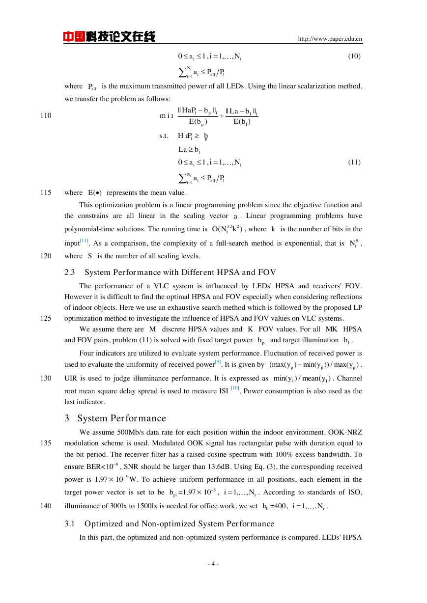
The non-optimized received power varies between -4.59 dBm and -0.70dBm as in Fig. 2(a).
145
Fig. 2(b) shows the optimized power distribution using linear programming, varying between
-9.97dBm and -8.54dBm. Comparing with the non-optimized case, fluctuation of received power
drop from 59.1% to 28.0% after LP optimization. It equals to a 31.1% decrease. The
non-optimized illuminance is shown in Fig. 2(c), varies between 1612.6lx and 2360.5lx. Fig. 2(d)
shows the optimized illuminance LP, varies between 400lx and 453.0lx. The uniformity
150
illuminance ratio is improved from 0.78 to 0.94 after optimization meanwhile the illuminance is
sufficient for indoor lighting. In Fig. 2(e), the average rms delay spread without optimization is
1.68ns, the minimum and maximum rms delay spread is 1.34ns and 2.14ns respectively. After LP
optimization, the average rms delay spread is 1.49ns, the minimum and maximum rms delay
spread is 0.90ns and 1.99ns as in Fig. 2(f). What's more, system power consumption drop from
155
354.4W to 80.5W.
(a) (b)
(c) (d)
(e) (f)
Fig. 2. Performance comparison of non-optimized case, and linear programming.
(a) Non-optimized received power. (b) Optimized received power using LP. (c) Non-optimized illuminance.
(d) Optimized illuminance using LP. (e) Non-optimized rms delay spread. (f) Optimized rms delay spread.
3.2 HPSA,FOV and System Performance
Based on the proposed LP optimization method, we analyze system performance with
different HPSA and FOV. The HPSA varies between 25 degree and 90 degree and the FOV varies
- 5 -
160
165
�
中国科技论文在线
http://www.paper.edu.cn
between 10 degree and 60 degree, both with an interval of 5 degree.
170
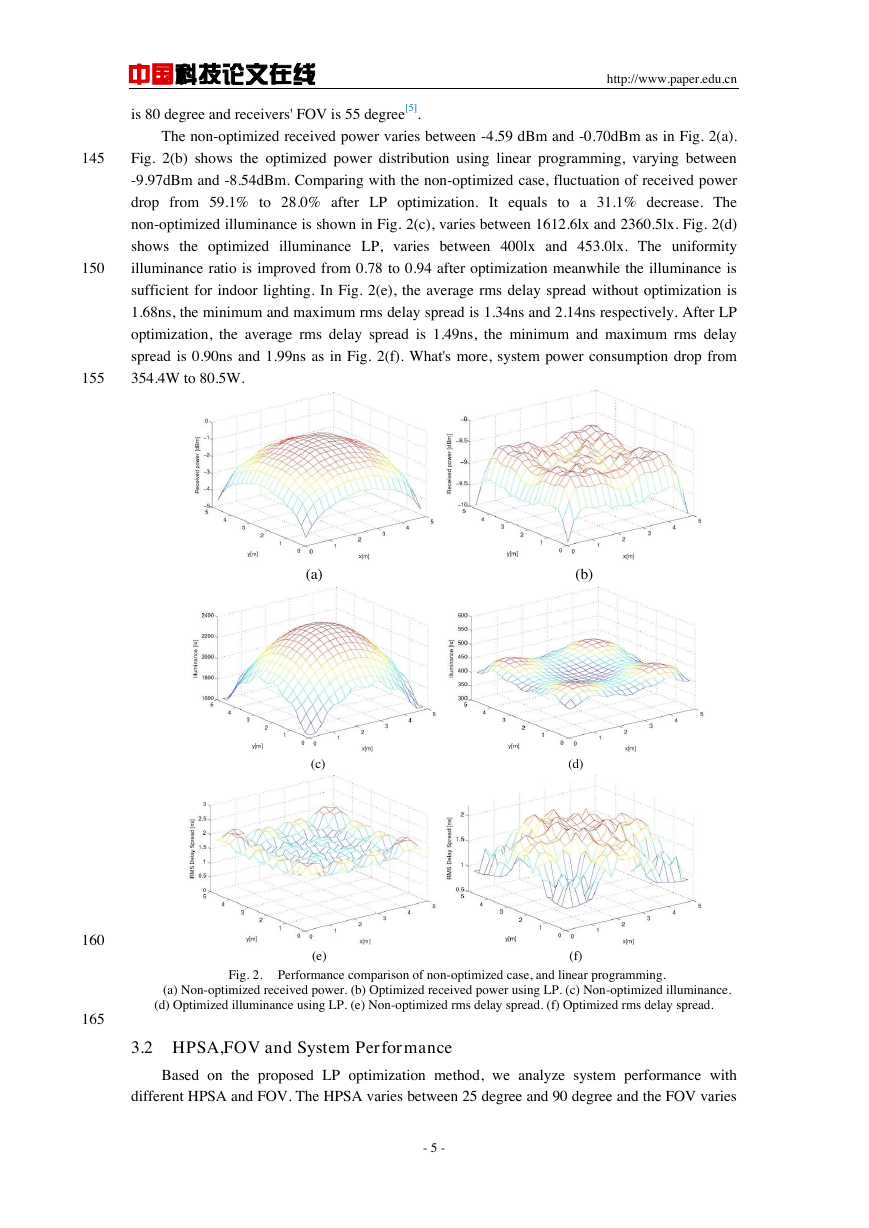
In Fig. 3(a), as LEDs' HPSA increase, the fluctuation of received power shows different
trends. When FOV is between 30 degree and 45 degree, power fluctuation is high due to a tradeoff
between uniform power and illuminance. When FOV varies from 50 degree to 60 degree, received
power fluctuation is small. UIR performance is shown in Fig.3(b). Since the UIR should be over
0.7 [10], the illuminance performance is satisfactory after LP optimization regardless of LED HPSA
and receiver FOV. Fig. 3(c) shows average rms delay spread performance. The average rms delay
175
spread will increase when FOV or HPSA grow wider. So narrow HPSA and FOV is helpful for
reducing multipath induced ISI. Fig. 3(d) shows system power consumed. The power demand
drops quickly as HPSA increase. The large power consumption when receivers' FOV is small is
caused by the decrease of received power of a receiver.
180
The results show that a wide LED HPSA can reduce power consumption significantly at the
cost of increased inter-symbol interference. A narrow FOV reduces multipath components
however the received signal power is not stable at different locations which degrades
communication quality.
185
(a) (b)
(c) (d)
190
Fig. 3. System performance with different HPSA and FOV. (a) Fluctuation of received power. (b)
Uniformity illuminance ratio. (c) Average RMS delay spread. (d) System power consumption.
4 Conclusion
In this paper, we propose a linear programming method to optimize the transmit power of
LEDs considering both communication and illumination. Compared with the non-optimized case,
195
fluctuation of received power decrease to a large extent, all users within the room can have almost
identical communication quality. The UIR is improved which enables more uniform illuminance
distribution. The average rms delay spread is reduced which alleviates the performance loss due to
multipath propagation. The system power consumption also drops significantly after the proposed
optimization. The influence of LED HPSA and receiver FOV on VLC systems is also investigated.
- 6 -
�
中国科技论文在线
http://www.paper.edu.cn
200
It is also shown that a wide LED HPSA enables lower power consumption however at the cost of
increased inter-symbol interference. A narrow FOV can reduce received multipath components
but lead to unstable communication quality at different indoor locations.
References
205
210
215
220
225
230
235
240
[1] T. Fath and H. Haas. Performance comparison of mimo techniques for optical wireless communications in
indoor environments[J]. IEEE Trans. Commun, 2013, 61(2): 733-742.
[2] M. Biagi, T. Borogovac, and T. Little. Adaptive receiver for indoor visible light communications[J]. Lightwave
Technology, Journal of, 2013, 31(23):3676-3686.
[3] I. Stefan and H. Haas. Analysis of optimal placement of led arrays for visible light communication. Vehicular
Technology Conference (VTC Spring), 2013, 1-5.
[4] L. Zeng, D. C. O'Brien, H. L. Minh, G. E. Faulkner, K. Lee, D. Jung, Y.Oh, and E. T. Won. High data rate
multiple input multiple output (MIMO) optical wireless communications using white led lighting[J]. IEEE J. Select.
Areas Commun., 2009, 27(9):1654-1662.
[5] J. Ding, Z. Huang, and Y. Ji. Evolutionary algorithm based power coverage optimization for visible light
communications[J]. IEEE Commun. Lett., 2012 ,16(4):439-441
[6] T. Komine and M. Nakagawa. Fundamental analysis for visible-light communication system using led lights[J].
IEEE Trans. Consum. Electron., 2004, 50(1):100-107
[7] D. Wu, Z. Ghassemlooy, H. Le Minh, S. Rajbhandari, M. khalighi, and X. Tang. Optimization of lambertian
order for indoor non-directed optical wireless communication. Communications in China Workshops (ICCC),
2012 1st IEEE International Conference on, 2012, 43-48
[8] T. Borogovac, M. Rahaim, and J. B. Carruthers. Spotlighting for visible light communications and illumination.
Globecom Workshop, 2010, 1077-1081.
[9] Alqudah, Y. A. and Kavehrad, Mohsen. MIMO characterization of indoor wireless optical link using a
diffuse-transmission configuration[J]. Communications, IEEE Transactions on, 2013, 51(9):1554-1560.
[10] Komine, T. and Lee, J. H. and Haruyama, S. and Nakagawa, M. Adaptive equalization system for visible light
wireless communication utilizing multiple white LED lighting equipment[J]. Wireless Communications, IEEE
Transactions on, 2009, 8(6):2892-2900.
[11] N. Karmarkar. A new polynomial-time algorithm for linear programming. Proceedings of the Sixteenth
Annual ACM Symposium on Theory of Computing, ser. STOC'84, 1984, 302-311.
室内可见光通信系统 LED 灯源功率优
化及角度参数分析
丁颖睿,李立华
(北京邮电大学信息与通信工程学院,北京 100876)
摘要:室内可见光通信系统的性能受到 LED 灯源发送功率,LED 灯源半功率角(HPSA)
以及接收器视角(FOV)的影响。本文提出了一种新颖的线性规划优化方法来优化 LED 灯
源发射功率,此外分析了不同 LED 半功率角,不同接收器视角对系统通信,照明性能的影
响。仿真结果表明采用本文优化算法,系统照明和通信质量有显著提升,同时系统消耗的功
率显著下降,此外,仿真结果还表明 LED 灯源半功率角,接收器视角对可见光通信系统性
能的影响是双面的,需要权衡。
关键词:可见光通信;功率分配;线性规划
中图分类号:TN929.12
- 7 -
�


 2023年江西萍乡中考道德与法治真题及答案.doc
 2012年重庆南川中考生物真题及答案.doc
 2013年江西师范大学地理学综合及文艺理论基础考研真题.doc
 2020年四川甘孜小升初语文真题及答案I卷.doc
 2020年注册岩土工程师专业基础考试真题及答案.doc
 2023-2024学年福建省厦门市九年级上学期数学月考试题及答案.doc
 2021-2022学年辽宁省沈阳市大东区九年级上学期语文期末试题及答案.doc
 2022-2023学年北京东城区初三第一学期物理期末试卷及答案.doc
 2018上半年江西教师资格初中地理学科知识与教学能力真题及答案.doc
 2012年河北国家公务员申论考试真题及答案-省级.doc
 2020-2021学年江苏省扬州市江都区邵樊片九年级上学期数学第一次质量检测试题及答案.doc
 2022下半年黑龙江教师资格证中学综合素质真题及答案.doc