logo资料库

pcie_3.0_规范.pdf

第1页 / 共860页
第2页 / 共860页
第3页 / 共860页
第4页 / 共860页
第5页 / 共860页
第6页 / 共860页
第7页 / 共860页
第8页 / 共860页
资料共860页,剩余部分请下载后查看
PCI Express Base Specification, Revision 3.0
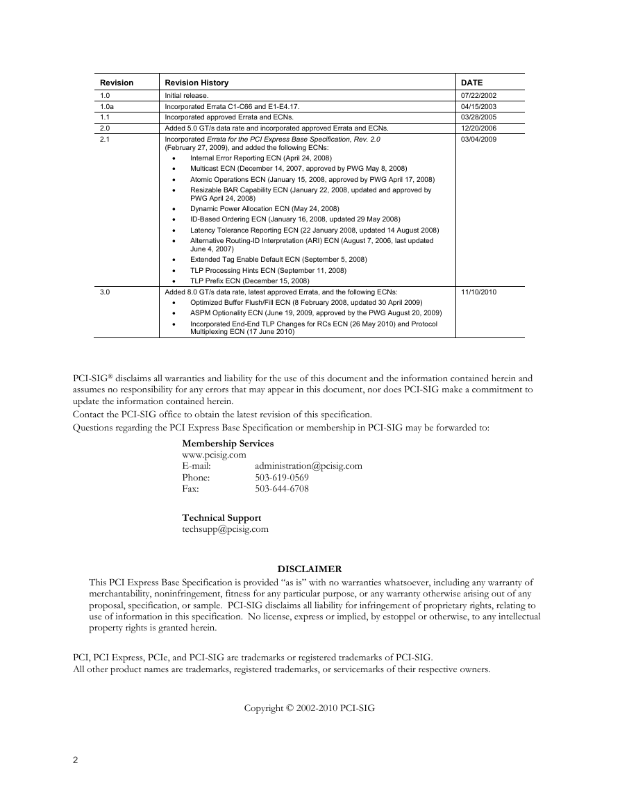
Revision History
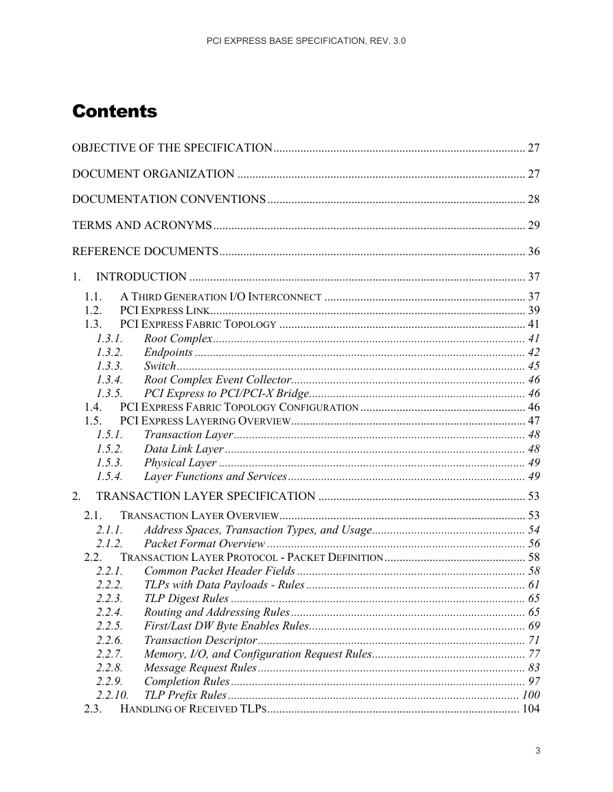
Contents
Objective of the Specification
Document Organization
Documentation Conventions
Terms and Acronyms
Reference Documents
1. Introduction
1.1. A Third Generation I/O Interconnect
1.2. PCI Express Link
1.3. PCI Express Fabric Topology
1.3.1. Root Complex
1.3.2. Endpoints
1.3.2.1. Legacy Endpoint Rules
1.3.2.2. PCI Express Endpoint Rules
1.3.2.3. Root Complex Integrated Endpoint Rules
1.3.3. Switch
1.3.4. Root Complex Event Collector
1.3.5. PCI Express to PCI/PCI-X Bridge
1.4. PCI Express Fabric Topology Configuration
1.5. PCI Express Layering Overview
1.5.1. Transaction Layer
1.5.2. Data Link Layer
1.5.3. Physical Layer
1.5.4. Layer Functions and Services
1.5.4.1. Transaction Layer Services
1.5.4.2. Data Link Layer Services
1.5.4.3. Physical Layer Services
1.5.4.4. Inter-Layer Interfaces
1.5.4.4.1. Transaction/Data Link Interface
1.5.4.4.2. Data Link/Physical Interface
2. Transaction Layer Specification
2.1. Transaction Layer Overview
2.1.1. Address Spaces, Transaction Types, and Usage
2.1.1.1. Memory Transactions
2.1.1.2. I/O Transactions
2.1.1.3. Configuration Transactions
2.1.1.4. Message Transactions
2.1.2. Packet Format Overview
2.2. Transaction Layer Protocol - Packet Definition
2.2.1. Common Packet Header Fields
2.2.2. TLPs with Data Payloads - Rules
2.2.3. TLP Digest Rules
2.2.4. Routing and Addressing Rules
2.2.4.1. Address Based Routing Rules
2.2.4.2. ID Based Routing Rules
2.2.5. First/Last DW Byte Enables Rules
2.2.6. Transaction Descriptor
2.2.6.1. Overview
2.2.6.2. Transaction Descriptor – Transaction ID Field
2.2.6.3. Transaction Descriptor – Attributes Field
2.2.6.4. Relaxed Ordering and ID-Based Ordering Attributes
2.2.6.5. No Snoop Attribute
2.2.6.6. Transaction Descriptor – Traffic Class Field
2.2.7. Memory, I/O, and Configuration Request Rules
2.2.7.1. TPH Rules
2.2.8. Message Request Rules
2.2.8.1. INTx Interrupt Signaling - Rules
2.2.8.2. Power Management Messages
2.2.8.3. Error Signaling Messages
2.2.8.4. Locked Transactions Support
2.2.8.5. Slot Power Limit Support
2.2.8.6. Vendor_Defined Messages
2.2.8.7. Ignored Messages
2.2.8.8. Latency Tolerance Reporting (LTR) Message
2.2.8.9. Optimized Buffer Flush/Fill (OBFF) Message
2.2.9. Completion Rules
2.2.10. TLP Prefix Rules
2.2.10.1. Local TLP Prefix Processing
2.2.10.1.1. Vendor Defined Local TLP Prefix
2.2.10.2. End-End TLP Prefix Processing
2.2.10.2.1. Vendor Defined End-End TLP Prefix
2.2.10.2.2. Root Ports with End-End TLP Prefix Supported
2.3. Handling of Received TLPs
2.3.1. Request Handling Rules
2.3.1.1. Data Return for Read Requests
2.3.2. Completion Handling Rules
2.4. Transaction Ordering
2.4.1. Transaction Ordering Rules
2.4.2. Update Ordering and Granularity Observed by a Read Transaction
2.4.3. Update Ordering and Granularity Provided by a Write Transaction
2.5. Virtual Channel (VC) Mechanism
2.5.1. Virtual Channel Identification (VC ID)
2.5.2. TC to VC Mapping
2.5.3. VC and TC Rules
2.6. Ordering and Receive Buffer Flow Control
2.6.1. Flow Control Rules
2.6.1.1. FC Information Tracked by Transmitter
2.6.1.2. FC Information Tracked by Receiver
2.7. Data Integrity
2.7.1. ECRC Rules
2.7.2. Error Forwarding
2.7.2.1. Error Forwarding Usage Model
2.7.2.2. Rules For Use of Data Poisoning
2.8. Completion Timeout Mechanism
2.9. Link Status Dependencies
2.9.1. Transaction Layer Behavior in DL_Down Status
2.9.2. Transaction Layer Behavior in DL_Up Status
3. Data Link Layer Specification
3.1. Data Link Layer Overview
3.2. Data Link Control and Management State Machine
3.2.1. Data Link Control and Management State Machine Rules
3.3. Flow Control Initialization Protocol
3.3.1. Flow Control Initialization State Machine Rules
3.4. Data Link Layer Packets (DLLPs)
3.4.1. Data Link Layer Packet Rules
3.5. Data Integrity
3.5.1. Introduction
3.5.2. LCRC, Sequence Number, and Retry Management (TLP Transmitter)
3.5.2.1. LCRC and Sequence Number Rules (TLP Transmitter)
3.5.2.2. Handling of Received DLLPs
3.5.3. LCRC and Sequence Number (TLP Receiver)
3.5.3.1. LCRC and Sequence Number Rules (TLP Receiver)
4. Physical Layer Specification
4.1. Introduction
4.2. Logical Sub-block
4.2.1. Encoding for 2.5 GT/s and 5.0 GT/s Data Rates
4.2.1.1. Symbol Encoding
4.2.1.1.1. Serialization and De-serialization of Data
4.2.1.1.2. Special Symbols for Framing and Link Management (K Codes)
4.2.1.1.3. 8b/10b Decode Rules
4.2.1.2. Framing and Application of Symbols to Lanes
4.2.1.3. Data Scrambling
4.2.2. Encoding for 8.0 GT/s and Higher Data Rates
4.2.2.1. Lane Level Encoding
4.2.2.2. Ordered Set Blocks
4.2.2.2.1. Block Alignment
4.2.2.3. Data Blocks
4.2.2.3.1. Framing Tokens
4.2.2.3.2. Transmitter Framing Requirements
4.2.2.3.3. Receiver Framing Requirements
4.2.2.3.4. Recovery from Framing Errors
4.2.2.4. Scrambling
4.2.2.5. Loopback with 128b/130b Code
4.2.3. Link Equalization Procedure for 8.0 GT/s Data Rate
4.2.3.1. Rules for Transmitter Coefficients
4.2.3.2. Encoding of Presets
4.2.4. Link Initialization and Training
4.2.4.1. Training Sequences
4.2.4.2. Electrical Idle Sequences
4.2.4.3. Inferring Electrical Idle
4.2.4.4. Lane Polarity Inversion
4.2.4.5. Fast Training Sequence (FTS)
4.2.4.6. Start of Data Stream Ordered Set
4.2.4.7. Link Error Recovery
4.2.4.8. Reset
4.2.4.8.1. Fundamental Reset
4.2.4.8.2. Hot Reset
4.2.4.9. Link Data Rate Negotiation
4.2.4.10. Link Width and Lane Sequence Negotiation
4.2.4.10.1. Required and Optional Port Behavior
4.2.4.11. Lane-to-Lane De-skew
4.2.4.12. Lane vs. Link Training
4.2.5. Link Training and Status State Machine (LTSSM) Descriptions
4.2.5.1. Detect
4.2.5.2. Polling
4.2.5.3. Configuration
4.2.5.4. Recovery
4.2.5.5. L0
4.2.5.6. L0s
4.2.5.7. L1
4.2.5.8. L2
4.2.5.9. Disabled
4.2.5.10. Loopback
4.2.5.11. Hot Reset
4.2.6. Link Training and Status State Rules
4.2.6.1. Detect
4.2.6.1.1. Detect.Quiet
4.2.6.1.2. Detect.Active
4.2.6.2. Polling
4.2.6.2.1. Polling.Active
4.2.6.2.2. Polling.Compliance
4.2.6.2.3. Polling.Configuration
4.2.6.2.4. Polling.Speed
4.2.6.3. Configuration
4.2.6.3.1. Configuration.Linkwidth.Start
4.2.6.3.1.1. Downstream Lanes
4.2.6.3.1.2. Upstream Lanes
4.2.6.3.2. Configuration.Linkwidth.Accept
4.2.6.3.2.1. Downstream Lanes
4.2.6.3.2.2. Upstream Lanes
4.2.6.3.3. Configuration.Lanenum.Accept
4.2.6.3.3.1. Downstream Lanes
4.2.6.3.3.2. Upstream Lanes
4.2.6.3.4. Configuration.Lanenum.Wait
4.2.6.3.4.1. Downstream Lanes
4.2.6.3.4.2. Upstream Lanes
4.2.6.3.5. Configuration.Complete
4.2.6.3.5.1. Downstream Lanes
4.2.6.3.5.2. Upstream Lanes
4.2.6.3.6. Configuration.Idle
4.2.6.4. Recovery
4.2.6.4.1. Recovery.RcvrLock
4.2.6.4.2. Recovery.Equalization
4.2.6.4.2.1 Downstream Lanes
4.2.6.4.2.1.1. Phase 1 of Transmitter Equalization
4.2.6.4.2.1.2. Phase 2 of Transmitter Equalization
4.2.6.4.2.1.3. Phase 3 of Transmitter Equalization
4.2.6.4.2.2 Upstream Lanes
4.2.6.4.2.2.1. Phase 0 of Transmitter Equalization
4.2.6.4.2.2.2. Phase 1 of Transmitter Equalization
4.2.6.4.2.2.3. Phase 2 of Transmitter Equalization
4.2.6.4.2.2.4. Phase 3 of Transmitter Equalization
4.2.6.4.3. Recovery.Speed
4.2.6.4.4. Recovery.RcvrCfg
4.2.6.4.5. Recovery.Idle
4.2.6.5. L0
4.2.6.6. L0s
4.2.6.6.1. Receiver L0s
4.2.6.6.1.1. Rx_L0s.Entry
4.2.6.6.1.2. Rx_L0s.Idle
4.2.6.6.1.3. Rx_L0s.FTS
4.2.6.6.2. Transmitter L0s
4.2.6.6.2.1. Tx_L0s.Entry
4.2.6.6.2.2. Tx_L0s.Idle
4.2.6.6.2.3. Tx_L0s.FTS
4.2.6.7. L1
4.2.6.7.1. L1.Entry
4.2.6.7.2. L1.Idle
4.2.6.8. L2
4.2.6.8.1. L2.Idle
4.2.6.8.2. L2.TransmitWake
4.2.6.9. Disabled
4.2.6.10. Loopback
4.2.6.10.1. Loopback.Entry
4.2.6.10.2. Loopback.Active
4.2.6.10.3. Loopback.Exit
4.2.6.11. Hot Reset
4.2.7. Clock Tolerance Compensation
4.2.7.1. SKP Ordered Set for 8b/10b Encoding
4.2.7.2. SKP Ordered Set for 128b/130b Encoding
4.2.7.3. Rules for Transmitters
4.2.7.4. Rules for Receivers
4.2.8. Compliance Pattern in 8b/10b Encoding
4.2.9. Modified Compliance Pattern in 8b/10b Encoding
4.2.10. Compliance Pattern in 128b/130b Encoding
4.2.11. Modified Compliance Pattern in 128b/130b Encoding
4.3. Electrical Sub-block
4.3.1. Electrical Specification Organization
4.3.2. Interoperability Criteria for 2.5, 5.0, and 8.0 GT/s Devices
4.3.2.1. 8.0 GT/s Standards Applied to 2.5 and 5.0 GT/s Devices
4.3.2.1.1. ESD Standards
4.3.2.1.2. Receiver Powered Off Resistance
4.3.2.1.3. Tx Equalization Tolerance
4.3.2.1.4. Tx Equalization During Tx Margining
4.3.2.1.5. VTX-ACCM and VRX-ACCM
4.3.2.2. 2.5 GT/s is Not a Subset of 5.0 GT/s and 5.0 GT/s is Not a Subset of 8.0 GT/s
4.3.2.3. Component Interfaces
4.3.3. Transmitter Specification
4.3.3.1. Transmitter Pin to Pad Correlation
4.3.3.1.1. Measurement Setup for Characterizing 2.5 GT/s and 5.0 GT/s Transmitters
4.3.3.1.2. Measurement Setup for Characterizing 8.0 GT/s Transmitters
4.3.3.1.3. 8.0 GT/s Breakout and Replica Channels
4.3.3.2. Voltage Level Definitions
4.3.3.2.1. 2.5 and 5.0 GT/s Specific Voltage Definitions
4.3.3.3. 2.5 and 5.0 GT/s Transmitter De-emphasis
4.3.3.4. Reduced Swing at 2.5 and 5.0 GT/s
4.3.3.5. 8.0 GT/s Tx Voltage Parameters
4.3.3.5.1. 8.0 GT/s Transmitter Equalization
4.3.3.5.2. Tx Equalization Presets
4.3.3.5.3. Method for Measuring VTX-FS-NO-EQ
4.3.3.5.4. Coefficient Range and Tolerance
4.3.3.5.5. EIEOS Pattern and VTX-EIEOS-FS and VTX-EIEOS-RS Limits
4.3.3.5.6. Reduced Swing Signaling
4.3.3.5.7. Effective Tx Package Loss
4.3.3.6. 5.0 GT/s Transmitter Margining
4.3.3.7. 8.0 GT/s Transmitter Margining
4.3.3.8. Jitter Budgeting and Measurement
4.3.3.9. 2.5 GT/s and 5.0 GT/s Transmitter Phase Jitter Filtering
4.3.3.9.1. Measuring Tx Eye Width in the Presence of De-Emphasis
4.3.3.10. 8.0 GT/s Tx Jitter Parameters
4.3.3.10.1. Data Dependent and Uncorrelated Jitter
4.3.3.10.2. Post Processing Steps to Extract Jitter
4.3.3.10.3. De-embedding
4.3.3.10.4. Behavioral CDR and Clock Recovery Algorithm
4.3.3.10.5. Data Dependent Jitter (TTX-DDJ)
4.3.3.10.6. Uncorrelated Total Jitter and Deterministic Jitter (TTX-UTJ and TTX-UDJDD)
4.3.3.10.7. Uncorrelated Total and Deterministic PWJ (TTX-UPW-TJ and TTX-UPW-DJDD)
4.3.3.11. Tx and Rx Return Loss
4.3.3.12. Transmitter PLL Bandwidth and Peaking
4.3.3.12.1. 2.5 GT/s and 5.0 GT/s Tx PLL Bandwidth and Peaking
4.3.3.12.2. 8.0 GT/s Tx PLL Bandwidth and Peaking
4.3.3.12.3. Series Capacitors
4.3.3.13. Common Transmitter Parameters
4.3.3.13.1. 8.0 GT/s Specific Tx Voltage and Jitter Parameter Table
4.3.4. Receiver Specifications
4.3.4.1. 2.5 GT/s and 5.0 GT/s Receiver Specification
4.3.4.1.1. Receiver Pin to Pad Correlation
4.3.4.1.2. Calibration Channel Characteristics
4.3.4.1.3. Receiver Tolerancing at 5.0 GT/s
4.3.4.1.4. 5.0 GT/s Receiver Compliance Eye Diagram
4.3.4.1.5. 5.0 GT/s Receiver Dynamic Voltage Range
4.3.4.2. 8.0 GT/s Receiver Stressed Eye Specification
4.3.4.3. Breakout and Replica Channels
4.3.4.3.1. Calibration Channels
4.3.4.3.2. Post Processing Procedures
4.3.4.3.3. Behavioral Rx Package Model
4.3.4.3.4. Behavioral CDR Model
4.3.4.3.5. Behavioral Rx Equalization Algorithms
4.3.4.3.6. Behavioral CTLE
4.3.4.3.7. Behavioral DFE
4.3.4.4. Stressed Voltage and Stressed Jitter Rx Tests
4.3.4.4.1. Procedure for Calibrating a Stressed Voltage Eye
4.3.4.4.2. Procedure for Testing Rx DUT for Stressed Voltage
4.3.4.4.3. Procedure for Calibrating a Stressed Jitter Eye
4.3.4.4.4. Testing Receivers for Stressed/Swept Jitter
4.3.4.4.5. Data Clocked and Common Refclk Rx Architectures
4.3.4.5. Common Receiver Parameters
4.3.4.5.1. 5.0 GT/s Exit From Idle Detect (EFI)
4.3.4.5.2. Receiver Loopback
4.3.4.5.3. Receiver Return Loss
4.3.5. Low Frequency and Miscellaneous Signaling Requirements
4.3.5.1. Channel AC Coupling Capacitors
4.3.5.2. Short Circuit Requirements
4.3.5.3. Transmitter and Receiver Termination
4.3.5.4. Electrical Idle
4.3.5.5. DC Common Mode Voltage
4.3.5.6. Receiver Detection
4.3.5.6.1. Differential Receiver Detect
4.3.5.7. Beacon
4.3.5.7.1. Beacon Example
4.3.6. Channel Specification
4.3.6.1. Channel Validation at 2.5 GT/s and 5.0 GT/s
4.3.6.2. Channel Characteristics at 5.0 GT/s
4.3.6.2.1. Procedure for Channel Measurement and Margin Extraction
4.3.6.2.2. Acquiring the Channel's s-parameters
4.3.6.2.3. Defining the Simulation Environment
4.3.6.2.4. Defining Worst Case Data Patterns and Tx Corners
4.3.6.2.5. Accounting for Jitter When Characterizing the Channel
4.3.6.2.6. Specifying the Channel for the Reduced Swing Option
4.3.6.2.7. Multi-Segment Channels
4.3.6.3. Upper Limit on Channel Capacitance
4.3.6.4. 8.0 GT/s Channel Compliance Testing
4.3.6.4.1. Behavioral Transmitter and Receiver Package Models
4.3.6.4.2. Simulation Tool Requirements
4.3.6.4.3. Simulation Tool Chain Inputs
4.3.6.4.4. Processing Steps
4.3.6.4.5. Simulation Tool Outputs
4.3.6.4.6. Open Source Simulation Tool
4.3.6.5. Behavioral Transmitter Parameters
4.3.6.5.1. Behavioral Tx Jitter and Voltage
4.3.6.5.2. Parameter Definitions for Table 426 Entries
4.3.6.5.3. Algorithm for Optimizing Tx/Rx Equalization
4.3.6.5.4. Pass/Fail Eye Characteristics
4.3.6.5.5. Characterizing Channel Common Mode Noise
4.3.6.5.6. Verifying VCH-IDLE-DET-DIFFp-p
4.3.7. Refclk Specifications
4.3.7.1. Reference Clock Specifications for 5.0 GT/s
4.3.7.1.1. Spread Spectrum Clock (SSC) Sources
4.3.7.1.2. Refclk Architectures for 5.0 GT/s
4.3.7.2. Refclk Test Setup
4.3.7.3. Bit Rate Tolerance and Spread Spectrum Clocking
4.3.7.3.1. Filtering Functions Applied to Refclk Measurements
4.3.7.3.2. Common Refclk Rx Architecture
4.3.7.3.3. Compliance Parameters for Common Refclk Rx Architecture
4.3.7.3.4. Data Clocked Rx Architecture
4.3.7.3.5. Compliance Parameters for Data Clocked Rx Architecture
4.3.7.4. Separate Refclk Architecture
4.3.8. Refclk Specifications for 8.0 GT/s
4.3.8.1. CDR Tracking Function
4.3.8.1.1. Edge Filtering
4.3.8.1.2. Tx and Rx PLL Assumptions
4.3.8.2. Common Refclk Rx Architecture
4.3.8.3. Data Clocked Refclk Rx Architecture
4.3.8.4. Separate Refclk Architecture
5. Power Management
5.1. Overview
5.1.1. Statement of Requirements
5.2. Link State Power Management
5.3. PCI-PM Software Compatible Mechanisms
5.3.1. Device Power Management States (D-States) of a Function
5.3.1.1. D0 State
5.3.1.2. D1 State
5.3.1.3. D2 State
5.3.1.4. D3 State
5.3.1.4.1. D3hot State
5.3.1.4.2. D3cold State
5.3.2. PM Software Control of the Link Power Management State
5.3.2.1. Entry into the L1 State
5.3.2.2. Exit from L1 State
5.3.2.3. Entry into the L2/L3 Ready State
5.3.3. Power Management Event Mechanisms
5.3.3.1. Motivation
5.3.3.2. Link Wakeup
5.3.3.2.1. PME Synchronization
5.3.3.3. PM_PME Messages
5.3.3.3.1. PM_PME “Backpressure” Deadlock Avoidance
5.3.3.4. PME Rules
5.3.3.5. PM_PME Delivery State Machine
5.4. Native PCI Express Power Management Mechanisms
5.4.1. Active State Power Management (ASPM)
5.4.1.1. L0s ASPM State
5.4.1.1.1. Entry into the L0s State
5.4.1.1.2. Exit from the L0s State
5.4.1.2. L1 ASPM State
5.4.1.2.1. Entry into the L1 State
5.4.1.2.2. Exit from the L1 State
5.4.1.3. ASPM Configuration
5.4.1.3.1. Software Flow for Enabling or Disabling ASPM
5.5. Auxiliary Power Support
5.5.1. Auxiliary Power Enabling
5.6. Power Management System Messages and DLLPs
6. System Architecture
6.1. Interrupt and PME Support
6.1.1. Rationale for PCI Express Interrupt Model
6.1.2. PCI Compatible INTx Emulation
6.1.3. INTx Emulation Software Model
6.1.4. Message Signaled Interrupt (MSI/MSI-X) Support
6.1.5. PME Support
6.1.6. Native PME Software Model
6.1.7. Legacy PME Software Model
6.1.8. Operating System Power Management Notification
6.1.9. PME Routing Between PCI Express and PCI Hierarchies
6.2. Error Signaling and Logging
6.2.1. Scope
6.2.2. Error Classification
6.2.2.1. Correctable Errors
6.2.2.2. Uncorrectable Errors
6.2.2.2.1. Fatal Errors
6.2.2.2.2. Non-Fatal Errors
6.2.3. Error Signaling
6.2.3.1. Completion Status
6.2.3.2. Error Messages
6.2.3.2.1. Uncorrectable Error Severity Programming (Advanced Error Reporting)
6.2.3.2.2. Masking Individual Errors
6.2.3.2.3. Error Pollution
6.2.3.2.4. Advisory Non-Fatal Error Cases
6.2.3.2.4.1. Completer Sending a Completion with UR/CA Status
6.2.3.2.4.2. Intermediate Receiver
6.2.3.2.4.3. Ultimate PCI Express Receiver of a Poisoned TLP
6.2.3.2.4.4. Requester with Completion Timeout
6.2.3.2.4.5. Receiver of an Unexpected Completion
6.2.3.2.5. Requester Receiving a Completion with UR/CA Status
6.2.3.3. Error Forwarding (Data Poisoning)
6.2.3.4. Optional Error Checking
6.2.4. Error Logging
6.2.4.1. Root Complex Considerations (Advanced Error Reporting)
6.2.4.1.1. Error Source Identification
6.2.4.1.2. Interrupt Generation
6.2.4.2. Multiple Error Handling (Advanced Error Reporting Capability)
6.2.4.3. Advisory Non-Fatal Error Logging
6.2.4.4. TLP Prefix Logging
6.2.5. Sequence of Device Error Signaling and Logging Operations
6.2.6. Error Message Controls
6.2.7. Error Listing and Rules
6.2.7.1. Conventional PCI Mapping
6.2.8. Virtual PCI Bridge Error Handling
6.2.8.1. Error Message Forwarding and PCI Mapping for Bridge - Rules
6.2.9. Internal Errors
6.3. Virtual Channel Support
6.3.1. Introduction and Scope
6.3.2. TC/VC Mapping and Example Usage
6.3.3. VC Arbitration
6.3.3.1. Traffic Flow and Switch Arbitration Model
6.3.3.2. VC Arbitration ( Arbitration Between VCs
6.3.3.2.1. Strict Priority Arbitration Model
6.3.3.2.2. Round Robin Arbitration Model
6.3.3.3. Port Arbitration ( Arbitration Within VC
6.3.3.4. Multi-Function Devices and Function Arbitration
6.3.4. Isochronous Support
6.3.4.1. Rules for Software Configuration
6.3.4.2. Rules for Requesters
6.3.4.3. Rules for Completers
6.3.4.4. Rules for Switches and Root Complexes
6.3.4.5. Rules for Multi-Function Devices
6.4. Device Synchronization
6.5. Locked Transactions
6.5.1. Introduction
6.5.2. Initiation and Propagation of Locked Transactions - Rules
6.5.3. Switches and Lock - Rules
6.5.4. PCI Express/PCI Bridges and Lock - Rules
6.5.5. Root Complex and Lock - Rules
6.5.6. Legacy Endpoints
6.5.7. PCI Express Endpoints
6.6. PCI Express Reset - Rules
6.6.1. Conventional Reset
6.6.2. Function-Level Reset (FLR)
6.7. PCI Express Hot-Plug Support
6.7.1. Elements of Hot-Plug
6.7.1.1. Indicators
6.7.1.1.1. Attention Indicator
6.7.1.1.2. Power Indicator
6.7.1.2. Manually-operated Retention Latch (MRL)
6.7.1.3. MRL Sensor
6.7.1.4. Electromechanical Interlock
6.7.1.5. Attention Button
6.7.1.6. Software User Interface
6.7.1.7. Slot Numbering
6.7.1.8. Power Controller
6.7.2. Registers Grouped by Hot-Plug Element Association
6.7.2.1. Attention Button Registers
6.7.2.2. Attention Indicator Registers
6.7.2.3. Power Indicator Registers
6.7.2.4. Power Controller Registers
6.7.2.5. Presence Detect Registers
6.7.2.6. MRL Sensor Registers
6.7.2.7. Electromechanical Interlock Registers
6.7.2.8. Command Completed Registers
6.7.2.9. Port Capabilities and Slot Information Registers
6.7.2.10. Hot-Plug Interrupt Control Register
6.7.3. PCI Express Hot-Plug Events
6.7.3.1. Slot Events
6.7.3.2. Command Completed Events
6.7.3.3. Data Link Layer State Changed Events
6.7.3.4. Software Notification of Hot-Plug Events
6.7.4. Firmware Support for Hot-Plug
6.8. Power Budgeting Capability
6.8.1. System Power Budgeting Process Recommendations
6.9. Slot Power Limit Control
6.10. Root Complex Topology Discovery
6.11. Link Speed Management
6.12. Access Control Services (ACS)
6.12.1. ACS Component Capability Requirements
6.12.1.1. ACS Downstream Ports
6.12.1.2. ACS Functions in Multi-Function Devices
6.12.1.3. Functions in Single-Function Devices
6.12.2. Interoperability
6.12.3. ACS Peer-to-Peer Control Interactions
6.12.4. ACS Violation Error Handling
6.12.5. ACS Redirection Impacts on Ordering Rules
6.12.5.1. Completions Passing Posted Requests
6.12.5.2. Requests Passing Posted Requests
6.13. Alternative Routing-ID Interpretation (ARI)
6.14. Multicast Operations
6.14.1. Multicast TLP Processing
6.14.2. Multicast Ordering
6.14.3. Multicast Capability Structure Field Updates
6.14.4. MC Blocked TLP Processing
6.14.5. MC_Overlay Mechanism
6.15. Atomic Operations (AtomicOps)
6.15.1. AtomicOp Use Models and Benefits
6.15.2. AtomicOp Transaction Protocol Summary
6.15.3. Root Complex Support for AtomicOps
6.15.3.1. Root Ports with AtomicOp Completer Capabilities
6.15.3.2. Root Ports with AtomicOp Routing Capability
6.15.3.3. RCs with AtomicOp Requester Capabilities
6.15.4. Switch Support for AtomicOps
6.16. Dynamic Power Allocation (DPA) Capability
6.16.1. DPA Capability with Multi-Function Devices
6.17. TLP Processing Hints (TPH)
6.17.1. Processing Hints
6.17.2. Steering Tags
6.17.3. ST Modes of Operation
6.17.4. TPH Capability
6.18. Latency Tolerance Reporting (LTR) Mechanism
6.19. Optimized Buffer Flush/Fill (OBFF) Mechanism
7. Software Initialization and Configuration
7.1. Configuration Topology
7.2. PCI Express Configuration Mechanisms
7.2.1. PCI 3.0 Compatible Configuration Mechanism
7.2.2. PCI Express Enhanced Configuration Access Mechanism (ECAM)
7.2.2.1. Host Bridge Requirements
7.2.2.2. PCI Express Device Requirements
7.2.3. Root Complex Register Block
7.3. Configuration Transaction Rules
7.3.1. Device Number
7.3.2. Configuration Transaction Addressing
7.3.3. Configuration Request Routing Rules
7.3.4. PCI Special Cycles
7.4. Configuration Register Types
7.5. PCI-Compatible Configuration Registers
7.5.1. Type 0/1 Common Configuration Space
7.5.1.1. Command Register (Offset 04h)
7.5.1.2. Status Register (Offset 06h)
7.5.1.3. Cache Line Size Register (Offset 0Ch)
7.5.1.4. Latency Timer Register (Offset 0Dh)
7.5.1.5. Interrupt Line Register (Offset 3Ch)
7.5.1.6. Interrupt Pin Register (Offset 3Dh)
7.5.1.7. Error Registers
7.5.2. Type 0 Configuration Space Header
7.5.2.1. Base Address Registers (Offset 10h - 24h)
7.5.2.2. Min_Gnt/Max_Lat Registers (Offset 3Eh/3Fh)
7.5.3. Type 1 Configuration Space Header
7.5.3.1. Base Address Registers (Offset 10h/14h)
7.5.3.2. Primary Bus Number (Offset 18h)
7.5.3.3. Secondary Latency Timer (Offset 1Bh)
7.5.3.4. Secondary Status Register (Offset 1Eh)
7.5.3.5. Prefetchable Memory Base/Limit (Offset 24h)
7.5.3.6. Bridge Control Register (Offset 3Eh)
7.6. PCI Power Management Capability Structure
7.7. MSI and MSI-X Capability Structures
7.7.1. Vector Control for MSIX Table Entries
7.8. PCI Express Capability Structure
7.8.1. PCI Express Capability List Register (Offset 00h)
7.8.2. PCI Express Capabilities Register (Offset 02h)
7.8.3. Device Capabilities Register (Offset 04h)
7.8.4. Device Control Register (Offset 08h)
7.8.5. Device Status Register (Offset 0Ah)
7.8.6. Link Capabilities Register (Offset 0Ch)
7.8.7. Link Control Register (Offset 10h)
7.8.8. Link Status Register (Offset 12h)
7.8.9. Slot Capabilities Register (Offset 14h)
7.8.10. Slot Control Register (Offset 18h)
7.8.11. Slot Status Register (Offset 1Ah)
7.8.12. Root Control Register (Offset 1Ch)
7.8.13. Root Capabilities Register (Offset 1Eh)
7.8.14. Root Status Register (Offset 20h)
7.8.15. Device Capabilities 2 Register (Offset 24h)
7.8.16. Device Control 2 Register (Offset 28h)
7.8.17. Device Status 2 Register (Offset 2Ah)
7.8.18. Link Capabilities 2 Register (Offset 2Ch)
7.8.19. Link Control 2 Register (Offset 30h)
7.8.20. Link Status 2 Register (Offset 32h)
7.8.21. Slot Capabilities 2 Register (Offset 34h)
7.8.22. Slot Control 2 Register (Offset 38h)
7.8.23. Slot Status 2 Register (Offset 3Ah)
7.9. PCI Express Extended Capabilities
7.9.1. Extended Capabilities in Configuration Space
7.9.2. Extended Capabilities in the Root Complex Register Block
7.9.3. PCI Express Extended Capability Header
7.10. Advanced Error Reporting Capability
7.10.1. Advanced Error Reporting Extended Capability Header (Offset 00h)
7.10.2. Uncorrectable Error Status Register (Offset 04h)
7.10.3. Uncorrectable Error Mask Register (Offset 08h)
7.10.4. Uncorrectable Error Severity Register (Offset 0Ch)
7.10.5. Correctable Error Status Register (Offset 10h)
7.10.6. Correctable Error Mask Register (Offset 14h)
7.10.7. Advanced Error Capabilities and Control Register (Offset 18h)
7.10.8. Header Log Register (Offset 1Ch)
7.10.9. Root Error Command Register (Offset 2Ch)
7.10.10. Root Error Status Register (Offset 30h)
7.10.11. Error Source Identification Register (Offset 34h)
7.10.12. TLP Prefix Log Register (Offset 38h)
7.11. Virtual Channel Capability
7.11.1. Virtual Channel Extended Capability Header (Offset 00h)
7.11.2. Port VC Capability Register 1 (Offset 04h)
7.11.3. Port VC Capability Register 2 (Offset 08h)
7.11.4. Port VC Control Register (Offset 0Ch)
7.11.5. Port VC Status Register (Offset 0Eh)
7.11.6. VC Resource Capability Register
7.11.7. VC Resource Control Register
7.11.8. VC Resource Status Register
7.11.9. VC Arbitration Table
7.11.10. Port Arbitration Table
7.12. Device Serial Number Capability
7.12.1. Device Serial Number Extended Capability Header (Offset 00h)
7.12.2. Serial Number Register (Offset 04h)
7.13. PCI Express Root Complex Link Declaration Capability
7.13.1. Root Complex Link Declaration Extended Capability Header (Offset 00h)
7.13.2. Element Self Description (Offset 04h)
7.13.3. Link Entries
7.13.3.1. Link Description
7.13.3.2. Link Address
7.13.3.2.1. Link Address for Link Type 0
7.13.3.2.2. Link Address for Link Type 1
7.14. PCI Express Root Complex Internal Link Control Capability
7.14.1. Root Complex Internal Link Control Extended Capability Header (Offset 00h)
7.14.2. Root Complex Link Capabilities Register (Offset 04h)
7.14.3. Root Complex Link Control Register (Offset 08h)
7.14.4. Root Complex Link Status Register (Offset 0Ah)
7.15. Power Budgeting Capability
7.15.1. Power Budgeting Extended Capability Header (Offset 00h)
7.15.2. Data Select Register (Offset 04h)
7.15.3. Data Register (Offset 08h)
7.15.4. Power Budget Capability Register (Offset 0Ch)
7.16. ACS Extended Capability
7.16.1. ACS Extended Capability Header (Offset 00h)
7.16.2. ACS Capability Register (Offset 04h)
7.16.3. ACS Control Register (Offset 06h)
7.16.4. Egress Control Vector (Offset 08h)
7.17. PCI Express Root Complex Event Collector Endpoint Association Capability
7.17.1. Root Complex Event Collector Endpoint Association Extended Capability Header (Offset 00h)
7.17.2. Association Bitmap for Root Complex Integrated Endpoints (Offset 04h)
7.18. Multi-Function Virtual Channel Capability
7.18.1. MFVC Extended Capability Header (Offset 00h)
7.18.2. Port VC Capability Register 1 (Offset 04h)
7.18.3. Port VC Capability Register 2 (Offset 08h)
7.18.4. Port VC Control Register (Offset 0Ch)
7.18.5. Port VC Status Register (Offset 0Eh)
7.18.6. VC Resource Capability Register
7.18.7. VC Resource Control Register
7.18.8. VC Resource Status Register
7.18.9. VC Arbitration Table
7.18.10. Function Arbitration Table
7.19. Vendor-Specific Capability
7.19.1. Vendor-Specific Extended Capability Header (Offset 00h)
7.19.2. Vendor-Specific Header (Offset 04h)
7.20. RCRB Header Capability
7.20.1. RCRB Header Extended Capability Header (Offset 00h)
7.20.2. Vendor ID (Offset 04h) and Device ID (Offset 06h)
7.20.3. RCRB Capabilities (Offset 08h)
7.20.4. RCRB Control (Offset 0Ch)
7.21. Multicast Capability
7.21.1. Multicast Extended Capability Header (Offset 00h)
7.21.2. Multicast Capability Register (Offset 04h)
7.21.3. Multicast Control Register (Offset 06h)
7.21.4. MC_Base_Address Register (Offset 08h)
7.21.5. MC_Receive Register (Offset 10h)
7.21.6. MC_Block_All Register (Offset 18h)
7.21.7. MC_Block_Untranslated Register (Offset 20h)
7.21.8. MC_Overlay_BAR (Offset 28h)
7.22. Resizable BAR Capability
7.22.1. Resizable BAR Extended Capability Header (Offset 00h)
7.22.2. Resizable BAR Capability Register
7.22.3. Resizable BAR Control Register
7.23. ARI Capability
7.23.1. ARI Capability Header (Offset 00h)
7.23.2. ARI Capability Register (Offset 04h)
7.23.3. ARI Control Register (Offset 06h)
7.24. Dynamic Power Allocation (DPA) Capability
7.24.1. DPA Extended Capability Header (Offset 00h)
7.24.2. DPA Capability Register (Offset 04h)
7.24.3. DPA Latency Indicator Register (Offset 08h)
7.24.4. DPA Status Register (Offset 0Ch)
7.24.5. DPA Control Register (Offset 0Eh)
7.24.6. DPA Power Allocation Array
7.25. Latency Tolerance Reporting (LTR) Capability
7.25.1. LTR Extended Capability Header (Offset 00h)
7.25.2. Max Snoop Latency Register (Offset 04h)
7.25.3. Max No-Snoop Latency Register (Offset 06h)
7.26. TPH Requester Capability
7.26.1. TPH Requester Extended Capability Header (Offset 00h)
7.26.2. TPH Requester Capability Register (Offset 04h)
7.26.3. TPH Requester Control Register (Offset 08h)
7.26.4. TPH ST Table (Starting from Offset 0Ch)
7.27. Secondary PCI Express Extended Capability
7.27.1. Secondary PCI Express Extended Capability Header (Offset 00h)
7.27.2. Link Control 3 Register (Offset 04h)
7.27.3. Lane Error Status Register (Offset 08h)
7.27.4. Lane Equalization Control Register (Offset 0Ch)
A. Isochronous Applications
A.1. Introduction
A.2. Isochronous Contract and Contract Parameters
A.2.1. Isochronous Time Period and Isochronous Virtual Timeslot
A.2.2. Isochronous Payload Size
A.2.3. Isochronous Bandwidth Allocation
A.2.4. Isochronous Transaction Latency
A.2.5. An Example Illustrating Isochronous Parameters
A.3. Isochronous Transaction Rules
A.4. Transaction Ordering
A.5. Isochronous Data Coherency
A.6. Flow Control
A.7. Considerations for Bandwidth Allocation
A.7.1. Isochronous Bandwidth of PCI Express Links
A.7.2. Isochronous Bandwidth of Endpoints
A.7.3. Isochronous Bandwidth of Switches
A.7.4. Isochronous Bandwidth of Root Complex
A.8. Considerations for PCI Express Components
A.8.1. An Endpoint as a Requester
A.8.2. An Endpoint as a Completer
A.8.3. Switches
A.8.4. Root Complex
B. Symbol Encoding
C. Physical Layer Appendix
C.1. 8b/10b Data Scrambling Example
C.2. 128b/130b Data Scrambling Example
D. Request Dependencies
E. ID-Based Ordering Usage
E.1. Introduction
E.2. Potential Benefits with IDO Use
E.2.1. Benefits for MFD/RP Direct Connect
E.2.2. Benefits for Switched Environments
E.2.3. Benefits for Integrated Endpoints
E.2.4. IDO Use in Conjunction with RO
E.3. When to Use IDO
E.4. When Not to Use IDO
E.4.1. When Not to Use IDO with Endpoints
E.4.2. When Not to Use IDO with Root Ports
E.5. Software Control of IDO Use
E.5.1. Software Control of Endpoint IDO Use
E.5.2. Software Control of Root Port IDO Use
F. Message Code Usage
G. Protocol Multiplexing
G.1. Protocol Multiplexing Interactions with PCI Express
G.2. PMUX Packets
G.3. PMUX Packet Layout
G.3.1. PMUX Packet Layout for 8b10b Encoding
G.3.2. PMUX Packet Layout at 128b/130b Encoding
G.4. PMUX Control
G.5. PMUX Extended Capability
G.5.1. PCI Express Extended Header (Offset 00h)
G.5.2. PMUX Capability Register (Offset 04h)
G.5.3. PMUX Control Register (Offset 08h)
G.5.4. PMUX Status Register (Offset 0Ch)
G.5.5. PMUX Protocol Array (Offsets 10h Through 48h)
Acknowledgements
PCI Express® Base Specification Revision 3.0 November 10, 2010
Revision 1.0 1.0a 1.1 2.0 2.1 DATE 07/22/2002 04/15/2003 03/28/2005 12/20/2006 03/04/2009 • • • • Revision History Initial release. Incorporated Errata C1-C66 and E1-E4.17. Incorporated approved Errata and ECNs. Added 5.0 GT/s data rate and incorporated approved Errata and ECNs. Incorporated Errata for the PCI Express Base Specification, Rev. 2.0 (February 27, 2009), and added the following ECNs: Internal Error Reporting ECN (April 24, 2008) Multicast ECN (December 14, 2007, approved by PWG May 8, 2008) Atomic Operations ECN (January 15, 2008, approved by PWG April 17, 2008) Resizable BAR Capability ECN (January 22, 2008, updated and approved by PWG April 24, 2008) Dynamic Power Allocation ECN (May 24, 2008) ID-Based Ordering ECN (January 16, 2008, updated 29 May 2008) Latency Tolerance Reporting ECN (22 January 2008, updated 14 August 2008) Alternative Routing-ID Interpretation (ARI) ECN (August 7, 2006, last updated June 4, 2007) Extended Tag Enable Default ECN (September 5, 2008) TLP Processing Hints ECN (September 11, 2008) TLP Prefix ECN (December 15, 2008) • • • • • • • 3.0 Added 8.0 GT/s data rate, latest approved Errata, and the following ECNs: 11/10/2010 • • • Optimized Buffer Flush/Fill ECN (8 February 2008, updated 30 April 2009) ASPM Optionality ECN (June 19, 2009, approved by the PWG August 20, 2009) Incorporated End-End TLP Changes for RCs ECN (26 May 2010) and Protocol Multiplexing ECN (17 June 2010) PCI-SIG® disclaims all warranties and liability for the use of this document and the information contained herein and assumes no responsibility for any errors that may appear in this document, nor does PCI-SIG make a commitment to update the information contained herein. Contact the PCI-SIG office to obtain the latest revision of this specification. Questions regarding the PCI Express Base Specification or membership in PCI-SIG may be forwarded to: Membership Services www.pcisig.com E-mail: Phone: Fax: Technical Support techsupp@pcisig.com administration@pcisig.com 503-619-0569 503-644-6708 DISCLAIMER This PCI Express Base Specification is provided “as is” with no warranties whatsoever, including any warranty of merchantability, noninfringement, fitness for any particular purpose, or any warranty otherwise arising out of any proposal, specification, or sample. PCI-SIG disclaims all liability for infringement of proprietary rights, relating to use of information in this specification. No license, express or implied, by estoppel or otherwise, to any intellectual property rights is granted herein. PCI, PCI Express, PCIe, and PCI-SIG are trademarks or registered trademarks of PCI-SIG. All other product names are trademarks, registered trademarks, or servicemarks of their respective owners. Copyright © 2002-2010 PCI-SIG 2
PCI EXPRESS BASE SPECIFICATION, REV. 3.0 Contents OBJECTIVE OF THE SPECIFICATION.................................................................................... 27 DOCUMENT ORGANIZATION ................................................................................................ 27 DOCUMENTATION CONVENTIONS...................................................................................... 28 TERMS AND ACRONYMS........................................................................................................ 29 REFERENCE DOCUMENTS...................................................................................................... 36 1. 1.4. 1.5. 1.5.1. 1.5.2. 1.5.3. 1.5.4. 1.3.1. 1.3.2. 1.3.3. 1.3.4. 1.3.5. INTRODUCTION ................................................................................................................ 37 1.1. A THIRD GENERATION I/O INTERCONNECT ................................................................... 37 PCI EXPRESS LINK......................................................................................................... 39 1.2. 1.3. PCI EXPRESS FABRIC TOPOLOGY .................................................................................. 41 Root Complex........................................................................................................ 41 Endpoints .............................................................................................................. 42 Switch.................................................................................................................... 45 Root Complex Event Collector.............................................................................. 46 PCI Express to PCI/PCI-X Bridge........................................................................ 46 PCI EXPRESS FABRIC TOPOLOGY CONFIGURATION....................................................... 46 PCI EXPRESS LAYERING OVERVIEW.............................................................................. 47 Transaction Layer................................................................................................. 48 Data Link Layer .................................................................................................... 48 Physical Layer ...................................................................................................... 49 Layer Functions and Services............................................................................... 49 2. TRANSACTION LAYER SPECIFICATION ..................................................................... 53 TRANSACTION LAYER OVERVIEW.................................................................................. 53 Address Spaces, Transaction Types, and Usage................................................... 54 Packet Format Overview ...................................................................................... 56 TRANSACTION LAYER PROTOCOL - PACKET DEFINITION............................................... 58 Common Packet Header Fields ............................................................................ 58 2.2.1. TLPs with Data Payloads - Rules ......................................................................... 61 2.2.2. TLP Digest Rules .................................................................................................. 65 2.2.3. Routing and Addressing Rules.............................................................................. 65 2.2.4. First/Last DW Byte Enables Rules........................................................................ 69 2.2.5. 2.2.6. Transaction Descriptor......................................................................................... 71 2.2.7. Memory, I/O, and Configuration Request Rules................................................... 77 2.2.8. Message Request Rules......................................................................................... 83 2.2.9. Completion Rules.................................................................................................. 97 2.2.10. TLP Prefix Rules................................................................................................. 100 2.3. HANDLING OF RECEIVED TLPS.................................................................................... 104 2.1. 2.2. 2.1.1. 2.1.2. 3
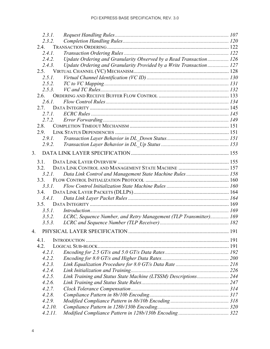
PCI EXPRESS BASE SPECIFICATION, REV. 3.0 2.4. 2.9.1. 2.9.2. 3.3. 3.2.1. 3.3.1. 3.4.1. 2.3.1. 2.3.2. 2.6.1. 2.7.1. 2.7.2. 2.5.1. 2.5.2. 2.5.3. 2.4.1. 2.4.2. 2.4.3. Request Handling Rules...................................................................................... 107 Completion Handling Rules................................................................................ 120 TRANSACTION ORDERING............................................................................................ 122 Transaction Ordering Rules ............................................................................... 122 Update Ordering and Granularity Observed by a Read Transaction................ 126 Update Ordering and Granularity Provided by a Write Transaction ................ 127 2.5. VIRTUAL CHANNEL (VC) MECHANISM........................................................................ 128 Virtual Channel Identification (VC ID) .............................................................. 130 TC to VC Mapping.............................................................................................. 131 VC and TC Rules................................................................................................. 132 2.6. ORDERING AND RECEIVE BUFFER FLOW CONTROL ..................................................... 133 Flow Control Rules............................................................................................. 134 2.7. DATA INTEGRITY ......................................................................................................... 145 ECRC Rules ........................................................................................................ 145 Error Forwarding ............................................................................................... 149 2.8. COMPLETION TIMEOUT MECHANISM ........................................................................... 151 LINK STATUS DEPENDENCIES ...................................................................................... 151 2.9. Transaction Layer Behavior in DL_Down Status............................................... 151 Transaction Layer Behavior in DL_Up Status ................................................... 153 3. DATA LINK LAYER SPECIFICATION.......................................................................... 155 3.1. DATA LINK LAYER OVERVIEW .................................................................................... 155 3.2. DATA LINK CONTROL AND MANAGEMENT STATE MACHINE ...................................... 157 Data Link Control and Management State Machine Rules ................................ 158 FLOW CONTROL INITIALIZATION PROTOCOL ............................................................... 160 Flow Control Initialization State Machine Rules ............................................... 160 3.4. DATA LINK LAYER PACKETS (DLLPS)........................................................................ 164 Data Link Layer Packet Rules ............................................................................ 164 3.5. DATA INTEGRITY ......................................................................................................... 169 Introduction......................................................................................................... 169 LCRC, Sequence Number, and Retry Management (TLP Transmitter).............. 169 LCRC and Sequence Number (TLP Receiver).................................................... 182 4. PHYSICAL LAYER SPECIFICATION ............................................................................ 191 INTRODUCTION ............................................................................................................ 191 LOGICAL SUB-BLOCK................................................................................................... 191 Encoding for 2.5 GT/s and 5.0 GT/s Data Rates ................................................ 192 4.2.1. Encoding for 8.0 GT/s and Higher Data Rates................................................... 200 4.2.2. Link Equalization Procedure for 8.0 GT/s Data Rate ........................................ 218 4.2.3. Link Initialization and Training.......................................................................... 226 4.2.4. Link Training and Status State Machine (LTSSM) Descriptions........................ 244 4.2.5. Link Training and Status State Rules.................................................................. 247 4.2.6. Clock Tolerance Compensation.......................................................................... 314 4.2.7. 4.2.8. Compliance Pattern in 8b/10b Encoding............................................................ 317 4.2.9. Modified Compliance Pattern in 8b/10b Encoding ............................................ 318 4.2.10. Compliance Pattern in 128b/130b Encoding...................................................... 320 4.2.11. Modified Compliance Pattern in 128b/130b Encoding ...................................... 322 3.5.1. 3.5.2. 3.5.3. 4.1. 4.2. 4
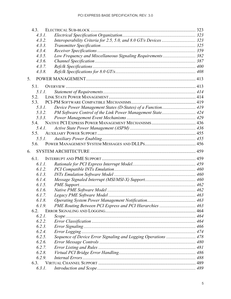
PCI EXPRESS BASE SPECIFICATION, REV. 3.0 4.3. 5.6. 6.1. 6.2. 5.1.1. 5.3.1. 5.3.2. 5.3.3. 5.4.1. 5.5.1. 5.2. 5.3. 4.3.1. 4.3.2. 4.3.3. 4.3.4. 4.3.5. 4.3.6. 4.3.7. 4.3.8. ELECTRICAL SUB-BLOCK ............................................................................................. 323 Electrical Specification Organization................................................................. 323 Interoperability Criteria for 2.5, 5.0, and 8.0 GT/s Devices .............................. 323 Transmitter Specification.................................................................................... 325 Receiver Specifications ....................................................................................... 359 Low Frequency and Miscellaneous Signaling Requirements ............................. 382 Channel Specification ......................................................................................... 387 Refclk Specifications ........................................................................................... 400 Refclk Specifications for 8.0 GT/s....................................................................... 408 5. POWER MANAGEMENT................................................................................................. 413 5.1. OVERVIEW ................................................................................................................... 413 Statement of Requirements.................................................................................. 414 LINK STATE POWER MANAGEMENT............................................................................. 414 PCI-PM SOFTWARE COMPATIBLE MECHANISMS......................................................... 419 Device Power Management States (D-States) of a Function.............................. 419 PM Software Control of the Link Power Management State.............................. 424 Power Management Event Mechanisms ............................................................. 429 5.4. NATIVE PCI EXPRESS POWER MANAGEMENT MECHANISMS....................................... 436 Active State Power Management (ASPM) .......................................................... 436 5.5. AUXILIARY POWER SUPPORT....................................................................................... 455 Auxiliary Power Enabling................................................................................... 455 POWER MANAGEMENT SYSTEM MESSAGES AND DLLPS............................................. 456 6. SYSTEM ARCHITECTURE ............................................................................................. 459 INTERRUPT AND PME SUPPORT................................................................................... 459 Rationale for PCI Express Interrupt Model........................................................ 459 6.1.1. PCI Compatible INTx Emulation........................................................................ 460 6.1.2. 6.1.3. INTx Emulation Software Model ........................................................................ 460 6.1.4. Message Signaled Interrupt (MSI/MSI-X) Support............................................. 460 PME Support....................................................................................................... 462 6.1.5. Native PME Software Model .............................................................................. 462 6.1.6. Legacy PME Software Model ............................................................................. 463 6.1.7. 6.1.8. Operating System Power Management Notification........................................... 463 PME Routing Between PCI Express and PCI Hierarchies ................................ 463 6.1.9. ERROR SIGNALING AND LOGGING................................................................................ 464 Scope................................................................................................................... 464 Error Classification ............................................................................................ 464 Error Signaling ................................................................................................... 466 Error Logging ..................................................................................................... 474 Sequence of Device Error Signaling and Logging Operations .......................... 478 Error Message Controls ..................................................................................... 480 Error Listing and Rules ...................................................................................... 481 Virtual PCI Bridge Error Handling.................................................................... 486 Internal Errors.................................................................................................... 488 6.3. VIRTUAL CHANNEL SUPPORT ...................................................................................... 489 Introduction and Scope....................................................................................... 489 6.2.1. 6.2.2. 6.2.3. 6.2.4. 6.2.5. 6.2.6. 6.2.7. 6.2.8. 6.2.9. 6.3.1. 5
PCI EXPRESS BASE SPECIFICATION, REV. 3.0 6.6. 6.7. 6.6.1. 6.6.2. 6.8.1. 6.3.2. 6.3.3. 6.3.4. 6.7.1. 6.7.2. 6.7.3. 6.7.4. 6.5.1. 6.5.2. 6.5.3. 6.5.4. 6.5.5. 6.5.6. 6.5.7. TC/VC Mapping and Example Usage................................................................. 489 VC Arbitration .................................................................................................... 491 Isochronous Support ........................................................................................... 500 6.4. DEVICE SYNCHRONIZATION......................................................................................... 502 6.5. LOCKED TRANSACTIONS.............................................................................................. 503 Introduction......................................................................................................... 503 Initiation and Propagation of Locked Transactions - Rules............................... 504 Switches and Lock - Rules................................................................................... 505 PCI Express/PCI Bridges and Lock - Rules ....................................................... 506 Root Complex and Lock - Rules.......................................................................... 506 Legacy Endpoints................................................................................................ 506 PCI Express Endpoints ....................................................................................... 506 PCI EXPRESS RESET - RULES....................................................................................... 506 Conventional Reset ............................................................................................. 507 Function-Level Reset (FLR)................................................................................ 510 PCI EXPRESS HOT-PLUG SUPPORT .............................................................................. 514 Elements of Hot-Plug.......................................................................................... 514 Registers Grouped by Hot-Plug Element Association........................................ 520 PCI Express Hot-Plug Events............................................................................. 522 Firmware Support for Hot-Plug ......................................................................... 525 POWER BUDGETING CAPABILITY................................................................................. 526 System Power Budgeting Process Recommendations......................................... 526 SLOT POWER LIMIT CONTROL ..................................................................................... 527 ROOT COMPLEX TOPOLOGY DISCOVERY................................................................. 530 LINK SPEED MANAGEMENT ..................................................................................... 532 ACCESS CONTROL SERVICES (ACS) ........................................................................ 533 6.12.1. ACS Component Capability Requirements ......................................................... 533 6.12.2. Interoperability ................................................................................................... 538 6.12.3. ACS Peer-to-Peer Control Interactions.............................................................. 538 6.12.4. ACS Violation Error Handling ........................................................................... 539 6.12.5. ACS Redirection Impacts on Ordering Rules ..................................................... 540 ALTERNATIVE ROUTING-ID INTERPRETATION (ARI) .............................................. 542 6.13. 6.14. MULTICAST OPERATIONS......................................................................................... 546 6.14.1. Multicast TLP Processing................................................................................... 546 6.14.2. Multicast Ordering.............................................................................................. 549 6.14.3. Multicast Capability Structure Field Updates.................................................... 549 6.14.4. MC Blocked TLP Processing.............................................................................. 550 6.14.5. MC_Overlay Mechanism .................................................................................... 550 ATOMIC OPERATIONS (ATOMICOPS) ....................................................................... 554 6.15.1. AtomicOp Use Models and Benefits ................................................................... 555 6.15.2. AtomicOp Transaction Protocol Summary......................................................... 555 6.15.3. Root Complex Support for AtomicOps................................................................ 557 Switch Support for AtomicOps............................................................................ 559 6.15.4. DYNAMIC POWER ALLOCATION (DPA) CAPABILITY............................................... 559 6.16.1. DPA Capability with Multi-Function Devices.................................................... 560 TLP PROCESSING HINTS (TPH) ............................................................................... 561 6.8. 6.9. 6.10. 6.11. 6.12. 6.16. 6.17. 6.15. 6
PCI EXPRESS BASE SPECIFICATION, REV. 3.0 6.18. 6.19. 7.2.1. 7.2.2. 7.2.3. 7.5.1. 7.5.2. 7.5.3. 7.3.1. 7.3.2. 7.3.3. 7.3.4. 6.17.1. Processing Hints ................................................................................................. 561 Steering Tags ...................................................................................................... 562 6.17.2. 6.17.3. ST Modes of Operation ....................................................................................... 562 6.17.4. TPH Capability ................................................................................................... 563 LATENCY TOLERANCE REPORTING (LTR) MECHANISM .......................................... 564 OPTIMIZED BUFFER FLUSH/FILL (OBFF) MECHANISM............................................ 570 7. SOFTWARE INITIALIZATION AND CONFIGURATION............................................ 575 7.1. CONFIGURATION TOPOLOGY........................................................................................ 575 PCI EXPRESS CONFIGURATION MECHANISMS ............................................................. 576 7.2. PCI 3.0 Compatible Configuration Mechanism ................................................. 577 PCI Express Enhanced Configuration Access Mechanism (ECAM).................. 578 Root Complex Register Block ............................................................................. 582 7.3. CONFIGURATION TRANSACTION RULES....................................................................... 583 Device Number.................................................................................................... 583 Configuration Transaction Addressing............................................................... 584 Configuration Request Routing Rules................................................................. 584 PCI Special Cycles.............................................................................................. 585 7.4. CONFIGURATION REGISTER TYPES .............................................................................. 586 PCI-COMPATIBLE CONFIGURATION REGISTERS........................................................... 587 7.5. Type 0/1 Common Configuration Space............................................................. 588 Type 0 Configuration Space Header................................................................... 595 Type 1 Configuration Space Header................................................................... 597 PCI POWER MANAGEMENT CAPABILITY STRUCTURE.................................................. 601 7.6. 7.7. MSI AND MSI-X CAPABILITY STRUCTURES................................................................ 603 Vector Control for MSI-X Table Entries............................................................. 603 PCI EXPRESS CAPABILITY STRUCTURE........................................................................ 604 PCI Express Capability List Register (Offset 00h)............................................. 605 7.8.1. PCI Express Capabilities Register (Offset 02h) ................................................. 606 7.8.2. Device Capabilities Register (Offset 04h) .......................................................... 608 7.8.3. Device Control Register (Offset 08h) ................................................................. 613 7.8.4. Device Status Register (Offset 0Ah).................................................................... 620 7.8.5. Link Capabilities Register (Offset 0Ch).............................................................. 622 7.8.6. Link Control Register (Offset 10h) ..................................................................... 627 7.8.7. Link Status Register (Offset 12h) ........................................................................ 635 7.8.8. Slot Capabilities Register (Offset 14h) ............................................................... 638 7.8.9. Slot Control Register (Offset 18h) ...................................................................... 640 7.8.10. 7.8.11. Slot Status Register (Offset 1Ah)......................................................................... 644 7.8.12. Root Control Register (Offset 1Ch) .................................................................... 646 7.8.13. Root Capabilities Register (Offset 1Eh) ............................................................. 647 7.8.14. Root Status Register (Offset 20h)........................................................................ 648 7.8.15. Device Capabilities 2 Register (Offset 24h) ....................................................... 649 7.8.16. Device Control 2 Register (Offset 28h) .............................................................. 654 7.8.17. Device Status 2 Register (Offset 2Ah)................................................................. 658 7.8.18. Link Capabilities 2 Register (Offset 2Ch)........................................................... 658 7.8.19. Link Control 2 Register (Offset 30h) .................................................................. 660 7.8.20. Link Status 2 Register (Offset 32h) ..................................................................... 665 7.7.1. 7.8. 7
PCI EXPRESS BASE SPECIFICATION, REV. 3.0 7.9. 7.9.1. 7.9.2. 7.9.3. 7.10. 7.8.21. 7.8.22. 7.8.23. Slot Capabilities 2 Register (Offset 34h) ............................................................ 667 Slot Control 2 Register (Offset 38h) ................................................................... 667 Slot Status 2 Register (Offset 3Ah)...................................................................... 667 PCI EXPRESS EXTENDED CAPABILITIES....................................................................... 667 Extended Capabilities in Configuration Space................................................... 668 Extended Capabilities in the Root Complex Register Block............................... 668 PCI Express Extended Capability Header.......................................................... 669 ADVANCED ERROR REPORTING CAPABILITY........................................................... 670 7.10.1. Advanced Error Reporting Extended Capability Header (Offset 00h)............... 672 7.10.2. Uncorrectable Error Status Register (Offset 04h).............................................. 673 7.10.3. Uncorrectable Error Mask Register (Offset 08h)............................................... 675 7.10.4. Uncorrectable Error Severity Register (Offset 0Ch).......................................... 677 7.10.5. Correctable Error Status Register (Offset 10h).................................................. 679 7.10.6. Correctable Error Mask Register (Offset 14h)................................................... 680 7.10.7. Advanced Error Capabilities and Control Register (Offset 18h) ....................... 681 7.10.8. Header Log Register (Offset 1Ch) ...................................................................... 682 7.10.9. Root Error Command Register (Offset 2Ch) ...................................................... 683 Root Error Status Register (Offset 30h).......................................................... 684 7.10.10. 7.10.11. Error Source Identification Register (Offset 34h) .......................................... 687 TLP Prefix Log Register (Offset 38h) ............................................................. 687 7.10.12. VIRTUAL CHANNEL CAPABILITY ............................................................................. 688 7.11.1. Virtual Channel Extended Capability Header (Offset 00h)................................ 690 7.11.2. Port VC Capability Register 1 (Offset 04h)........................................................ 691 7.11.3. Port VC Capability Register 2 (Offset 08h)........................................................ 692 7.11.4. Port VC Control Register (Offset 0Ch)............................................................... 693 7.11.5. Port VC Status Register (Offset 0Eh).................................................................. 694 7.11.6. VC Resource Capability Register ....................................................................... 695 7.11.7. VC Resource Control Register............................................................................ 697 7.11.8. VC Resource Status Register .............................................................................. 699 7.11.9. VC Arbitration Table .......................................................................................... 700 Port Arbitration Table .................................................................................... 701 7.11.10. DEVICE SERIAL NUMBER CAPABILITY..................................................................... 703 7.12.1. Device Serial Number Extended Capability Header (Offset 00h)...................... 704 7.12.2. Serial Number Register (Offset 04h)................................................................... 705 PCI EXPRESS ROOT COMPLEX LINK DECLARATION CAPABILITY ............................ 705 7.13.1. Root Complex Link Declaration Extended Capability Header (Offset 00h) ...... 707 7.13.2. Element Self Description (Offset 04h) ................................................................ 708 7.13.3. Link Entries......................................................................................................... 709 PCI EXPRESS ROOT COMPLEX INTERNAL LINK CONTROL CAPABILITY................... 713 7.14.1. Root Complex Internal Link Control Extended Capability Header (Offset 00h) 713 7.14.2. Root Complex Link Capabilities Register (Offset 04h)....................................... 714 7.14.3. Root Complex Link Control Register (Offset 08h).............................................. 717 7.14.4. Root Complex Link Status Register (Offset 0Ah)................................................ 719 POWER BUDGETING CAPABILITY............................................................................. 720 7.15.1. Power Budgeting Extended Capability Header (Offset 00h).............................. 721 7.15.2. Data Select Register (Offset 04h) ....................................................................... 721 7.11. 7.12. 7.13. 7.14. 7.15. 8
分享到:
收藏