CiA Draft Standard 408
CANopen
Device profile fluid power technology
proportional valves and hydrostatic transmissions
Version 1.5.2
01 January 2005
© CAN in Automation e. V.
�
DS 408 V 1.5.2 Device profile fluid power technology proportional valves and hydrostatic transmission
CiA
Version
1.0
1.0.1
1.5.1
1.5.2
Changes
Released as work draft
changed values in table physical units from 70h .. 81h to A0h .. B1h
Publication as Draft Standard Proposal
Publication as Draft Standard
- Editorial changes in chapter “references” and “abbreviations”
-
Layout reviewed
History
Date
2002-08-21
2002-11-08
2003-04-30
2005-01-01
General information on licensing and patents
CAN in AUTOMATION (CiA) calls attention to the possibility that some of the elements of this CiA
specification may be subject of patent rights. CiA shall not be responsible for identifying any or all such
patent rights.
Because this specification is licensed free of charge, there is no warranty for this
specification, to the extent permitted by applicable law. Except when otherwise stated in
writing the copyright holder and/or other parties provide this specification “as is” without
warranty of any kind, either expressed or implied, including, but not limited to, the implied
warranties of merchantability and fitness for a particular purpose. The entire risk as to the
correctness and completeness of the specification is with you. Should this specification prove
failures, you assume the cost of all necessary servicing, repair or correction.
© CiA 2008
All rights reserved. Unless otherwise specified, no part of this publication may be reproduced or
utilized in any form or by any means, electronic or mechanical, including photocopying and microfilm,
without permission in writing from CiA at the address below.
CAN in Automation e. V.
Kontumazgarten 3
DE - 90429 Nuremberg, Germany
Tel.: +49-911-928819-0
Fax: +49-911-928819-79
Url: www.can-cia.org
Email: headquarters@can-cia.org
2
© CiA 2008 – All rights reserved
�
DS 408 V 1.5.2 Device profile fluid power technology proportional valves and hydrostatic transmission
CiA
Contents
1 Scope .................................................................................................................................................... 13
1.1 System environment hydrostatic transmissions........................................................................... 13
1.2 System environment valves .......................................................................................................... 13
1.3 System environment hydrostatic pumps ...................................................................................... 14
2 References ........................................................................................................................................... 15
2.1 Normative references .................................................................................................................... 15
3 Abbreviations and definitions .......................................................................................................... 16
3.1 Abreviations.................................................................................................................................... 16
3.2 Definitions ....................................................................................................................................... 16
4 Operating principles........................................................................................................................... 17
4.1 General definitions ......................................................................................................................... 17
4.1.1
Internal resolution.................................................................................................................... 17
4.1.2 Direction of data ...................................................................................................................... 17
4.1.3 Direction of flow....................................................................................................................... 17
4.2 Description of parameters ............................................................................................................. 17
4.2.1 Definition of SI unit and prefix ................................................................................................ 17
4.2.2 Profile-specific units ................................................................................................................ 18
4.3 Device architecture ........................................................................................................................ 19
4.3.1 Mapping of the device architecture to CANopen profile objects.......................................... 19
4.3.2 Relation between statemachines ........................................................................................... 22
5 Emergency messages........................................................................................................................ 23
5.1 Principle .......................................................................................................................................... 23
5.2 Error code meaning ....................................................................................................................... 23
6 Communication objects..................................................................................................................... 25
6.1 Object descriptions ........................................................................................................................ 25
6.1.1 Object 1000h: Device type ...................................................................................................... 25
6.2 Default PDO mapping.................................................................................................................... 25
6.2.1 Transmit PDO mapping .......................................................................................................... 25
6.2.1.1 Mapping parameter of mapping 1................................................................................... 26
6.2.1.2 Mapping parameter of mapping 2................................................................................... 26
6.2.1.3 Mapping parameter of mapping 3................................................................................... 27
6.2.1.4 Mapping parameter of mapping 4................................................................................... 28
6.2.1.5 Mapping parameter of mapping 5................................................................................... 29
6.2.1.6 Mapping parameter of mapping 6................................................................................... 30
6.2.1.7 Mapping parameter of mapping 7................................................................................... 30
6.2.2 Receive PDO mapping ........................................................................................................... 31
6.2.2.1 Mapping parameter of mapping 1................................................................................... 32
6.2.2.2 Mapping parameter of mapping 2................................................................................... 33
6.2.2.3 Mapping parameter of mapping 3................................................................................... 33
6.2.2.4 Mapping parameter of mapping 4................................................................................... 34
© CiA 2008 – All rights reserved
3
�
DS 408 V 1.5.2 Device profile fluid power technology proportional valves and hydrostatic transmission
CiA
6.2.2.5 Mapping parameter of mapping 5................................................................................... 35
6.2.2.6 Mapping parameter of mapping 6................................................................................... 36
6.2.2.7 Mapping parameter of mapping 7................................................................................... 37
6.2.2.8 Mapping parameter of mapping 8................................................................................... 38
7 Object dictionary................................................................................................................................. 39
7.1 Data types and encoding rules ..................................................................................................... 39
7.1.1 Complex data type definitions ................................................................................................ 39
7.1.1.1 Value parameter record Unsigned8 (0080h) .................................................................. 39
7.1.1.2 Value parameter record Unsigned16 (0081h) ................................................................ 39
7.1.1.3 Value parameter record Unsigned32 (0082h) ................................................................ 39
7.1.1.4 Value parameter record Integer8 (0083h)....................................................................... 39
7.1.1.5 Value parameter record Integer16 (0084h)..................................................................... 40
7.1.1.6 Value parameter record Integer32 (0085h)..................................................................... 40
7.1.1.7 Value parameter record Float32 (0086h)........................................................................ 40
7.1.1.8 Value parameter record Float64 (0087h)........................................................................ 40
7.2 Application object definitions......................................................................................................... 40
7.2.1 Overview.................................................................................................................................. 40
7.2.2 Device block ............................................................................................................................ 53
7.2.2.1 Device control................................................................................................................... 53
7.2.2.1.1 Object 6040h: Device control word....................................................................... 53
7.2.2.1.2 Object 6041h: Device status word ........................................................................ 54
7.2.2.1.3 Object 6042h: Device mode ................................................................................... 55
7.2.2.1.4 Object 6043h: Device control mode ..................................................................... 55
7.2.2.1.5 Object 604Eh: Device error code .......................................................................... 56
7.2.2.1.6 Object 604Fh: Device local..................................................................................... 57
7.2.2.2 Device identification ......................................................................................................... 57
7.2.2.2.1 Object 6050h: Device version ................................................................................ 57
7.2.2.2.2 Object 6051h: Device code number...................................................................... 58
7.2.2.2.3 Object 6052h: Device serial number..................................................................... 58
7.2.2.2.4 Object 6053h: Device description ......................................................................... 58
7.2.2.2.5 Object 6054h: Device model description............................................................. 59
7.2.2.2.6 Object 6055h: Device model URL ......................................................................... 59
7.2.2.2.7 Object 6056h: Device parameter set code........................................................... 59
7.2.2.2.8 Object 6057h: Device vendor name...................................................................... 60
7.2.2.2.9 Object 605Fh: Device capability............................................................................ 60
7.2.3 Actual value conditioning........................................................................................................ 61
7.2.3.1 Actual value conditioning for valves................................................................................ 61
7.2.3.1.1 Object 6100h: vlv actual value conditioning max interface number............... 61
7.2.3.1.2 Object 6101h: vlv actual value conditioning interface number ....................... 62
7.2.3.1.3 Object 6102h: vlv actual value conditioning type .............................................. 62
7.2.3.1.4 Object 6103h: vlv actual value conditioning sign .............................................. 63
4
© CiA 2008 – All rights reserved
�
DS 408 V 1.5.2 Device profile fluid power technology proportional valves and hydrostatic transmission
CiA
7.2.3.1.5 Object 6104h: vlv actual value conditioning actual value ................................ 63
7.2.3.1.6 Object 6110h: vlv actual value conditioning actual value 1 ............................. 64
7.2.3.1.7 Object 6111h: vlv actual value conditioning actual value 2 ............................. 66
7.2.3.1.8 Object 6112h: vlv actual value conditioning actual value 3 ............................. 67
7.2.3.1.9 Object 6113h: vlv actual value conditioning actual value 4 ............................. 68
7.2.3.1.10 Object 6114h: vlv actual value conditioning actual value 5 ........................... 70
7.2.3.1.11 Object 6115h: vlv actual value conditioning actual value 6 ........................... 71
7.2.3.1.12 Object 6116h: vlv actual value conditioning actual value 7 ........................... 72
7.2.3.1.13 Object 6117h: vlv actual value conditioning actual value 8 ........................... 73
7.2.3.1.14 Object 6120h: vlv actual value conditioning min pressure ............................ 75
7.2.3.1.15 Object 6121h: vlv actual value conditioning max pressure ........................... 76
7.2.3.1.16 Object 6122h: vlv actual value conditioning area ............................................ 77
7.2.3.1.17 Object 6123h: vlv actual value conditioning pressure offset ........................ 78
7.2.3.1.18 Object 6124h: vlv actual value conditioning min transducer signal ............ 80
7.2.3.1.19 Object 6125h: vlv actual value conditioning max transducer signal............ 81
7.2.3.1.20 Object 6130h: vlv actual value conditioning min reference ........................... 82
7.2.3.1.21 Object 6131h: vlv actual value conditioning max reference .......................... 83
7.2.3.1.22 Object 6132h: vlv actual value conditioning T1 ............................................... 85
7.2.3.1.23 Object 6133h: vlv actual value conditioning min interface ............................ 86
7.2.3.1.24 Object 6134h: vlv actual value conditioning max interface ........................... 87
7.2.3.1.25 Object 6140h: vlv actual value conditioning resolution.................................. 88
7.2.3.1.26 Object 6141h: valve actual value conditioning position offset...................... 90
7.2.3.1.27 Object 6142h: vlv actual value conditioning zero shift................................... 91
7.2.3.1.28 Object 6143h: vlv actual value conditioning bit size ....................................... 92
7.2.3.1.29 Object 6144h: vlv actual value conditioning C ................................................. 93
7.2.3.1.30 Object 6145h: vlv actual value conditioning start stop type.......................... 94
7.2.3.2 Actual value conditioning for drives ................................................................................ 94
7.2.3.2.1 Object 6200h: drv actual value conditioning max interface number.............. 94
7.2.3.2.2 Object 6201h: drv actual value conditioning interface number....................... 95
7.2.3.2.3 Object 6202h: drv actual value conditioning type ............................................. 95
7.2.3.2.4 Object 6203h: drv actual value conditioning sign ............................................. 96
7.2.3.2.5 Object 6204h: drv actual value conditioning actual value................................ 96
7.2.3.2.6 Object 6210h: drv actual value conditioning actual value 1 ............................ 98
7.2.3.2.7 Object 6211h: drv actual value conditioning actual value 2 ............................ 99
7.2.3.2.8 Object 6212h: drv actual value conditioning actual value 3 .......................... 100
7.2.3.2.9 Object 6213h: drv actual value conditioning actual value 4 .......................... 101
7.2.3.2.10 Object 6214h: drv actual value conditioning actual value 5 ........................ 103
7.2.3.2.11 Object 6215h: drv actual value conditioning actual value 6 ........................ 104
7.2.3.2.12 Object 6216h: drv actual value conditioning actual value 7 ........................ 105
7.2.3.2.13 Object 6217h: drv actual value conditioning actual value 8 ........................ 106
7.2.3.2.14 Object 6220h: drv actual value conditioning min pressure ......................... 108
© CiA 2008 – All rights reserved
5
�
DS 408 V 1.5.2 Device profile fluid power technology proportional valves and hydrostatic transmission
CiA
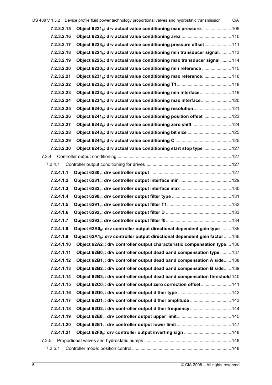
7.2.3.2.15 Object 6221h: drv actual value conditioning max pressure......................... 109
7.2.3.2.16 Object 6222h: drv actual value conditioning area ......................................... 110
7.2.3.2.17 Object 6223h: drv actual value conditioning pressure offset...................... 111
7.2.3.2.18 Object 6224h: drv actual value conditioning min transducer signal.......... 113
7.2.3.2.19 Object 6225h: drv actual value conditioning max transducer signal ......... 114
7.2.3.2.20 Object 6230h: drv actual value conditioning min reference ........................ 115
7.2.3.2.21 Object 6231h: drv actual value conditioning max reference........................ 116
7.2.3.2.22 Object 6232h: drv actual value conditioning T1............................................. 118
7.2.3.2.23 Object 6233h: drv actual value conditioning min interface.......................... 119
7.2.3.2.24 Object 6234h: drv actual value conditioning max interface......................... 120
7.2.3.2.25 Object 6240h: drv actual value conditioning resolution............................... 121
7.2.3.2.26 Object 6241h: drv actual value conditioning position offset ....................... 123
7.2.3.2.27 Object 6242h: drv actual value conditioning zero shift ................................ 124
7.2.3.2.28 Object 6243h: drv actual value conditioning bit size .................................... 125
7.2.3.2.29 Object 6244h: drv actual value conditioning C .............................................. 125
7.2.3.2.30 Object 6245h: drv actual value conditioning start stop type ....................... 127
7.2.4 Controller output conditioning .............................................................................................. 127
7.2.4.1 Controller output conditioning for drives....................................................................... 127
7.2.4.1.1 Object 6280h: drv controller output ................................................................... 127
7.2.4.1.2 Object 6281h: drv controller output interface min........................................... 129
7.2.4.1.3 Object 6282h: drv controller output interface max .......................................... 130
7.2.4.1.4 Object 6290h: drv controller output filter type ................................................. 131
7.2.4.1.5 Object 6291h: drv controller output filter T1..................................................... 132
7.2.4.1.6 Object 6292h: drv controller output filter D ...................................................... 133
7.2.4.1.7 Object 6293h: drv controller output filter f0...................................................... 134
7.2.4.1.8 Object 62A0h: drv controller output directional dependent gain type......... 135
7.2.4.1.9 Object 62A1h: drv controller output directional dependent gain factor ...... 136
7.2.4.1.10 Object 62A2h: drv controller output characteristic compensation type.... 136
7.2.4.1.11 Object 62B0h: drv controller output dead band compensation type ......... 137
7.2.4.1.12 Object 62B1h: drv controller output dead band compensation A side...... 138
7.2.4.1.13 Object 62B2h: drv controller output dead band compensation B side...... 139
7.2.4.1.14 Object 62B3h: drv controller output dead band compensation threshold 140
7.2.4.1.15 Object 62C0h: drv controller output zero correction offset......................... 141
7.2.4.1.16 Object 62D0h: drv controller output dither type ............................................ 142
7.2.4.1.17 Object 62D1h: drv controller output dither amplitude .................................. 143
7.2.4.1.18 Object 62D2h: drv controller output dither frequency .................................. 144
7.2.4.1.19 Object 62E0h: drv controller output upper limit............................................. 145
7.2.4.1.20 Object 62E1h: drv controller output lower limit ............................................. 147
7.2.4.1.21 Object 62F0h: drv controller output inverting sign ....................................... 148
7.2.5 Proportional valves and hydrostatic pumps ........................................................................ 148
7.2.5.1 Controller mode: position control .................................................................................. 148
6
© CiA 2008 – All rights reserved
�
DS 408 V 1.5.2 Device profile fluid power technology proportional valves and hydrostatic transmission
CiA
7.2.5.1.1 Object 6300h: vpoc set point ............................................................................... 148
7.2.5.1.2 Object 6301h: vpoc actual value ......................................................................... 150
7.2.5.1.3 Object 6302h: vpoc interface reference............................................................. 151
7.2.5.1.4 Object 6310h: vpoc demand value generator demand value......................... 151
7.2.5.1.5 Object 6311h: vpoc demand value generator reference value ...................... 153
7.2.5.1.6 Object 6314h: vpoc demand value generator hold set point ......................... 154
7.2.5.1.7 Object 6320h: vpoc demand value generator upper limit............................... 155
7.2.5.1.8 Object 6321h: vpoc demand value generator lower limit ............................... 156
7.2.5.1.9 Object 6322h: vpoc demand value generator scaling factor ......................... 158
7.2.5.1.10 Object 6323h: vpoc demand value generator scaling offset........................ 158
7.2.5.1.11 Object 6324h: vpoc demand value generator zero correction offset ......... 159
7.2.5.1.12 Object 6330h: vpoc demand value generator ramp type.............................. 161
7.2.5.1.13 Object 6331h: vpoc demand value generator ramp acceleration time....... 162
7.2.5.1.14 Object 6332h: vpoc demand value generator ramp acceleration time
positive
163
171
172
169
170
170
167
7.2.6 Object 6333h: vpoc demand value generator ramp acceleration time negative ............... 164
7.2.6.1.1 Object 6334h: vpoc demand value generator ramp deceleration time......... 165
7.2.6.1.2 Object 6335h: vpoc demand value generator ramp deceleration time positive
7.2.6.1.3 Object 6336h: vpoc demand value generator ramp deceleration time
negative 168
7.2.6.1.4 Object 6340h: vpoc demand value generator directional dependent gain type
7.2.6.1.5 Object 6341h: vpoc demand value generator directional dependent gain
factor
7.2.6.1.6 Object 6342h: vpoc demand value generator dead band compensation type
7.2.6.1.7 Object 6343h: vpoc demand value generator dead band compensation A
side
7.2.6.1.8 Object 6344h: vpoc demand value generator dead band compensation B
side
7.2.6.1.9 Object 6345h: vpoc demand value generator dead band compensation
threshold 173
7.2.6.1.10 Object 6346h: vpoc demand value generator characteristic compensation
type
7.2.6.1.11 Object 6350h: vpoc control deviation .............................................................. 175
7.2.6.1.12 Object 6351h: vpoc control monitoring type .................................................. 176
7.2.6.1.13 Object 6352h: vpoc control monitoring delay time........................................ 177
7.2.6.1.14 Object 6353h: vpoc control monitoring threshold......................................... 178
7.2.6.1.15 Object 6354h: vpoc control monitoring upper threshold ............................. 179
7.2.6.1.16 Object 6355h: vpoc control monitoring lower threshold.............................. 181
7.2.6.1.17 Object 6360h: vpoc dither type ......................................................................... 182
7.2.6.1.18 Object 6361h: vpoc dither amplitude ............................................................... 183
7.2.6.1.19 Object 6362h: vpoc dither frequency ............................................................... 184
7.2.6.1.20 Object 6370h: vpoc target window monitoring type...................................... 185
175
© CiA 2008 – All rights reserved
7
�
DS 408 V 1.5.2 Device profile fluid power technology proportional valves and hydrostatic transmission
CiA
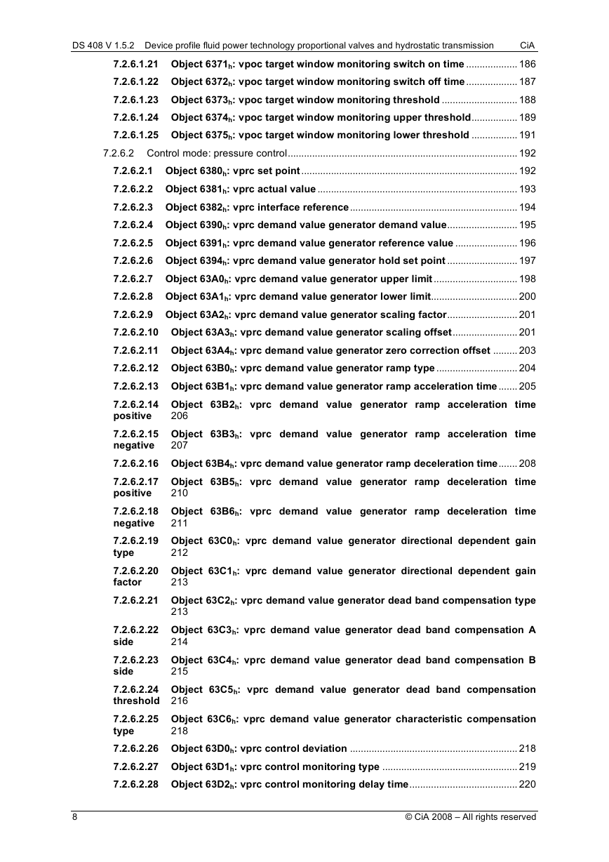
7.2.6.1.21 Object 6371h: vpoc target window monitoring switch on time ................... 186
7.2.6.1.22 Object 6372h: vpoc target window monitoring switch off time................... 187
7.2.6.1.23 Object 6373h: vpoc target window monitoring threshold ............................ 188
7.2.6.1.24 Object 6374h: vpoc target window monitoring upper threshold................. 189
7.2.6.1.25 Object 6375h: vpoc target window monitoring lower threshold ................. 191
7.2.6.2 Control mode: pressure control..................................................................................... 192
7.2.6.2.1 Object 6380h: vprc set point................................................................................ 192
7.2.6.2.2 Object 6381h: vprc actual value .......................................................................... 193
7.2.6.2.3 Object 6382h: vprc interface reference.............................................................. 194
7.2.6.2.4 Object 6390h: vprc demand value generator demand value.......................... 195
7.2.6.2.5 Object 6391h: vprc demand value generator reference value ....................... 196
7.2.6.2.6 Object 6394h: vprc demand value generator hold set point .......................... 197
7.2.6.2.7 Object 63A0h: vprc demand value generator upper limit............................... 198
7.2.6.2.8 Object 63A1h: vprc demand value generator lower limit................................ 200
7.2.6.2.9 Object 63A2h: vprc demand value generator scaling factor.......................... 201
7.2.6.2.10 Object 63A3h: vprc demand value generator scaling offset........................ 201
7.2.6.2.11 Object 63A4h: vprc demand value generator zero correction offset ......... 203
7.2.6.2.12 Object 63B0h: vprc demand value generator ramp type .............................. 204
7.2.6.2.13 Object 63B1h: vprc demand value generator ramp acceleration time....... 205
7.2.6.2.14 Object 63B2h: vprc demand value generator ramp acceleration time
positive
7.2.6.2.15 Object 63B3h: vprc demand value generator ramp acceleration time
negative
7.2.6.2.16 Object 63B4h: vprc demand value generator ramp deceleration time....... 208
7.2.6.2.17 Object 63B5h: vprc demand value generator ramp deceleration time
positive
7.2.6.2.18 Object 63B6h: vprc demand value generator ramp deceleration time
negative
7.2.6.2.19 Object 63C0h: vprc demand value generator directional dependent gain
type
7.2.6.2.20 Object 63C1h: vprc demand value generator directional dependent gain
factor
7.2.6.2.21 Object 63C2h: vprc demand value generator dead band compensation type
7.2.6.2.22 Object 63C3h: vprc demand value generator dead band compensation A
side
7.2.6.2.23 Object 63C4h: vprc demand value generator dead band compensation B
side
7.2.6.2.24 Object 63C5h: vprc demand value generator dead band compensation
threshold 216
7.2.6.2.25 Object 63C6h: vprc demand value generator characteristic compensation
type
7.2.6.2.26 Object 63D0h: vprc control deviation .............................................................. 218
7.2.6.2.27 Object 63D1h: vprc control monitoring type .................................................. 219
7.2.6.2.28 Object 63D2h: vprc control monitoring delay time........................................ 220
213
214
206
207
215
218
210
211
212
213
8
© CiA 2008 – All rights reserved
�
