CiA Draft Standard 410
CANopen
Device profile for inclinometer
Version: 1.2
2 August 2006
CAN in Automation (CiA) e. V.
�
HISTORY
Date
01.09.2000
01.01.2005
24.05.2005
Device profile for inclinometer –
Changes
Released as Version 1.0 as draft standard proposal
Publication as Version 1.1 as Draft Standard
Minor editorial changes
Detailed description of PDO parameters
Corrigendum 1 attached to the Version 1.1
General information on licensing and patents
CAN in AUTOMATION (CiA) calls attention to the possibility that some of the elements of this
CiA specification may be subject of patent rights. CiA shall not be responsible for identifying
any or all such patent rights.
Because this specification is licensed free of charge, there is no warranty for this
specification, to the extent permitted by applicable law. Except when otherwise stated in
writing the copyright holder and/or other parties provide this specification “as is” without
warranty of any kind, either expressed or implied, including, but not limited to, the implied
warranties of merchantability and fitness for a particular purpose. The entire risk as to the
correctness and completeness of the specification is with you. Should this specification prove
failures, you assume the cost of all necessary servicing, repair or correction.
© CiA 2008
All rights reserved. Unless otherwise specified, no part of this publication may be reproduced or
utilized in any form or by any means, electronic or mechanical, including photocopying and microfilm,
without permission in writing from CiA at the address below.
CAN in Automation e. V.
Kontumazgarten 3
DE - 90429 Nuremberg, Germany
Tel.: +49-911-928819-0
Fax: +49-911-928819-79
Url: www.can-cia.org
Email: headquarters@can-cia.org
2
CiA 2008 – All rights reserved
�
Device profile for inclinometer –
CONTENTS
1 Scope ............................................................................................................................... 5
2 Normative references........................................................................................................ 5
3 Abbreviations and definitions ............................................................................................ 5
3.1 Abbreviations........................................................................................................... 5
3.2 Definitions ............................................................................................................... 5
4 Operating principle............................................................................................................ 5
4.1
Introduction ............................................................................................................. 5
4.2 Offset and differential offset..................................................................................... 5
5 Error handling ................................................................................................................... 5
5.1 Principle .................................................................................................................. 5
5.2 Error behavior.......................................................................................................... 5
5.3 Additional error code meanings ............................................................................... 6
6 Predefinitions.................................................................................................................... 7
6.1
Introduction ............................................................................................................. 7
6.2 Pre-defined communication objects ......................................................................... 7
6.2.1 Object 1000h: Device type ........................................................................... 7
6.2.2 Object 1001h: Error register ......................................................................... 7
6.2.3 Object 1029h: Error behavior........................................................................ 7
6.2.4 PDO definition ............................................................................................. 8
7 Object dictionary ............................................................................................................. 13
7.1
Introduction ........................................................................................................... 13
7.2 Application objects ................................................................................................ 13
7.2.1 Object 6000h: Resolution ........................................................................... 13
7.2.2 Object 6010h: Slope long16 ....................................................................... 14
7.2.3 Object 6011h: Slope long16 operating parameter ....................................... 14
7.2.4 Object 6012h: Slope long16 preset value ................................................... 15
7.2.5 Object 6013h: Slope long16 offset.............................................................. 15
7.2.6 Object 6014h: Differential slope long16 offset ............................................ 16
7.2.7 Object 6020h: Slope lateral16 .................................................................... 16
7.2.8 Object 6021h: Slope lateral16 operating parameter .................................... 17
7.2.9 Object 6022h: Slope lateral16 preset value ................................................ 18
7.2.10 Object 6023h: Slope lateral16 offset........................................................... 18
7.2.11 Object 6024h: Differential slope lateral16 offset ......................................... 19
7.2.12 Object 6110h: Slope long32 ....................................................................... 19
7.2.13 Object 6111h: Slope long32 operating parameter ....................................... 20
7.2.14 Object 6112h: Slope long32 preset value ................................................... 21
7.2.15 Object 6113h: Slope long32 offset.............................................................. 21
7.2.16 Object 6114h: Differential slope long32 offset ............................................ 22
7.2.17 Object 6120h: Slope lateral32 .................................................................... 22
7.2.18 Object 6121h: Slope lateral32 operating parameter.................................... 23
7.2.19 Object 6122h: Slope lateral32 preset value ................................................ 24
7.2.20 Object 6123h: Slope lateral32 offset........................................................... 24
7.2.21 Object 6124h: Differential slope lateral32 offset ......................................... 25
7.3 General device profile objects................................................................................ 26
7.3.1 Object 67FFh: Device type ......................................................................... 26
Annex A (informative) ........................................................................................................... 26
CiA 2008 – All rights reserved
3
�
Device profile for inclinometer –
Corrigendum 1...................................................................................................................... 27
4
CiA 2008 – All rights reserved
�
1 Scope
Device profile for inclinometer –
This document represents the CANopen device profile for one- and two-axis inclinometers.
The used communication techniques conform to those described in the CANopen application
layer and communication profile.
2 Normative references
/CiA301/
CiA 301, CANopen application layer and communication profile
3 Abbreviations and definitions
3.1 Abbreviations
CAN
CAN-ID
COB
PDO
SDO
TPDO
Controller area network
CAN identifier
Communication object
Process data object
Service data object
Transmit PDO
3.2 Definitions
The definitions given in /CiA301/ apply to this specification, too.
4 Operating principle
4.1
Introduction
One-axis inclinometers provide only longitudinal slope axis value. Two-axis inclinometers
provide additionally lateral slope axis value. These values are mapped into PDOs by default,
which are transmitted synchronously. The inclinometer device may support optionally sync
producer, time-stamp producer/consumer, emergency producer/consumer functionality, and
additional PDOs. For new designs,
to support heartbeat
functionality.
is highly recommended
it
4.2 Offset and differential offset
The slope value (displayed value) is the sum of the physical measurement (true value),
differential offset and offset.
5 Error handling
5.1 Principle
Emergency messages are triggered by internal errors in the device and they are assigned the
highest possible priority to ensure that they get access to the bus without latency. By default,
the emergency messages shall contain the error field with pre-defined error numbers and
additional information.
5.2 Error behavior
If a serious device failure is detected the module shall enter by default autonomously the pre-
operational state. If object 1029h is implemented, the device can be configured to enter
CiA 2008 – All rights reserved
5
�
alternatively the stopped state or remain in the current state in case of device failure. Device
failures shall include the following communication errors:
Device profile for inclinometer –
• Bus-off conditions of the CAN interface
• Life guarding event with the state ‘occurred’
• Heartbeat event with state ‘occurred’
• Sync error event
Serious device errors are caused by device internal failures, too.
5.3 Additional error code meanings
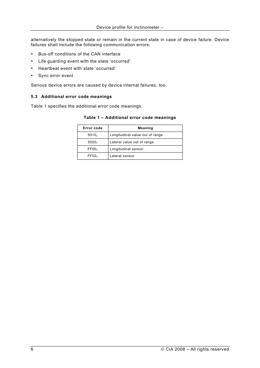
Table 1 specifies the additional error code meanings.
Table 1 – Additional error code meanings
Error code
Meaning
5010h
5020h
FF00h
FF02h
Longitudinal value out of range
Lateral value out of range
Longitudinal sensor
Lateral sensor
6
CiA 2008 – All rights reserved
�
Device profile for inclinometer –
6 Predefinitions
6.1
Introduction
The inclinometer shall support the default TPDO. However, the module may support additional
manufacturer-specific PDOs. Additional TPDOs with
type 255 shall be
transmitted when entering the operational state.
transmission
6.2 Pre-defined communication objects
Modules compliant with this device profile shall come with default values for some
communication objects (1000h to 1FFFh), which are not specified in all details in /CiA301/.
6.2.1
Object 1000h: Device type
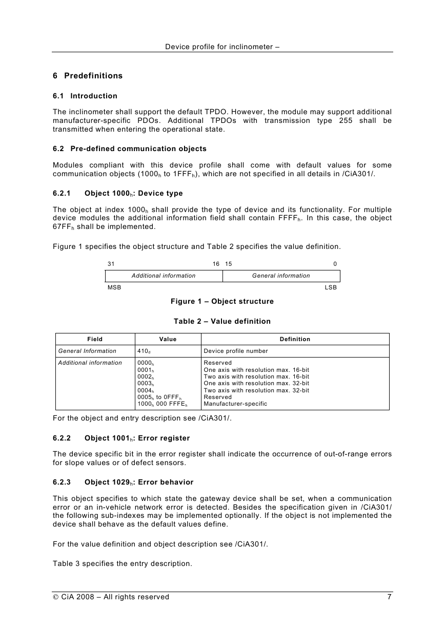
The object at index 1000h shall provide the type of device and its functionality. For multiple
device modules the additional information field shall contain FFFFh. In this case, the object
67FFh shall be implemented.
Figure 1 specifies the object structure and Table 2 specifies the value definition.
31
MSB
Additional information
General information
16 15
Figure 1 – Object structure
Table 2 – Value definition
0
LSB
Field
Value
Definition
General Information
Additional information
410d
0000h
0001h
0002h
0003h
0004h
0005h to 0FFF h
1000h 000 FFFEh
Device profile number
Reserved
One axis with resolution max. 16-bit
Two axis with resolution max. 16-bit
One axis with resolution max. 32-bit
Two axis with resolution max. 32-bit
Reserved
Manufacturer-specific
For the object and entry description see /CiA301/.
6.2.2
Object 1001h: Error register
The device specific bit in the error register shall indicate the occurrence of out-of-range errors
for slope values or of defect sensors.
6.2.3
Object 1029h: Error behavior
This object specifies to which state the gateway device shall be set, when a communication
error or an in-vehicle network error is detected. Besides the specification given in /CiA301/
the following sub-indexes may be implemented optionally. If the object is not implemented the
device shall behave as the default values define.
For the value definition and object description see /CiA301/.
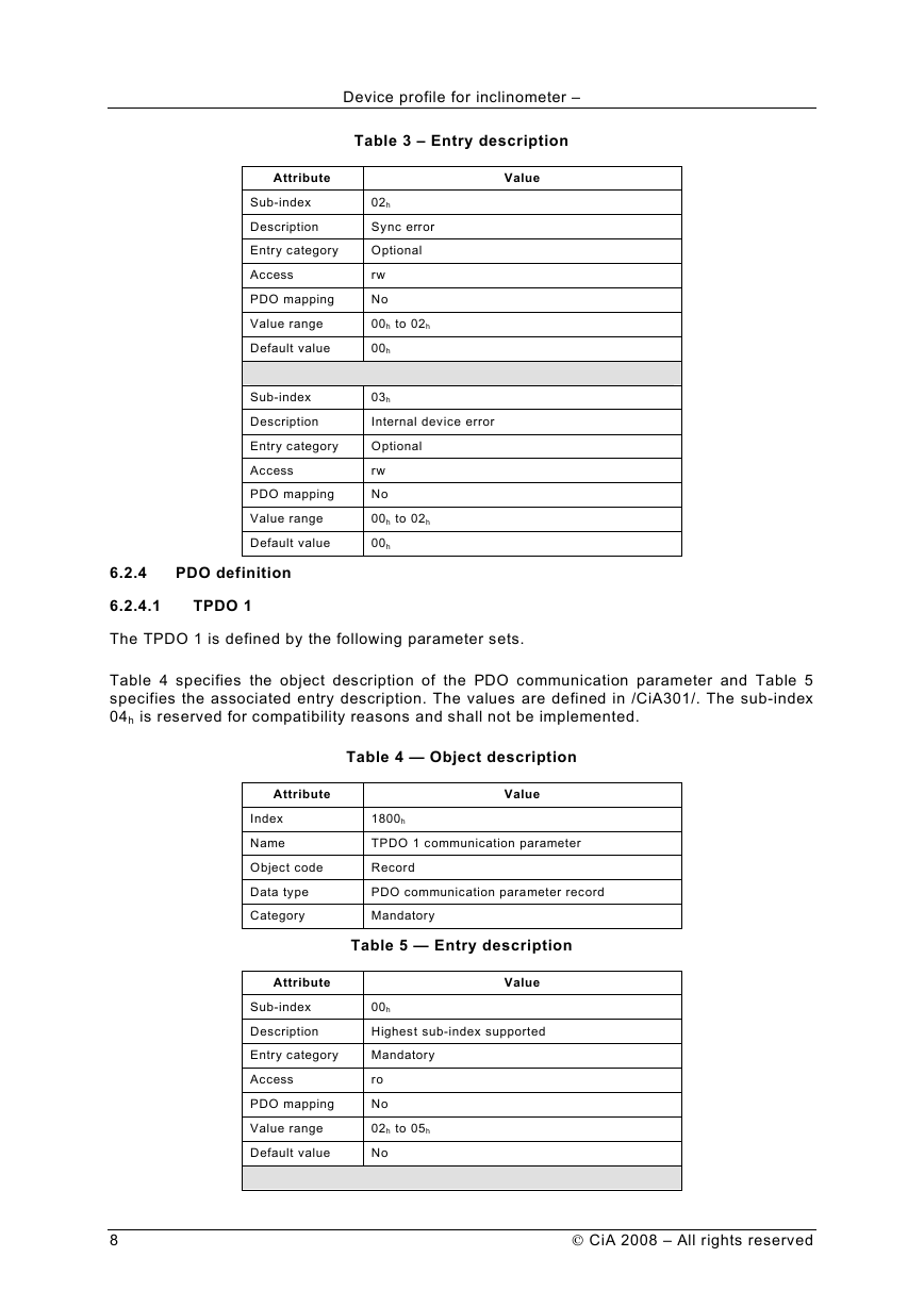
Table 3 specifies the entry description.
CiA 2008 – All rights reserved
7
�
Device profile for inclinometer –
Table 3 – Entry description
Value
02h
Sync error
Optional
rw
No
00h to 02h
00h
03h
Internal device error
Optional
rw
No
00h to 02h
00h
Attribute
Sub-index
Description
Entry category
Access
PDO mapping
Value range
Default value
Sub-index
Description
Entry category
Access
PDO mapping
Value range
Default value
6.2.4
PDO definition
6.2.4.1
TPDO 1
The TPDO 1 is defined by the following parameter sets.
Table 4 specifies the object description of the PDO communication parameter and Table 5
specifies the associated entry description. The values are defined in /CiA301/. The sub-index
04h is reserved for compatibility reasons and shall not be implemented.
Table 4 — Object description
Attribute
Index
Name
Object code
Data type
Category
Value
1800h
TPDO 1 communication parameter
Record
PDO communication parameter record
Mandatory
Table 5 — Entry description
Attribute
Sub-index
Description
Entry category
Access
PDO mapping
Value range
Default value
Value
00h
Highest sub-index supported
Mandatory
ro
No
02h to 05h
No
8
CiA 2008 – All rights reserved
�


