logo资料库

PCI总线规范(英文).pdf

第1页 / 共344页
第2页 / 共344页
第3页 / 共344页
第4页 / 共344页
第5页 / 共344页
第6页 / 共344页
第7页 / 共344页
第8页 / 共344页
资料共344页,剩余部分请下载后查看
Contents
Figures
Tables
Preface
Specification
Incorporation of Engineering Change Notices (ECNs)
Document Conventions
1. Introduction
1.1. Specification Contents
1.2. Motivation
1.3. PCI Local Bus Applications
1.4. PCI Local Bus Overview
1.5. PCI Local Bus Features and Benefits
1.6. Administration
2. Signal Definition
2.1. Signal Type Definition
2.2. Pin Functional Groups
2.2.1. System Pins
2.2.2. Address and Data Pins
2.2.3. Interface Control Pins
2.2.4. Arbitration Pins (Bus Masters Only)
2.2.5. Error Reporting Pins
2.2.6. Interrupt Pins (Optional)
2.2.7. Additional Signals
2.2.8. 64-Bit Bus Extension Pins (Optional)
2.2.9. JTAG/Boundary Scan Pins (Optional)
2.2.10. System Management Bus Interface Pins (Optional)
2.3. Sideband Signals
2.4. Central Resource Functions
3. Bus Operation
3.1. Bus Commands
3.1.1. Command Definition
3.1.2. Command Usage Rules
3.2. PCI Protocol Fundamentals
3.2.1. Basic Transfer Control
3.2.2. Addressing
3.2.2.1. I/O Space Decoding
3.2.2.2. Memory Space Decoding
3.2.2.3. Configuration Space Decoding
3.2.2.3.1. Configuration Commands (Type 0 and Type 1)
3.2.2.3.2. Software Generation of Configuration Transactions
3.2.2.3.3. Software Generation of Special Cycles
3.2.2.3.4. Selection of a Device’s Configuration Space
3.2.2.3.5. System Generation of IDSEL
3.2.3. Byte Lane and Byte Enable Usage
3.2.4. Bus Driving and Turnaround
3.2.5. Transaction Ordering and Posting
3.2.5.1. Transaction Ordering and Posting for Simple
3.2.5.2. Transaction Ordering and Posting for Bridges
3.2.6. Combining, Merging, and Collapsing
3.3. Bus Transactions
3.3.1. Read Transaction
3.3.2. Write Transaction
3.3.3. Transaction Termination
3.3.3.1. Master Initiated Termination
3.3.3.2. Target Initiated Termination
3.3.3.2.1. Target Termination Signaling Rules
3.3.3.2.2. Requirements on a Master Because of Target
3.3.3.3. Delayed Transactions
3.3.3.3.1. Basic Operation of a Delayed Transaction
3.3.3.3.2. Information Required to Complete a Delayed
3.3.3.3.3. Discarding a Delayed Transaction
3.3.3.3.4. Memory Writes and Delayed Transactions
3.3.3.3.5. Supporting Multiple Delayed Transactions
3.4. Arbitration
3.4.1. Arbitration Signaling Protocol
3.4.2. Fast Back-to-Back Transactions
3.4.3. Arbitration Parking
3.5. Latency
3.5.1. Target Latency
3.5.1.1. Target Initial Latency
3.5.1.2. Target Subsequent Latency
3.5.2. Master Data Latency
3.5.3. Memory Write Maximum Completion Time Limit
3.5.4. Arbitration Latency
3.5.4.1. Bandwidth and Latency Considerations
3.5.4.2. Determining Arbitration Latency
3.5.4.3. Determining Buffer Requirements
3.6. Other Bus Operations
3.6.1. Device Selection
3.6.2. Special Cycle
3.6.3. IDSEL Stepping
3.6.4. Interrupt Acknowledge
3.7. Error Functions
3.7.1. Parity Generation
3.7.2. Parity Checking
3.7.3. Address Parity Errors
3.7.4. Error Reporting
3.7.4.1. Data Parity Error Signaling on PERR#
3.7.4.2. Other Error Signaling on SERR#
3.7.4.3. Master Data Parity Error Status Bit
3.7.4.4. Detected Parity Error Status Bit
3.7.5. Delayed Transactions and Data Parity Errors
3.7.6. Error Recovery
3.8. 64-Bit Bus Extension
3.8.1. Determining Bus Width During System Initialization
3.9. 64-bit Addressing
3.10. Special Design Considerations
4. Electrical Specification
4.1. Overview
4.1.1. Transition Road Map
4.1.2. Dynamic vs. Static Drive Specification
4.2. Component Specification
4.2.1. 5V Signaling Environment
4.2.1.1. DC Specifications
4.2.1.2. AC Specifications
4.2.1.3. Maximum AC Ratings and Device Protection
4.2.2. 3.3V Signaling Environment
4.2.2.1. DC Specifications
4.2.2.2. AC Specifications
4.2.2.3. Maximum AC Ratings and Device Protection
4.2.3. Timing Specification
4.2.3.1. Clock Specification
4.2.3.2. Timing Parameters
4.2.3.3. Measurement and Test Conditions
4.2.4. Indeterminate Inputs and Metastability
4.2.5. Vendor Provided Specification
4.2.6. Pinout Recommendation
4.3. System Board Specification
4.3.1. Clock Skew
4.3.2. Reset
4.3.3. Pull-ups
4.3.4. Power
4.3.4.1. Power Requirements
4.3.4.2. Sequencing
4.3.4.3. Decoupling
4.3.5. System Timing Budget
4.3.6. Physical Requirements
4.3.6.1. Routing and Layout Recommendations for Four-Layer
4.3.6.2. System Board Impedance
4.3.7. Connector Pin Assignments
4.4. Add-in Card Specification
4.4.1. Add-in Card Pin Assignment
4.4.2. Power Requirements
4.4.2.1. Decoupling
4.4.2.2. Power Consumption
4.4.3. Physical Requirements
4.4.3.1. Trace Length Limits
4.4.3.2. Routing Recommendations for Four-Layer Add- in
4.4.3.3. Impedance
4.4.3.4. Signal Loading
5. Mechanical Specification
5.1. Overview
5.2. Add-in Card Physical Dimensions and Tolerances
5.3. Connector Physical Description
5.4. Connector Physical Requirements
5.5. Connector Performance Specification
5.6. System Board Implementation
6. Configuration Space
6.1. Configuration Space Organization
6.2. Configuration Space Functions
6.2.1. Device Identification
6.2.2. Device Control
6.2.3. Device Status
6.2.4. Miscellaneous Registers
6.2.5. Base Addresses
6.2.5.1. Address Maps
6.2.5.2. Expansion ROM Base Address Register
6.3. PCI Expansion ROMs
6.4. Vital Product Data
6.5. Device Drivers
6.6. System Reset
6.7. Capabilities List
6.8. Message Signaled Interrupts
6.8.1. MSI Capability Structure
6.8.1.1. Capability ID for MSI
6.8.1.2. Next Pointer for MSI
6.8.1.3. Message Control for MSI
6.8.1.4. Message Address for MSI
6.8.1.5. Message Upper Address for MSI (Optional)
6.8.1.6. Message Data for MSI
6.8.1.7. Mask Bits for MSI (Optional)
6.8.1.8. Pending Bits for MSI (Optional)
6.8.2. MSI-X Capability and Table Structures
6.8.2.1. Capability ID for MSI-X
6.8.2.2. Next Pointer for MSI-X
6.8.2.3. Message Control for MSI-X
6.8.2.4. Table Offset/Table BIR for MSI-X
6.8.2.5. PBA Offset/PBA BIR for MSI-X
6.8.2.6. Message Address for MSI-X Table Entries
6.8.2.7. Message Upper Address for MSI-X Table Entries
6.8.2.8. Message Data for MSI-X Table Entries
6.8.2.9. Vector Control for MSI-X Table Entries
6.8.2.10. Pending Bits for MSI-X PBA Entries
6.8.3. MSI and MSI-X Operation
6.8.3.1. MSI Configuration
6.8.3.2. MSI-X Configuration
6.8.3.3. Enabling Operation
6.8.3.4. Sending Messages
6.8.3.5. Per-vector Masking and Function Masking
6.8.3.6. Hardware/Software Synchronization
6.8.3.7. Message Transaction Termination
6.8.3.8. Message Transaction Reception and Ordering
7. 66 MHz PCI Specification
7.1. Introduction
7.2. Scope
7.3. Device Implementation Considerations
7.3.1. Configuration Space
7.4. Agent Architecture
7.5. Protocol
7.5.1. 66MHZ_ENABLE (M66EN) Pin Definition
7.5.2. Latency
7.6. Electrical Specification
7.6.1. Overview
7.6.2. Transition Roadmap to 66 MHz PCI
7.6.3. Signaling Environment
7.6.3.1. DC Specifications
7.6.3.2. AC Specifications
7.6.3.3. Maximum AC Ratings and Device Protection
7.6.4. Timing Specification
7.6.4.1. Clock Specification
7.6.4.2. Timing Parameters
7.6.4.3. Measurement and Test Conditions
7.6.5. Vendor Provided Specification
7.6.6. Recommendations
7.6.6.1. Pinout Recommendations
7.6.6.2. Clocking Recommendations
7.7. System Board Specification
7.7.1. Clock Uncertainty
7.7.2. Reset
7.7.3. Pullups
7.7.4. Power
7.7.4.1. Power Requirements
7.7.4.2. Sequencing
7.7.4.3. Decoupling
7.7.5. System Timing Budget
7.7.6. Physical Requirements
7.7.6.1. Routing and Layout Recommendations for Four-Layer
7.7.6.2. System Board Impedance
7.7.7. Connector Pin Assignments
7.8. Add-in Card Specifications
8. System Support for SMBus
8.1. SMBus System Requirements
8.1.1. Power
8.1.2. Physical and Logical SMBus
8.1.3. Bus Connectivity
8.1.4. Master and Slave Support
8.1.5. Addressing and Configuration
8.1.6. Electrical
8.1.7. SMBus Behavior on PCI Reset
8.2. Add-in Card SMBus Requirements
8.2.1. Connection
8.2.2. Master and Slave Support
8.2.3. Addressing and Configuration
8.2.4. Power
8.2.5. Electrical
A. Special Cycle Messages
A.1. Message Encodings
A.2. Use of Specific Encodings
B. State Machines
B.1. Target LOCK Machine
B.2. Master Sequencer Machine
B.3. Master LOCK Machine
C. Operating Rules
C.1. When Signals are Stable
C.2. Master Signals
C.3. Target Signals
C.4. Data Phases
C.5. Arbitration
C.6. Latency
C.7. Device Selection
C.8. Parity
D. Class Codes
D.1. Base Class 00h
D.2. Base Class 01h
D.3. Base Class 02h
D.4. Base Class 03h
D.5. Base Class 04h
D.6. Base Class 05h
D.7. Base Class 06h
D.8. Base Class 07h
D.9. Base Class 08h
D.10. Base Class 09h
D.11. Base Class 0Ah
D.12. Base Class 0Bh
D.13. Base Class 0Ch
D.14. Base Class 0Dh
D.15. Base Class 0Eh
D.16. Base Class 0Fh
D.17. Base Class 10h
D.18. Base Class 11h
E. System Transaction Ordering
E.1. Producer - Consumer Ordering Model
E.2. Summary of PCI Ordering Requirements
E.3. Ordering of Requests
E.4. Ordering of Delayed Transactions
E.5. Delayed Transactions and LOCK#
E.6. Error Conditions
F. Exclusive Accesses
F.1. Exclusive Accesses on PCI
F.2. Starting an Exclusive Access
F.3. Continuing an Exclusive Access
F.4. Accessing a Locked Agent
F.5. Completing an Exclusive Access
F.6. Complete Bus Lock
G. I/O Space Address Decoding for Legacy Devices
H. Capability IDs
I. Vital Product Data
I.1. VPD Format
I.2. Compatibility
I.3. VPD Definitions
I.3.1. VPD Large and Small Resource Data Tags
I.3.1.1. Read-Only Fields
I.3.1.2. Read/Write Fields
I.3.2. VPD Example
Glossary
PCI Local Bus Specification Revision 3.0 February 3, 2004
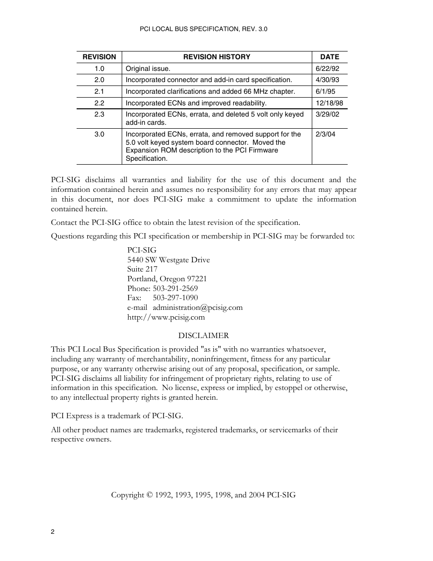
PCI LOCAL BUS SPECIFICATION, REV. 3.0 REVISION REVISION HISTORY 1.0 2.0 2.1 2.2 2.3 3.0 Original issue. Incorporated connector and add-in card specification. Incorporated clarifications and added 66 MHz chapter. Incorporated ECNs and improved readability. Incorporated ECNs, errata, and deleted 5 volt only keyed add-in cards. Incorporated ECNs, errata, and removed support for the 5.0 volt keyed system board connector. Moved the Expansion ROM description to the PCI Firmware Specification. DATE 6/22/92 4/30/93 6/1/95 12/18/98 3/29/02 2/3/04 PCI-SIG disclaims all warranties and liability for the use of this document and the information contained herein and assumes no responsibility for any errors that may appear in this document, nor does PCI-SIG make a commitment to update the information contained herein. Contact the PCI-SIG office to obtain the latest revision of the specification. Questions regarding this PCI specification or membership in PCI-SIG may be forwarded to: PCI-SIG 5440 SW Westgate Drive Suite 217 Portland, Oregon 97221 Phone: 503-291-2569 Fax: 503-297-1090 e-mail administration@pcisig.com http://www.pcisig.com DISCLAIMER This PCI Local Bus Specification is provided "as is" with no warranties whatsoever, including any warranty of merchantability, noninfringement, fitness for any particular purpose, or any warranty otherwise arising out of any proposal, specification, or sample. PCI-SIG disclaims all liability for infringement of proprietary rights, relating to use of information in this specification. No license, express or implied, by estoppel or otherwise, to any intellectual property rights is granted herein. PCI Express is a trademark of PCI-SIG. All other product names are trademarks, registered trademarks, or servicemarks of their respective owners. Copyright © 1992, 1993, 1995, 1998, and 2004 PCI-SIG 2
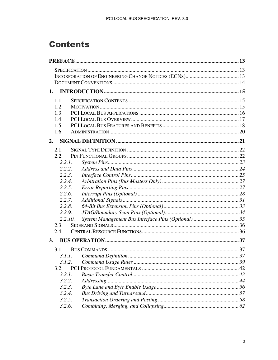
PCI LOCAL BUS SPECIFICATION, REV. 3.0 Contents 1. 2.1. 2.2. PREFACE........................................................................................................................ 13 SPECIFICATION ............................................................................................................... 13 INCORPORATION OF ENGINEERING CHANGE NOTICES (ECNS)....................................... 13 DOCUMENT CONVENTIONS ............................................................................................ 14 INTRODUCTION................................................................................................... 15 1.1. SPECIFICATION CONTENTS ................................................................................. 15 1.2. MOTIVATION...................................................................................................... 15 PCI LOCAL BUS APPLICATIONS ......................................................................... 16 1.3. PCI LOCAL BUS OVERVIEW............................................................................... 17 1.4. 1.5. PCI LOCAL BUS FEATURES AND BENEFITS ........................................................ 18 1.6. ADMINISTRATION............................................................................................... 20 2. SIGNAL DEFINITION .......................................................................................... 21 SIGNAL TYPE DEFINITION .................................................................................. 22 PIN FUNCTIONAL GROUPS.................................................................................. 22 System Pins................................................................................................ 23 Address and Data Pins.............................................................................. 24 Interface Control Pins............................................................................... 25 Arbitration Pins (Bus Masters Only) ........................................................ 27 Error Reporting Pins................................................................................. 27 Interrupt Pins (Optional) .......................................................................... 28 Additional Signals ..................................................................................... 31 64-Bit Bus Extension Pins (Optional) ....................................................... 33 JTAG/Boundary Scan Pins (Optional)...................................................... 34 System Management Bus Interface Pins (Optional) ................................. 35 SIDEBAND SIGNALS............................................................................................ 36 2.3. 2.4. CENTRAL RESOURCE FUNCTIONS....................................................................... 36 3. BUS OPERATION.................................................................................................. 37 3.1. BUS COMMANDS ................................................................................................ 37 Command Definition ................................................................................. 37 Command Usage Rules ............................................................................. 39 PCI PROTOCOL FUNDAMENTALS ....................................................................... 42 Basic Transfer Control.............................................................................. 43 Addressing................................................................................................. 44 Byte Lane and Byte Enable Usage ............................................................ 56 Bus Driving and Turnaround .................................................................... 57 Transaction Ordering and Posting ........................................................... 58 Combining, Merging, and Collapsing....................................................... 62 2.2.1. 2.2.2. 2.2.3. 2.2.4. 2.2.5. 2.2.6. 2.2.7. 2.2.8. 2.2.9. 2.2.10. 3.2. 3.1.1. 3.1.2. 3.2.1. 3.2.2. 3.2.3. 3.2.4. 3.2.5. 3.2.6. 3
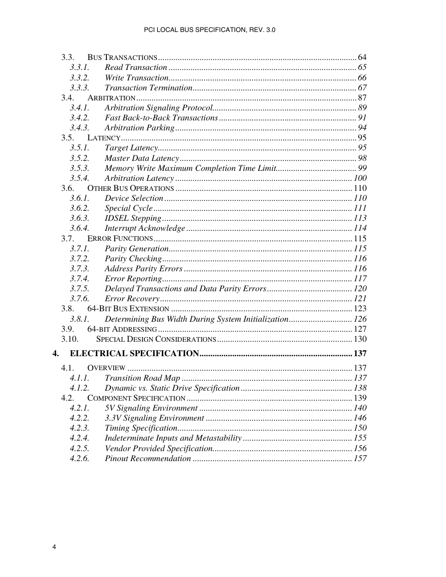
PCI LOCAL BUS SPECIFICATION, REV. 3.0 3.5. 3.4.1. 3.4.2. 3.4.3. 3.3. BUS TRANSACTIONS........................................................................................... 64 3.3.1. Read Transaction ...................................................................................... 65 3.3.2. Write Transaction...................................................................................... 66 3.3.3. Transaction Termination........................................................................... 67 3.4. ARBITRATION..................................................................................................... 87 Arbitration Signaling Protocol.................................................................. 89 Fast Back-to-Back Transactions ............................................................... 91 Arbitration Parking................................................................................... 94 LATENCY............................................................................................................ 95 3.5.1. Target Latency........................................................................................... 95 3.5.2. Master Data Latency................................................................................. 98 3.5.3. Memory Write Maximum Completion Time Limit..................................... 99 Arbitration Latency ................................................................................. 100 3.5.4. 3.6. OTHER BUS OPERATIONS ................................................................................. 110 Device Selection ...................................................................................... 110 Special Cycle ........................................................................................... 111 IDSEL Stepping....................................................................................... 113 Interrupt Acknowledge ............................................................................ 114 ERROR FUNCTIONS........................................................................................... 115 Parity Generation.................................................................................... 115 Parity Checking....................................................................................... 116 Address Parity Errors ............................................................................. 116 Error Reporting....................................................................................... 117 Delayed Transactions and Data Parity Errors....................................... 120 Error Recovery........................................................................................ 121 64-BIT BUS EXTENSION ................................................................................... 123 Determining Bus Width During System Initialization............................. 126 64-BIT ADDRESSING ......................................................................................... 127 SPECIAL DESIGN CONSIDERATIONS.............................................................. 130 4. ELECTRICAL SPECIFICATION...................................................................... 137 4.1. OVERVIEW ....................................................................................................... 137 Transition Road Map .............................................................................. 137 Dynamic vs. Static Drive Specification ................................................... 138 4.2. COMPONENT SPECIFICATION............................................................................ 139 5V Signaling Environment ...................................................................... 140 3.3V Signaling Environment ................................................................... 146 Timing Specification................................................................................ 150 Indeterminate Inputs and Metastability .................................................. 155 Vendor Provided Specification................................................................ 156 Pinout Recommendation ......................................................................... 157 4.2.1. 4.2.2. 4.2.3. 4.2.4. 4.2.5. 4.2.6. 4.1.1. 4.1.2. 3.6.1. 3.6.2. 3.6.3. 3.6.4. 3.7.1. 3.7.2. 3.7.3. 3.7.4. 3.7.5. 3.7.6. 3.8.1. 3.7. 3.8. 3.9. 3.10. 4
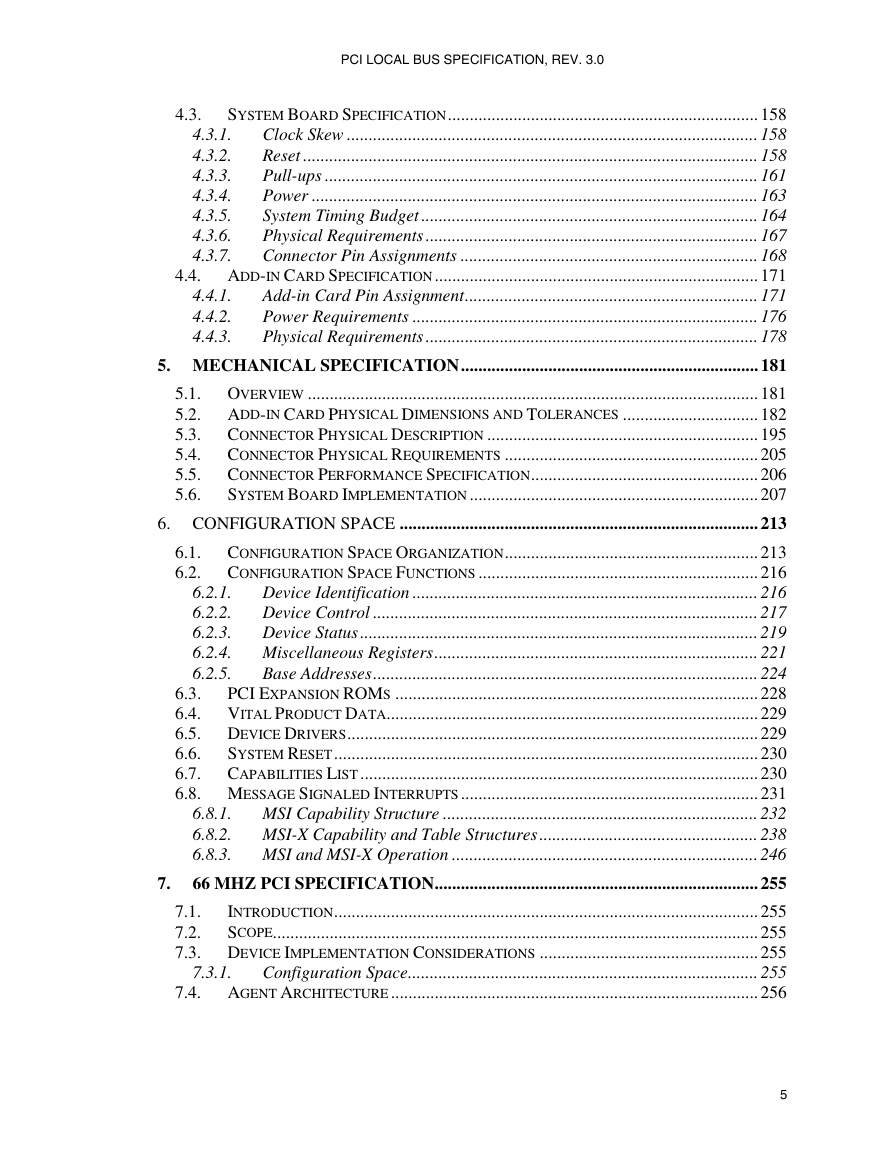
PCI LOCAL BUS SPECIFICATION, REV. 3.0 4.3. 4.4.1. 4.4.2. 4.4.3. 4.3.1. 4.3.2. 4.3.3. 4.3.4. 4.3.5. 4.3.6. 4.3.7. SYSTEM BOARD SPECIFICATION....................................................................... 158 Clock Skew .............................................................................................. 158 Reset ........................................................................................................ 158 Pull-ups ................................................................................................... 161 Power ...................................................................................................... 163 System Timing Budget ............................................................................. 164 Physical Requirements ............................................................................ 167 Connector Pin Assignments .................................................................... 168 4.4. ADD-IN CARD SPECIFICATION.......................................................................... 171 Add-in Card Pin Assignment................................................................... 171 Power Requirements ............................................................................... 176 Physical Requirements ............................................................................ 178 5. MECHANICAL SPECIFICATION.................................................................... 181 5.1. OVERVIEW ....................................................................................................... 181 5.2. ADD-IN CARD PHYSICAL DIMENSIONS AND TOLERANCES ............................... 182 5.3. CONNECTOR PHYSICAL DESCRIPTION .............................................................. 195 5.4. CONNECTOR PHYSICAL REQUIREMENTS .......................................................... 205 5.5. CONNECTOR PERFORMANCE SPECIFICATION.................................................... 206 SYSTEM BOARD IMPLEMENTATION .................................................................. 207 5.6. 6. CONFIGURATION SPACE .................................................................................. 213 6.1. CONFIGURATION SPACE ORGANIZATION.......................................................... 213 6.2. CONFIGURATION SPACE FUNCTIONS ................................................................ 216 6.2.1. Device Identification ............................................................................... 216 6.2.2. Device Control ........................................................................................ 217 6.2.3. Device Status ........................................................................................... 219 6.2.4. Miscellaneous Registers.......................................................................... 221 Base Addresses........................................................................................ 224 6.2.5. PCI EXPANSION ROMS ................................................................................... 228 6.3. 6.4. VITAL PRODUCT DATA..................................................................................... 229 6.5. DEVICE DRIVERS.............................................................................................. 229 6.6. SYSTEM RESET................................................................................................. 230 6.7. CAPABILITIES LIST ........................................................................................... 230 6.8. MESSAGE SIGNALED INTERRUPTS .................................................................... 231 6.8.1. MSI Capability Structure ........................................................................ 232 6.8.2. MSI-X Capability and Table Structures .................................................. 238 6.8.3. MSI and MSI-X Operation ...................................................................... 246 66 MHZ PCI SPECIFICATION.......................................................................... 255 INTRODUCTION................................................................................................. 255 7.1. SCOPE............................................................................................................... 255 7.2. 7.3. DEVICE IMPLEMENTATION CONSIDERATIONS .................................................. 255 Configuration Space................................................................................ 255 7.4. AGENT ARCHITECTURE .................................................................................... 256 7. 7.3.1. 5
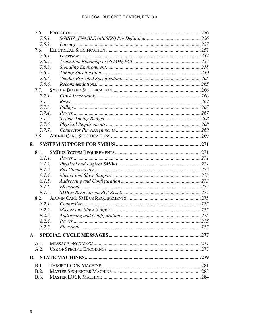
PCI LOCAL BUS SPECIFICATION, REV. 3.0 7.5. 7.6. 7.7. 7.5.1. 7.5.2. 7.6.1. 7.6.2. 7.6.3. 7.6.4. 7.6.5. 7.6.6. 8.1. 7.7.1. 7.7.2. 7.7.3. 7.7.4. 7.7.5. 7.7.6. 7.7.7. PROTOCOL........................................................................................................ 256 66MHZ_ENABLE (M66EN) Pin Definition............................................ 256 Latency .................................................................................................... 257 ELECTRICAL SPECIFICATION ............................................................................ 257 Overview.................................................................................................. 257 Transition Roadmap to 66 MHz PCI ...................................................... 257 Signaling Environment............................................................................ 258 Timing Specification................................................................................ 259 Vendor Provided Specification................................................................ 265 Recommendations.................................................................................... 265 SYSTEM BOARD SPECIFICATION....................................................................... 266 Clock Uncertainty ................................................................................... 266 Reset ........................................................................................................ 267 Pullups..................................................................................................... 267 Power ...................................................................................................... 267 System Timing Budget ............................................................................. 268 Physical Requirements ............................................................................ 268 Connector Pin Assignments .................................................................... 269 7.8. ADD-IN CARD SPECIFICATIONS ........................................................................ 269 8. SYSTEM SUPPORT FOR SMBUS .................................................................... 271 SMBUS SYSTEM REQUIREMENTS..................................................................... 271 Power ...................................................................................................... 271 8.1.1. Physical and Logical SMBus................................................................... 271 8.1.2. 8.1.3. Bus Connectivity...................................................................................... 272 8.1.4. Master and Slave Support ....................................................................... 273 Addressing and Configuration ................................................................ 273 8.1.5. Electrical ................................................................................................. 274 8.1.6. 8.1.7. SMBus Behavior on PCI Reset................................................................ 274 8.2. ADD-IN CARD SMBUS REQUIREMENTS ........................................................... 275 8.2.1. Connection .............................................................................................. 275 8.2.2. Master and Slave Support ....................................................................... 275 Addressing and Configuration ................................................................ 275 8.2.3. 8.2.4. Power ...................................................................................................... 275 Electrical ................................................................................................. 275 8.2.5. A. SPECIAL CYCLE MESSAGES.......................................................................... 277 A.1. MESSAGE ENCODINGS...................................................................................... 277 A.2. USE OF SPECIFIC ENCODINGS ........................................................................... 277 B. STATE MACHINES............................................................................................. 279 B.1. TARGET LOCK MACHINE................................................................................ 281 B.2. MASTER SEQUENCER MACHINE ....................................................................... 283 B.3. MASTER LOCK MACHINE ............................................................................... 284 6
PCI LOCAL BUS SPECIFICATION, REV. 3.0 C. OPERATING RULES .......................................................................................... 289 C.1. WHEN SIGNALS ARE STABLE............................................................................ 289 C.2. MASTER SIGNALS............................................................................................. 290 C.3. TARGET SIGNALS ............................................................................................. 291 C.4. DATA PHASES .................................................................................................. 292 C.5. ARBITRATION................................................................................................... 292 C.6. LATENCY.......................................................................................................... 293 C.7. DEVICE SELECTION .......................................................................................... 293 C.8. PARITY............................................................................................................. 294 D. CLASS CODES ..................................................................................................... 295 D.1. BASE CLASS 00H.............................................................................................. 296 D.2. BASE CLASS 01H.............................................................................................. 296 D.3. BASE CLASS 02H.............................................................................................. 297 D.4. BASE CLASS 03H.............................................................................................. 297 D.5. BASE CLASS 04H.............................................................................................. 298 D.6. BASE CLASS 05H.............................................................................................. 298 D.7. BASE CLASS 06H.............................................................................................. 299 D.8. BASE CLASS 07H.............................................................................................. 300 D.9. BASE CLASS 08H.............................................................................................. 301 BASE CLASS 09H.......................................................................................... 301 D.10. D.11. BASE CLASS 0AH ......................................................................................... 302 BASE CLASS 0BH ......................................................................................... 302 D.12. BASE CLASS 0CH ......................................................................................... 303 D.13. BASE CLASS 0DH ......................................................................................... 304 D.14. D.15. BASE CLASS 0EH ......................................................................................... 304 BASE CLASS 0FH.......................................................................................... 304 D.16. BASE CLASS 10H.......................................................................................... 305 D.17. BASE CLASS 11H.......................................................................................... 305 D.18. E. SYSTEM TRANSACTION ORDERING........................................................... 307 E.1. PRODUCER - CONSUMER ORDERING MODEL.................................................... 308 E.2. SUMMARY OF PCI ORDERING REQUIREMENTS ................................................ 310 E.3. ORDERING OF REQUESTS.................................................................................. 311 E.4. ORDERING OF DELAYED TRANSACTIONS ......................................................... 312 E.5. DELAYED TRANSACTIONS AND LOCK#........................................................... 317 E.6. ERROR CONDITIONS ......................................................................................... 318 F. EXCLUSIVE ACCESSES.................................................................................... 319 F.1. EXCLUSIVE ACCESSES ON PCI ......................................................................... 320 F.2. STARTING AN EXCLUSIVE ACCESS ................................................................... 321 F.3. CONTINUING AN EXCLUSIVE ACCESS............................................................... 323 F.4. ACCESSING A LOCKED AGENT ......................................................................... 324 F.5. COMPLETING AN EXCLUSIVE ACCESS .............................................................. 325 F.6. COMPLETE BUS LOCK ...................................................................................... 325 I/O SPACE ADDRESS DECODING FOR LEGACY DEVICES................ 327 G. 7
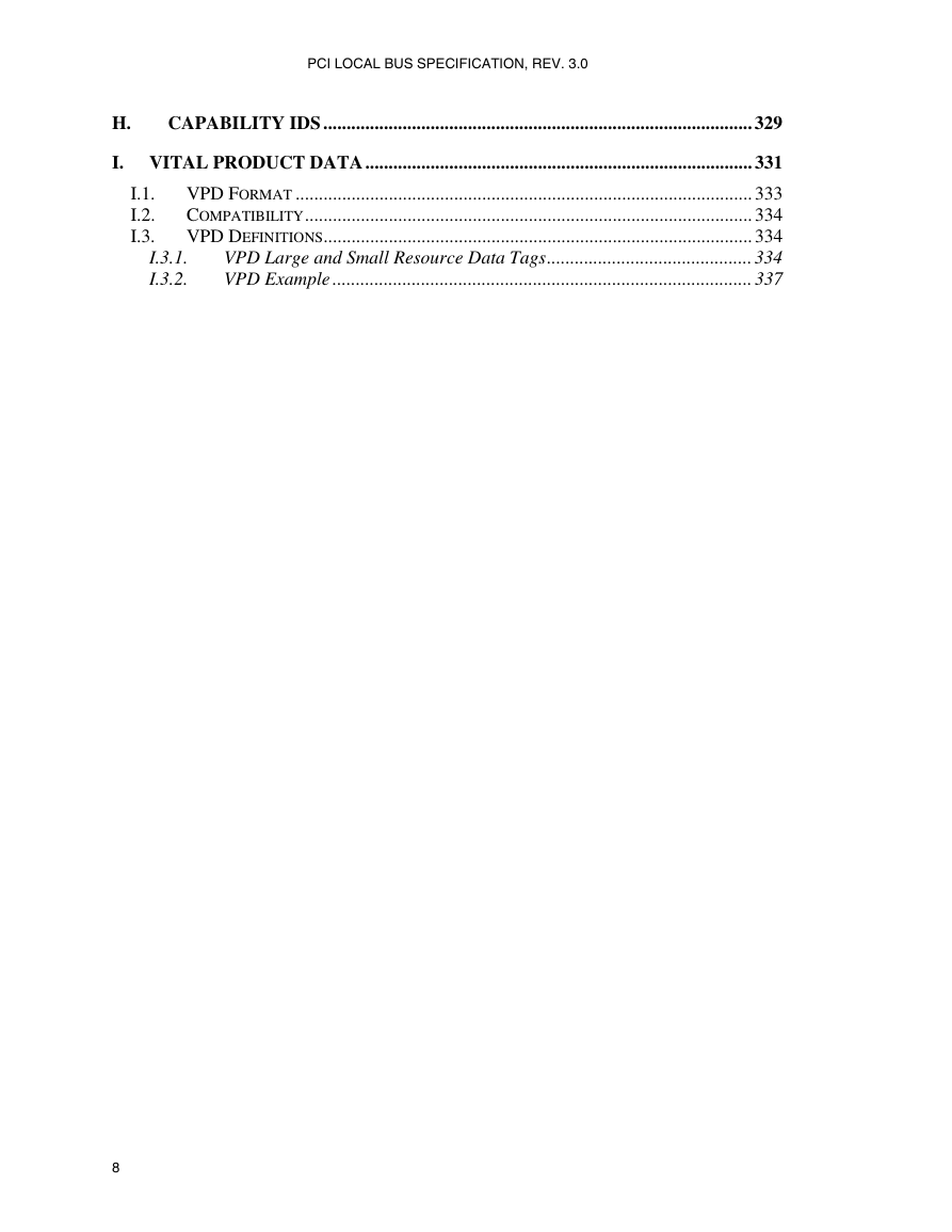
PCI LOCAL BUS SPECIFICATION, REV. 3.0 H. CAPABILITY IDS ............................................................................................ 329 I. VITAL PRODUCT DATA ................................................................................... 331 I.1. VPD FORMAT .................................................................................................. 333 I.2. COMPATIBILITY................................................................................................ 334 I.3. VPD DEFINITIONS............................................................................................ 334 VPD Large and Small Resource Data Tags............................................ 334 VPD Example .......................................................................................... 337 I.3.1. I.3.2. 8
分享到:
收藏