InvenSense Inc.
1197 Borregas Ave, Sunnyvale, CA 94089 U.S.A.
Tel: +1 (408) 988-7339 Fax: +1 (408) 988-8104
Website: www.invensense.com
Document Number: PS-MPU-6000A-00
Revision: 3.4
Release Date: 08/19/2013
MPU-6000 and MPU-6050
Product Specification
Revision 3.4
1 of 52
�
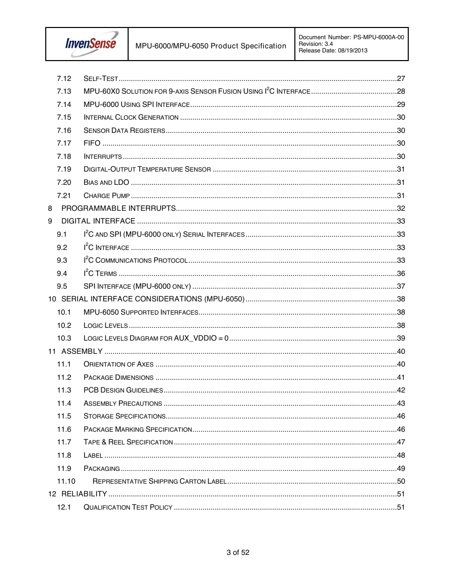
CONTENTS
MPU-6000/MPU-6050 Product Specification
Document Number: PS-MPU-6000A-00
Revision: 3.4
Release Date: 08/19/2013
1 REVISION HISTORY ................................................................................................................................... 5
2 PURPOSE AND SCOPE ............................................................................................................................. 6
3 PRODUCT OVERVIEW ............................................................................................................................... 7
3.1
MPU-60X0 OVERVIEW ........................................................................................................................ 7
4 APPLICATIONS ........................................................................................................................................... 9
5 FEATURES ................................................................................................................................................ 10
5.1
5.2
5.3
5.4
5.5
GYROSCOPE FEATURES ..................................................................................................................... 10
ACCELEROMETER FEATURES ............................................................................................................. 10
ADDITIONAL FEATURES ...................................................................................................................... 10
MOTIONPROCESSING ......................................................................................................................... 11
CLOCKING ......................................................................................................................................... 11
6 ELECTRICAL CHARACTERISTICS ......................................................................................................... 12
6.1
6.2
6.3
6.4
6.5
6.6
6.7
6.8
6.9
GYROSCOPE SPECIFICATIONS ............................................................................................................ 12
ACCELEROMETER SPECIFICATIONS ..................................................................................................... 13
ELECTRICAL AND OTHER COMMON SPECIFICATIONS ............................................................................ 14
ELECTRICAL SPECIFICATIONS, CONTINUED ......................................................................................... 15
ELECTRICAL SPECIFICATIONS, CONTINUED ......................................................................................... 16
ELECTRICAL SPECIFICATIONS, CONTINUED ......................................................................................... 17
I2C TIMING CHARACTERIZATION.......................................................................................................... 18
SPI TIMING CHARACTERIZATION (MPU-6000 ONLY) ........................................................................... 19
ABSOLUTE MAXIMUM RATINGS ........................................................................................................... 20
7 APPLICATIONS INFORMATION .............................................................................................................. 21
7.1
7.2
7.3
7.4
7.5
7.6
7.7
7.8
7.9
7.10
7.11
PIN OUT AND SIGNAL DESCRIPTION .................................................................................................... 21
TYPICAL OPERATING CIRCUIT ............................................................................................................. 22
BILL OF MATERIALS FOR EXTERNAL COMPONENTS .............................................................................. 22
RECOMMENDED POWER-ON PROCEDURE ........................................................................................... 23
BLOCK DIAGRAM ............................................................................................................................... 24
OVERVIEW ........................................................................................................................................ 24
THREE-AXIS MEMS GYROSCOPE WITH 16-BIT ADCS AND SIGNAL CONDITIONING ................................ 25
THREE-AXIS MEMS ACCELEROMETER WITH 16-BIT ADCS AND SIGNAL CONDITIONING ........................ 25
DIGITAL MOTION PROCESSOR ............................................................................................................ 25
PRIMARY I2C AND SPI SERIAL COMMUNICATIONS INTERFACES ............................................................ 25
AUXILIARY I2C SERIAL INTERFACE ...................................................................................................... 26
2 of 52
�
MPU-6000/MPU-6050 Product Specification
Document Number: PS-MPU-6000A-00
Revision: 3.4
Release Date: 08/19/2013
7.12
SELF-TEST ........................................................................................................................................ 27
7.13 MPU-60X0 SOLUTION FOR 9-AXIS SENSOR FUSION USING I2C INTERFACE .......................................... 28
7.14 MPU-6000 USING SPI INTERFACE ..................................................................................................... 29
7.15
7.16
7.17
7.18
INTERNAL CLOCK GENERATION .......................................................................................................... 30
SENSOR DATA REGISTERS ................................................................................................................. 30
FIFO ................................................................................................................................................ 30
INTERRUPTS ...................................................................................................................................... 30
7.19 DIGITAL-OUTPUT TEMPERATURE SENSOR .......................................................................................... 31
7.20
BIAS AND LDO .................................................................................................................................. 31
7.21 CHARGE PUMP .................................................................................................................................. 31
8 PROGRAMMABLE INTERRUPTS ............................................................................................................ 32
9.1
9 DIGITAL INTERFACE ............................................................................................................................... 33
I2C AND SPI (MPU-6000 ONLY) SERIAL INTERFACES .......................................................................... 33
I2C INTERFACE .................................................................................................................................. 33
I2C COMMUNICATIONS PROTOCOL ...................................................................................................... 33
I2C TERMS ........................................................................................................................................ 36
9.2
9.3
9.4
9.5
SPI INTERFACE (MPU-6000 ONLY) .................................................................................................... 37
10 SERIAL INTERFACE CONSIDERATIONS (MPU-6050) .......................................................................... 38
10.1 MPU-6050 SUPPORTED INTERFACES ................................................................................................. 38
10.2
10.3
LOGIC LEVELS ................................................................................................................................... 38
LOGIC LEVELS DIAGRAM FOR AUX_VDDIO = 0 .................................................................................. 39
11 ASSEMBLY ............................................................................................................................................... 40
11.1 ORIENTATION OF AXES ...................................................................................................................... 40
11.2
11.3
11.4
11.5
11.6
11.7
11.8
11.9
PACKAGE DIMENSIONS ...................................................................................................................... 41
PCB DESIGN GUIDELINES .................................................................................................................. 42
ASSEMBLY PRECAUTIONS .................................................................................................................. 43
STORAGE SPECIFICATIONS ................................................................................................................. 46
PACKAGE MARKING SPECIFICATION .................................................................................................... 46
TAPE & REEL SPECIFICATION ............................................................................................................. 47
LABEL ............................................................................................................................................... 48
PACKAGING ....................................................................................................................................... 49
11.10
REPRESENTATIVE SHIPPING CARTON LABEL ................................................................................... 50
12 RELIABILITY ............................................................................................................................................. 51
12.1 QUALIFICATION TEST POLICY ............................................................................................................. 51
3 of 52
�
MPU-6000/MPU-6050 Product Specification
Document Number: PS-MPU-6000A-00
Revision: 3.4
Release Date: 08/19/2013
12.2 QUALIFICATION TEST PLAN ................................................................................................................ 51
13 ENVIRONMENTAL COMPLIANCE ........................................................................................................... 52
4 of 52
�
MPU-6000/MPU-6050 Product Specification
Document Number: PS-MPU-6000A-00
Revision: 3.4
Release Date: 08/19/2013
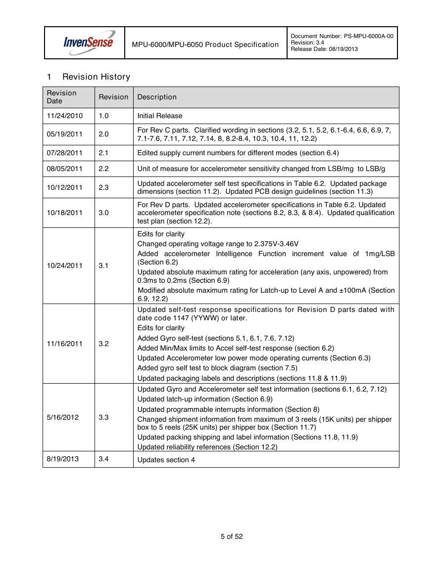
1 Revision History
Revision
Date
Revision Description
11/24/2010
1.0
Initial Release
05/19/2011
2.0
For Rev C parts. Clarified wording in sections (3.2, 5.1, 5.2, 6.1-6.4, 6.6, 6.9, 7,
7.1-7.6, 7.11, 7.12, 7.14, 8, 8.2-8.4, 10.3, 10.4, 11, 12.2)
07/28/2011
2.1
Edited supply current numbers for different modes (section 6.4)
08/05/2011
2.2
Unit of measure for accelerometer sensitivity changed from LSB/mg to LSB/g
10/12/2011
2.3
Updated accelerometer self test specifications in Table 6.2. Updated package
dimensions (section 11.2). Updated PCB design guidelines (section 11.3)
10/18/2011
3.0
10/24/2011
3.1
11/16/2011
3.2
5/16/2012
3.3
For Rev D parts. Updated accelerometer specifications in Table 6.2. Updated
accelerometer specification note (sections 8.2, 8.3, & 8.4). Updated qualification
test plan (section 12.2).
Edits for clarity
Changed operating voltage range to 2.375V-3.46V
Added accelerometer Intelligence Function increment value of 1mg/LSB
(Section 6.2)
Updated absolute maximum rating for acceleration (any axis, unpowered) from
0.3ms to 0.2ms (Section 6.9)
Modified absolute maximum rating for Latch-up to Level A and ±100mA (Section
6.9, 12.2)
Updated self-test response specifications for Revision D parts dated with
date code 1147 (YYWW) or later.
Edits for clarity
Added Gyro self-test (sections 5.1, 6.1, 7.6, 7.12)
Added Min/Max limits to Accel self-test response (section 6.2)
Updated Accelerometer low power mode operating currents (Section 6.3)
Added gyro self test to block diagram (section 7.5)
Updated packaging labels and descriptions (sections 11.8 & 11.9)
Updated Gyro and Accelerometer self test information (sections 6.1, 6.2, 7.12)
Updated latch-up information (Section 6.9)
Updated programmable interrupts information (Section 8)
Changed shipment information from maximum of 3 reels (15K units) per shipper
box to 5 reels (25K units) per shipper box (Section 11.7)
Updated packing shipping and label information (Sections 11.8, 11.9)
Updated reliability references (Section 12.2)
8/19/2013
3.4
Updates section 4
5 of 52
�
MPU-6000/MPU-6050 Product Specification
Document Number: PS-MPU-6000A-00
Revision: 3.4
Release Date: 08/19/2013
2 Purpose and Scope
This product specification provides advanced information regarding the electrical specification and design
related information for the MPU-6000™ and MPU-6050™ MotionTracking™ devices, collectively called the
MPU-60X0™ or MPU™.
Electrical characteristics are based upon design analysis and simulation results only. Specifications are
subject to change without notice. Final specifications will be updated based upon characterization of
production silicon. For references to register map and descriptions of individual registers, please refer to the
MPU-6000/MPU-6050 Register Map and Register Descriptions document.
The self-test response specifications provided in this document pertain to Revision D parts with date
codes of 1147 (YYWW) or later. Please see Section 11.6 for package marking description details.
6 of 52
�
MPU-6000/MPU-6050 Product Specification
Document Number: PS-MPU-6000A-00
Revision: 3.4
Release Date: 08/19/2013
3 Product Overview
is becoming a “must-have”
function being adopted by smartphone and
3.1 MPU-60X0 Overview
MotionInterface™
tablet
manufacturers due to the enormous value it adds to the end user experience. In smartphones, it finds use in
applications such as gesture commands for applications and phone control, enhanced gaming, augmented
reality, panoramic photo capture and viewing, and pedestrian and vehicle navigation. With its ability to
precisely and accurately track user motions, MotionTracking technology can convert handsets and tablets
into powerful 3D intelligent devices that can be used in applications ranging from health and fitness
monitoring to location-based services. Key requirements for MotionInterface enabled devices are small
package size, low power consumption, high accuracy and repeatability, high shock tolerance, and application
specific performance programmability – all at a low consumer price point.
The MPU-60X0 is the world’s first integrated 6-axis MotionTracking device that combines a 3-axis
gyroscope, 3-axis accelerometer, and a Digital Motion Processor™ (DMP) all in a small 4x4x0.9mm
package. With its dedicated I2C sensor bus, it directly accepts inputs from an external 3-axis compass to
provide a complete 9-axis MotionFusion™ output. The MPU-60X0 MotionTracking device, with its 6-axis
integration, on-board MotionFusion™, and run-time calibration firmware, enables manufacturers to eliminate
the costly and complex selection, qualification, and system level integration of discrete devices, guaranteeing
optimal motion performance for consumers. The MPU-60X0 is also designed to interface with multiple non-
inertial digital sensors, such as pressure sensors, on its auxiliary I2C port. The MPU-60X0 is footprint
compatible with the MPU-30X0 family.
The MPU-60X0 features three 16-bit analog-to-digital converters (ADCs) for digitizing the gyroscope outputs
and three 16-bit ADCs for digitizing the accelerometer outputs. For precision tracking of both fast and slow
motions, the parts feature a user-programmable gyroscope full-scale range of ±250, ±500, ±1000, and
±2000°/sec (dps) and a user-programmable accelerometer full-scale range of ±2g, ±4g, ±8g, and ±16g.
An on-chip 1024 Byte FIFO buffer helps lower system power consumption by allowing the system processor
to read the sensor data in bursts and then enter a low-power mode as the MPU collects more data. With all
the necessary on-chip processing and sensor components required to support many motion-based use
cases, the MPU-60X0 uniquely enables low-power MotionInterface applications in portable applications with
reduced processing requirements for the system processor. By providing an integrated MotionFusion output,
the DMP in the MPU-60X0 offloads the intensive MotionProcessing computation requirements from the
system processor, minimizing the need for frequent polling of the motion sensor output.
Communication with all registers of the device is performed using either I2C at 400kHz or SPI at 1MHz
(MPU-6000 only). For applications requiring faster communications, the sensor and interrupt registers may
be read using SPI at 20MHz (MPU-6000 only). Additional features include an embedded temperature sensor
and an on-chip oscillator with ±1% variation over the operating temperature range.
By leveraging its patented and volume-proven Nasiri-Fabrication platform, which integrates MEMS wafers
with companion CMOS electronics through wafer-level bonding, InvenSense has driven the MPU-60X0
package size down to a revolutionary footprint of 4x4x0.9mm (QFN), while providing the highest
performance, lowest noise, and the lowest cost semiconductor packaging required for handheld consumer
electronic devices. The part features a robust 10,000g shock tolerance, and has programmable low-pass
filters for the gyroscopes, accelerometers, and the on-chip temperature sensor.
For power supply flexibility, the MPU-60X0 operates from VDD power supply voltage range of 2.375V-3.46V.
Additionally, the MPU-6050 provides a VLOGIC reference pin (in addition to its analog supply pin: VDD),
which sets the logic levels of its I2C interface. The VLOGIC voltage may be 1.8V±5% or VDD.
The MPU-6000 and MPU-6050 are identical, except that the MPU-6050 supports the I2C serial interface only,
and has a separate VLOGIC reference pin. The MPU-6000 supports both I2C and SPI interfaces and has a
single supply pin, VDD, which is both the device’s logic reference supply and the analog supply for the part.
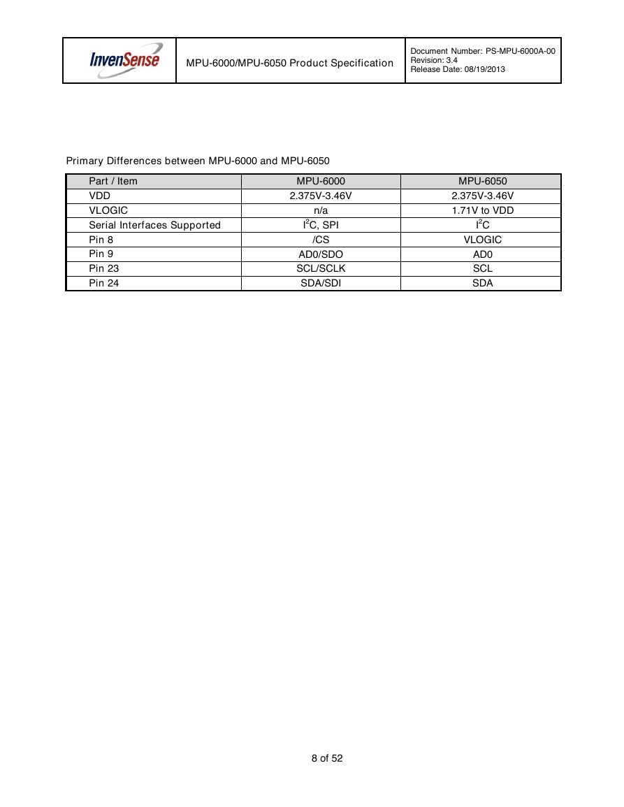
The table below outlines these differences:
7 of 52
�
MPU-6000/MPU-6050 Product Specification
Document Number: PS-MPU-6000A-00
Revision: 3.4
Release Date: 08/19/2013
Primary Differences between MPU-6000 and MPU-6050
Part / Item
VDD
VLOGIC
Serial Interfaces Supported
Pin 8
Pin 9
Pin 23
Pin 24
MPU-6000
2.375V-3.46V
n/a
I2C, SPI
/CS
AD0/SDO
SCL/SCLK
SDA/SDI
MPU-6050
2.375V-3.46V
1.71V to VDD
I2C
VLOGIC
AD0
SCL
SDA
8 of 52
�







 uCOS-III的任务调度算法研究.pdf
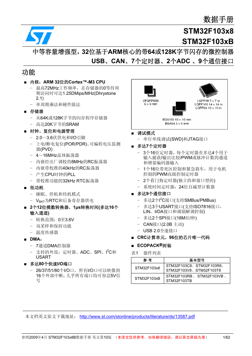 STM32F103x8B_DS_CH_V10(7STM32中文数据手册).pdf
 FX2N系列PLC培训教程.pdf
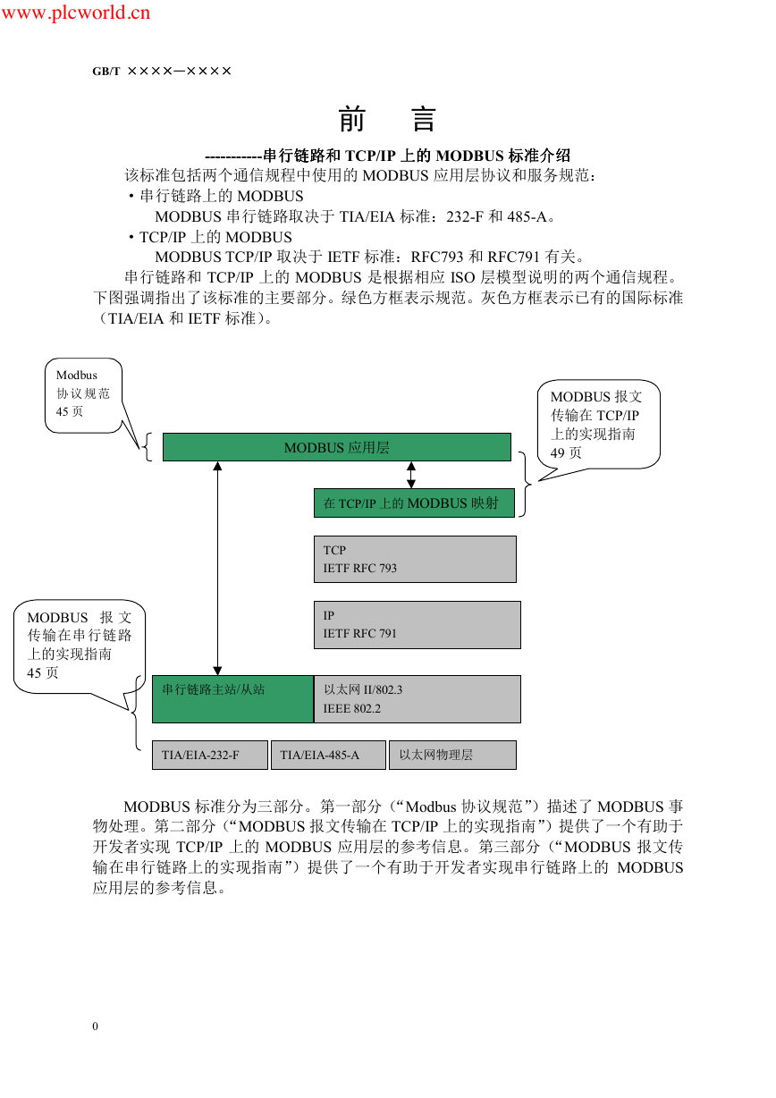 Modbus协议资料.pdf
 WM8978中文资料(芯片资料).doc
 5-1.【Codelab】HarmonyOS基于图像模块实现图库图片的四种常见操作.pdf
 GX Developer 编程软件使用说明.pdf
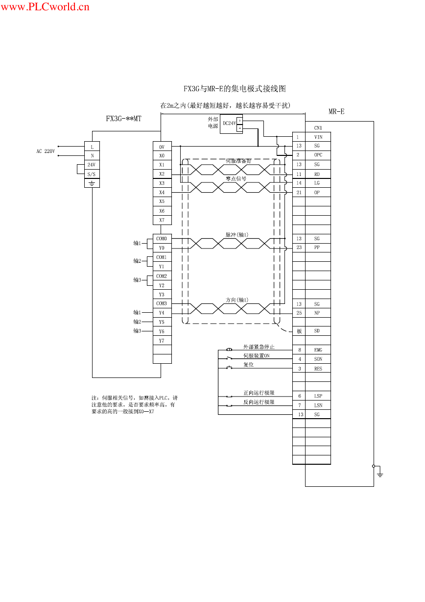 MR-E伺服与FX3G接线图.pdf
 ATK-NEO-6M GPS模块常见问题汇总_201400721.pdf
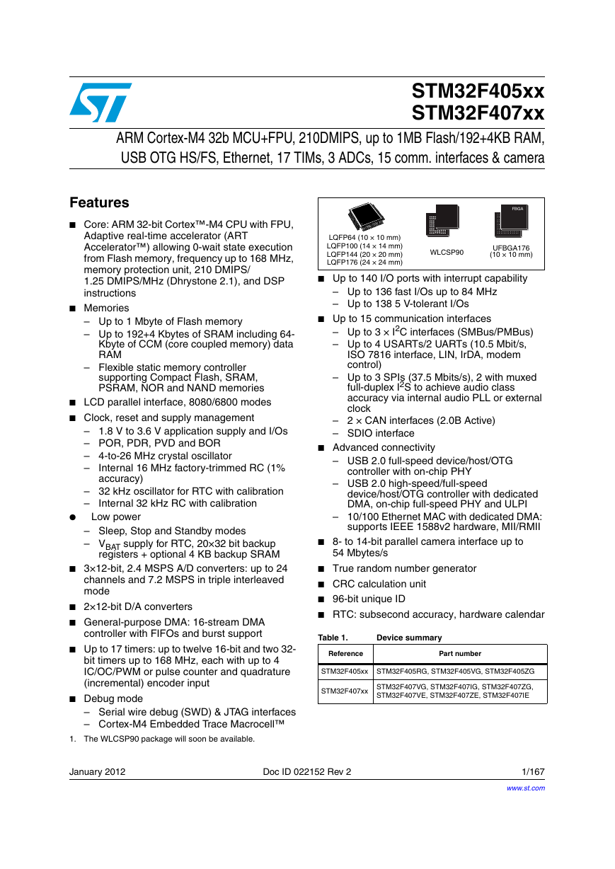 STM32F407ZGT6(芯片资料).pdf
 FM1715编程指南.pdf
 Profibus教程-7.PROFIBUS-FMS.pdf