OOTTTT22000011AA
TToouucchh AApppplliiccaattiioonn NNoottee
II22CC PPrroottooccooll GGuuiiddee
Preliminary
Aug. 20, 2013
�
Solution Depot Limited I2C Protocol Guide
Table of Content
Introduction............................................................................................................................................3
I2C Interface Protocol............................................................................................................................4
2.1
2.2
2.3
2.4
Timing Characteristic ................................................................................................................4
I2C Buffer and Data Format......................................................................................................5
Function Description .................................................................................................................6
Operation Definition..................................................................................................................7
I2C R/W Timing Table .................................................................................................7
Touch event....................................................................................................................8
Setting TP On/Off ..........................................................................................................9
2.4.1
2.4.2
2.4.3
1
2
本资料问新励科技专有之财产,非经书面许可,不准透露或使用本数据,亦不准复印、复制或转变为任何其它型式使用。
The information contained herein is the exclusive property of Solution Depot Limited. and shall not be distributed, reproduced, or disclosed in whole or in
part without prior written permission of Solution Depot Limited.
Page 2 of 9
�
Solution Depot Limited I2C Protocol Guide
1 Introduction
The OTT2001A, a 208 channels capacitive touch driver LSI, is designed for up to7” passive matrix touch module. When users touch module by
finger, the module can send coordinates of point at the contact point to host. The finger position information is sent to host by I2C bus which is
determined by host through INT line. The purpose of this guide is to introduce the I2C protocol in detail.
本资料问新励科技专有之财产,非经书面许可,不准透露或使用本数据,亦不准复印、复制或转变为任何其它型式使用。
The information contained herein is the exclusive property of Solution Depot Limited. and shall not be distributed, reproduced, or disclosed in whole or in
part without prior written permission of Solution Depot Limited.
Page 3 of 9
�
Solution Depot Limited I2C Protocol Guide
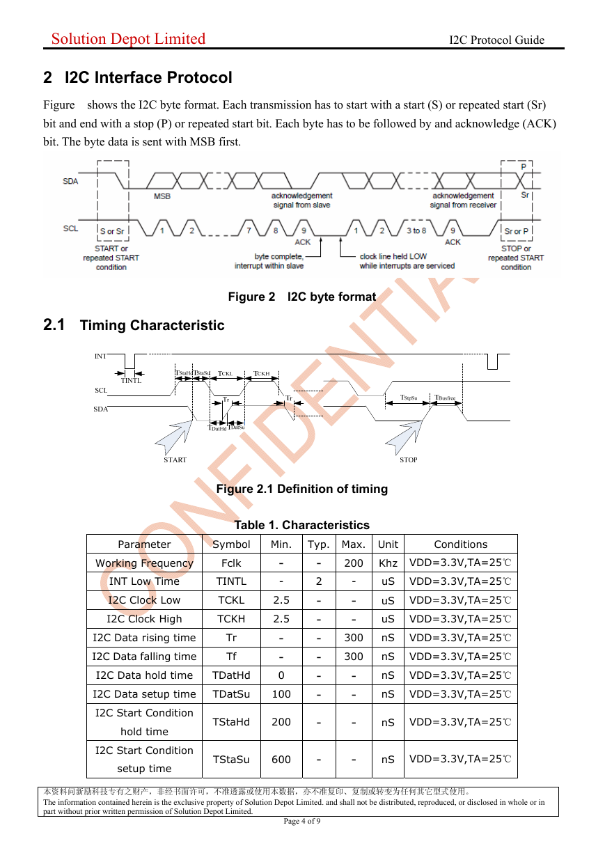
2 I2C Interface Protocol
Figure shows the I2C byte format. Each transmission has to start with a start (S) or repeated start (Sr)
bit and end with a stop (P) or repeated start bit. Each byte has to be followed by and acknowledge (ACK)
bit. The byte data is sent with MSB first.
2.1 Timing Characteristic
Figure 2 I2C byte format
Figure 2.1 Definition of timing
Table 1. Characteristics
Parameter
Symbol Min. Typ. Max. Unit
Conditions
Working Frequency
Fclk
INT Low Time
I2C Clock Low
I2C Clock High
TINTL
TCKL
TCKH
I2C Data rising time
I2C Data falling time
Tr
Tf
I2C Data hold time
TDatHd
-
-
2.5
2.5
-
-
0
I2C Data setup time
TDatSu
100
I2C Start Condition
hold time
I2C Start Condition
setup time
TStaHd
200
TStaSu
600
-
2
-
-
-
-
-
-
-
-
-
-
-
300
200 Khz VDD=3.3V,TA=25℃
uS VDD=3.3V,TA=25℃
uS VDD=3.3V,TA=25℃
uS VDD=3.3V,TA=25℃
nS VDD=3.3V,TA=25℃
nS VDD=3.3V,TA=25℃
nS VDD=3.3V,TA=25℃
nS VDD=3.3V,TA=25℃
300
-
-
-
-
nS VDD=3.3V,TA=25℃
nS VDD=3.3V,TA=25℃
本资料问新励科技专有之财产,非经书面许可,不准透露或使用本数据,亦不准复印、复制或转变为任何其它型式使用。
The information contained herein is the exclusive property of Solution Depot Limited. and shall not be distributed, reproduced, or disclosed in whole or in
part without prior written permission of Solution Depot Limited.
Page 4 of 9
�
Solution Depot Limited I2C Protocol Guide
I2C Stop Condition
setup time
TStpSu
600
I2C Bus free time
TBusFree
2.5
-
-
-
-
nS VDD=3.3V,TA=25℃
uS VDD=3.3V,TA=25℃
2.2
I2C Buffer and Data Format
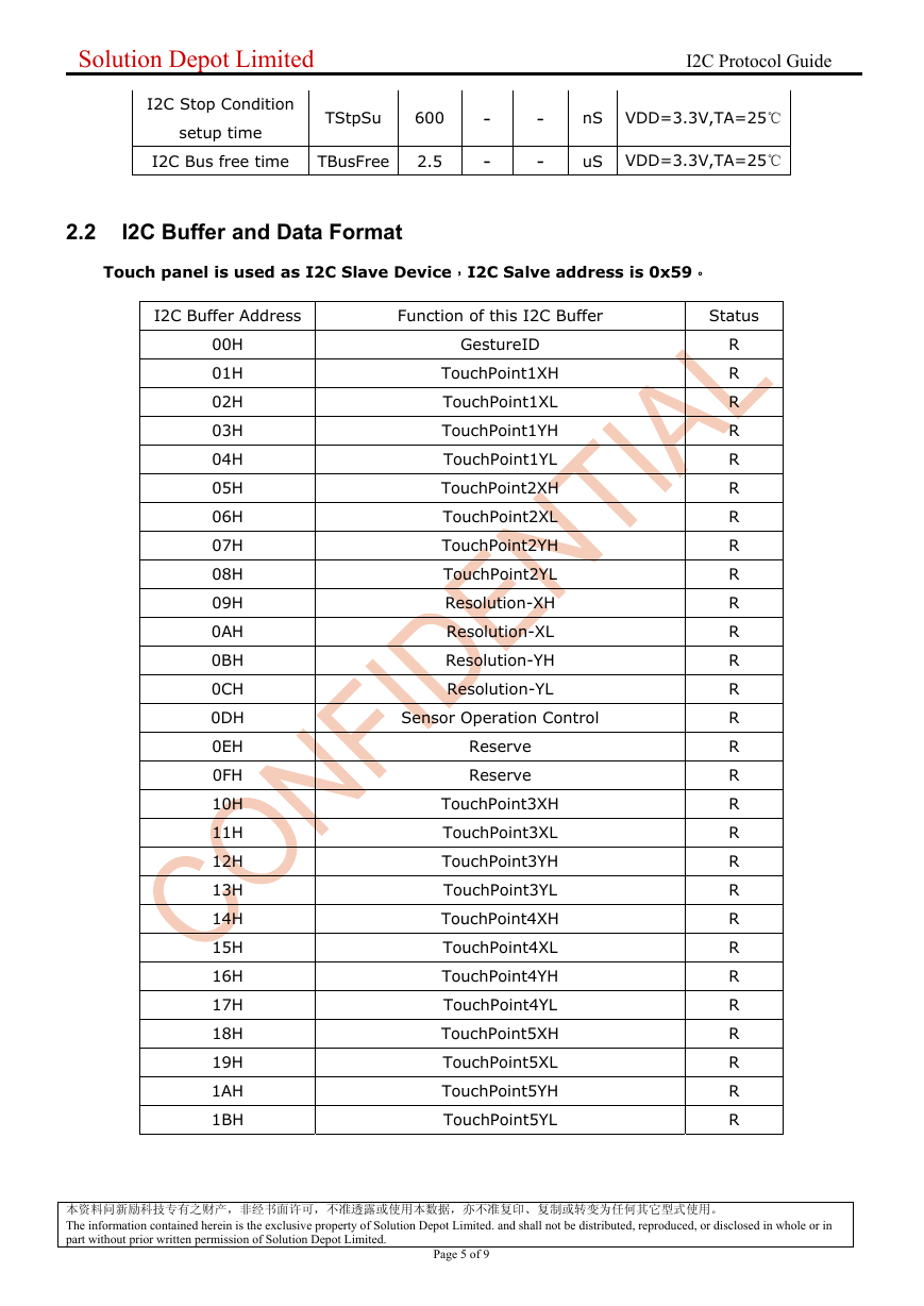
Touch panel is used as I2C Slave Device,I2C Salve address is 0x59。
I2C Buffer Address
Function of this I2C Buffer
Status
00H
01H
02H
03H
04H
05H
06H
07H
08H
09H
0AH
0BH
0CH
0DH
0EH
0FH
10H
11H
12H
13H
14H
15H
16H
17H
18H
19H
1AH
1BH
GestureID
TouchPoint1XH
TouchPoint1XL
TouchPoint1YH
TouchPoint1YL
TouchPoint2XH
TouchPoint2XL
TouchPoint2YH
TouchPoint2YL
Resolution-XH
Resolution-XL
Resolution-YH
Resolution-YL
Sensor Operation Control
Reserve
Reserve
TouchPoint3XH
TouchPoint3XL
TouchPoint3YH
TouchPoint3YL
TouchPoint4XH
TouchPoint4XL
TouchPoint4YH
TouchPoint4YL
TouchPoint5XH
TouchPoint5XL
TouchPoint5YH
TouchPoint5YL
R
R
R
R
R
R
R
R
R
R
R
R
R
R
R
R
R
R
R
R
R
R
R
R
R
R
R
R
本资料问新励科技专有之财产,非经书面许可,不准透露或使用本数据,亦不准复印、复制或转变为任何其它型式使用。
The information contained herein is the exclusive property of Solution Depot Limited. and shall not be distributed, reproduced, or disclosed in whole or in
part without prior written permission of Solution Depot Limited.
Page 5 of 9
�
Solution Depot Limited I2C Protocol Guide
2.3 Function Description
I2C Buffer Address
Bit
Function Description
Status
00H
7…0 Gesture ID
0
1
2
3
4
0x00: finger leave
1:coordinator (X1,Y1) valid
0:coordinator (X1,Y1) invalid
1:coordinator (X2,Y2) valid
0:coordinator (X2,Y2) invalid
1:coordinator (X3,Y3) valid
0:coordinator (X3,Y3) invalid
1:coordinator (X4,Y4) valid
0:coordinator (X4,Y4) invalid
1:coordinator (X5,Y5) valid
0:coordinator (X5,Y5) invalid
7..5
Reserve
01H
02H
03H
04H
05H
06H
07H
08H
09H
0AH
0BH
0CH
X1[15:8]
X1[7:0]
Y1[15:8]
Y1[7:0]
X2[15:8]
X2[7:0]
Y2[15:8]
Y2[7:0]
Resolution1
Resolution2
Resolution3
Resolution4
Bit
Power mode control register
0DH
7
Sensor On/Off Control
0:Disable Sensor
1:Enable Sensor(Default)
6..0
Reserve
0EH
0FH
10H
11H
12H
13H
Reserve
Reserve
X3[15:8]
X3[7:0]
Y3[15:8]
Y3[7:0]
R
R
R
R
R
R
R
R
R
R
R
R
R
R
R
R
R
R
R
R/W
R
R
R
R
R
R
本资料问新励科技专有之财产,非经书面许可,不准透露或使用本数据,亦不准复印、复制或转变为任何其它型式使用。
The information contained herein is the exclusive property of Solution Depot Limited. and shall not be distributed, reproduced, or disclosed in whole or in
part without prior written permission of Solution Depot Limited.
Page 6 of 9
�
Solution Depot Limited I2C Protocol Guide
14H
15H
16H
17H
18H
19H
1AH
1BH
X4[15:8]
X4[7:0]
Y4[15:8]
Y4[7:0]
X5[15:8]
X5[7:0]
Y5[15:8]
Y5[7:0]
R
R
R
R
R
R
R
R
2.4 Operation Definition
2.4.1 I2C R/W Timing Table
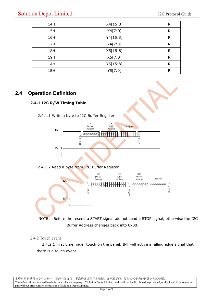
2.4.1.1 Write a byte to I2C Buffer Register
A
6
A
5
A
4
A
3
A
2
A
1
A
0 XXXXXXXX XXXXXXXX
W
(
0
)
S
T
A
R
T
S
T
O
P
2.4.1.2 Read a byte from I2C Buffer Register
I2C
INT 1
0
I2C
Device
Address
I2C
Buffer
Address
I2C
Device
Address
A
6
A
5
A
4
A
3
A
2
A
1
A
0
R
(
1
)
A
6
A
5
A
4
A
3
A
2
A
1
A
0 XXXXXXXX
W
(
0
)
S
T
A
R
T
S
T
A
R
T
Register
XXXXXXXX
S
T
O
P
NOTE: Before the resend a START signal ,do not send a STOP signal, otherwise the I2C
Buffer Address changes back into 0x00.
2.4.2 Touch event
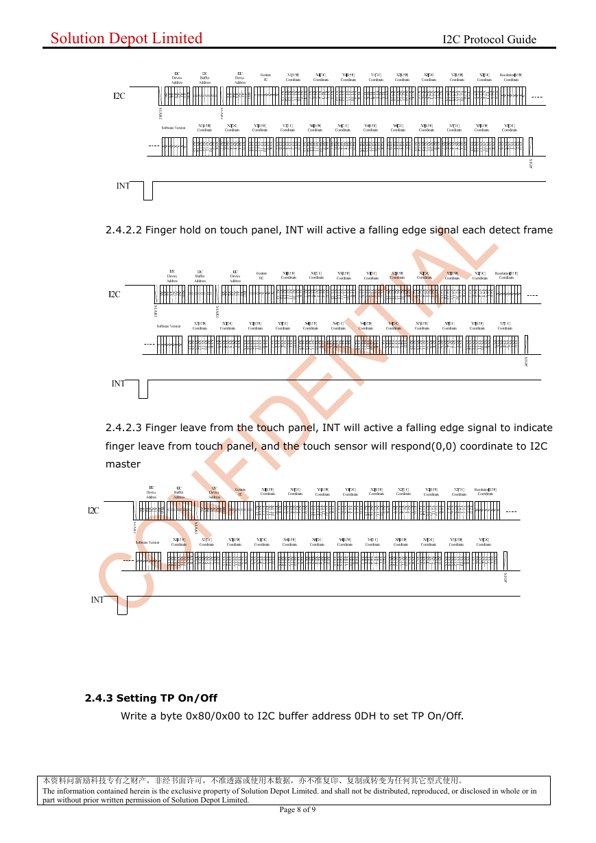
2.4.2.1 First time finger touch on the panel, INT will active a falling edge signal that
there is a touch event.
本资料问新励科技专有之财产,非经书面许可,不准透露或使用本数据,亦不准复印、复制或转变为任何其它型式使用。
The information contained herein is the exclusive property of Solution Depot Limited. and shall not be distributed, reproduced, or disclosed in whole or in
part without prior written permission of Solution Depot Limited.
Page 7 of 9
�
Solution Depot Limited I2C Protocol Guide
2.4.2.2 Finger hold on touch panel, INT will active a falling edge signal each detect frame
2.4.2.3 Finger leave from the touch panel, INT will active a falling edge signal to indicate
finger leave from touch panel, and the touch sensor will respond(0,0) coordinate to I2C
master
2.4.3 Setting TP On/Off
Write a byte 0x80/0x00 to I2C buffer address 0DH to set TP On/Off.
本资料问新励科技专有之财产,非经书面许可,不准透露或使用本数据,亦不准复印、复制或转变为任何其它型式使用。
The information contained herein is the exclusive property of Solution Depot Limited. and shall not be distributed, reproduced, or disclosed in whole or in
part without prior written permission of Solution Depot Limited.
Page 8 of 9
�



 uCOS-III的任务调度算法研究.pdf
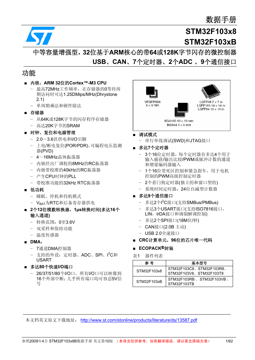 STM32F103x8B_DS_CH_V10(7STM32中文数据手册).pdf
 FX2N系列PLC培训教程.pdf
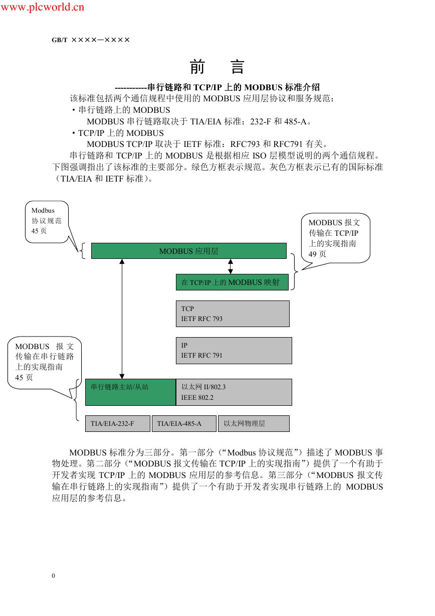 Modbus协议资料.pdf
 WM8978中文资料(芯片资料).doc
 5-1.【Codelab】HarmonyOS基于图像模块实现图库图片的四种常见操作.pdf
 GX Developer 编程软件使用说明.pdf
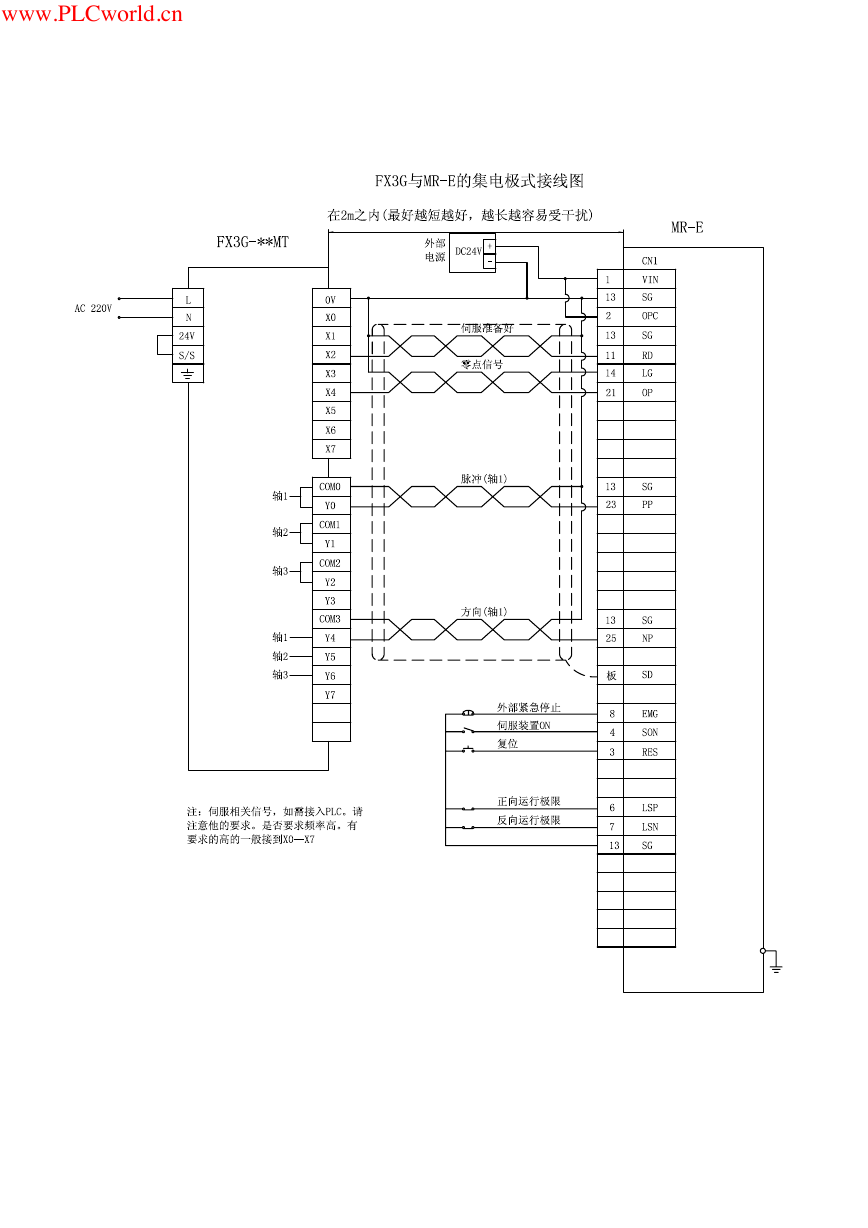 MR-E伺服与FX3G接线图.pdf
 ATK-NEO-6M GPS模块常见问题汇总_201400721.pdf
 STM32F407ZGT6(芯片资料).pdf
 FM1715编程指南.pdf
 Profibus教程-7.PROFIBUS-FMS.pdf