LTE PHY Spec.
Samsung Electronics
June 24, 2008
�
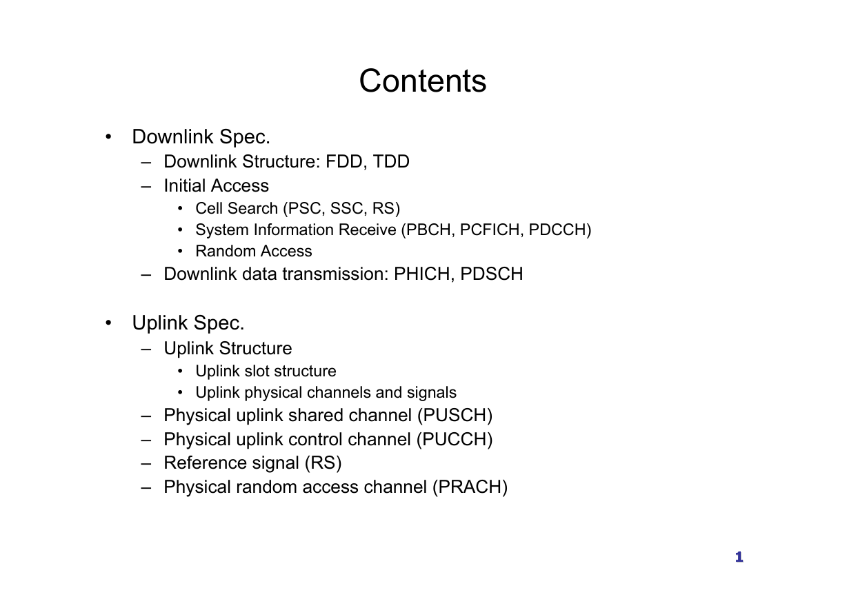
Contents
• Downlink Spec.
– Downlink Structure: FDD, TDD
– Initial Access
• Cell Search (PSC, SSC, RS)
• System Information Receive (PBCH, PCFICH, PDCCH)
• Random Access
– Downlink data transmission: PHICH, PDSCH
• Uplink Spec.
– Uplink Structure
• Uplink slot structure
• Uplink physical channels and signals
– Physical uplink shared channel (PUSCH)
– Physical uplink control channel (PUCCH)
– Reference signal (RS)
– Physical random access channel (PRACH)
1111
�
LTE L1 Specification
Downlink structure
22
�
Frame Structure
• Frame structure
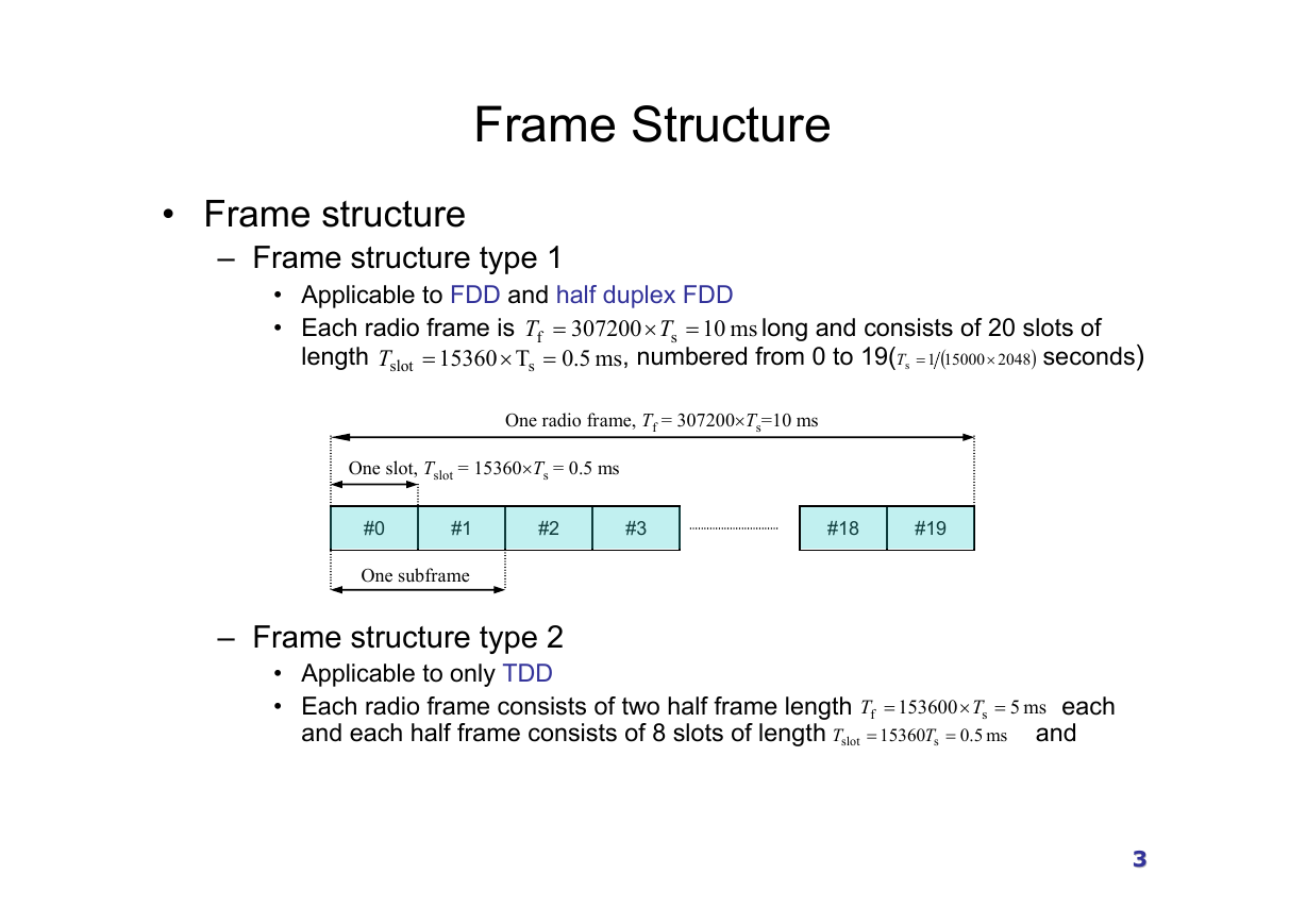
– Frame structure type 1
• Applicable to FDD and half duplex FDD
• Each radio frame is
T
f
T
×
s
307200
=
ms 5.0
=
length
15360
T
slot
T
s
=
×
=
ms 10
long and consists of 20 slots of
, numbered from 0 to 19( seconds)
(
15000
=T
s
2048
×
1
)
One radio frame, Tf = 307200×Ts=10 ms
One slot, Tslot = 15360×Ts = 0.5 ms
#0
#1
#2
#3
#18
#19
One subframe
– Frame structure type 2
• Applicable to only TDD
• Each radio frame consists of two half frame length
153600
=
and each half frame consists of 8 slots of length
T
15360 s
=
T
f
T
=
slot
T
=
×
s
ms 5.0
ms 5
each
and
33
�
Frame Structure
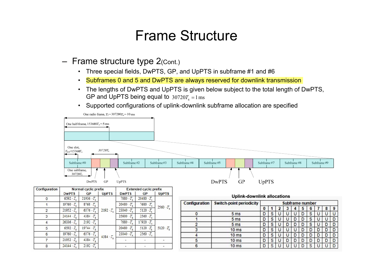
– Frame structure type 2(Cont.)
• Three special fields, DwPTS, GP, and UpPTS in subframe #1 and #6
• Subframes 0 and 5 and DwPTS are always reserved for downlink transmission
• The lengths of DwPTS and UpPTS is given below subject to the total length of DwPTS,
GP and UpPTS being equal to
ms 1
• Supported configurations of uplink-downlink subframe allocation are specified
0720
3
s =T
Lengths of DwPTS/GP/UpPTS
Lengths of DwPTS/GP/UpPTS
Uplink--downlink allocations
downlink allocations
Uplink
�
Downlink
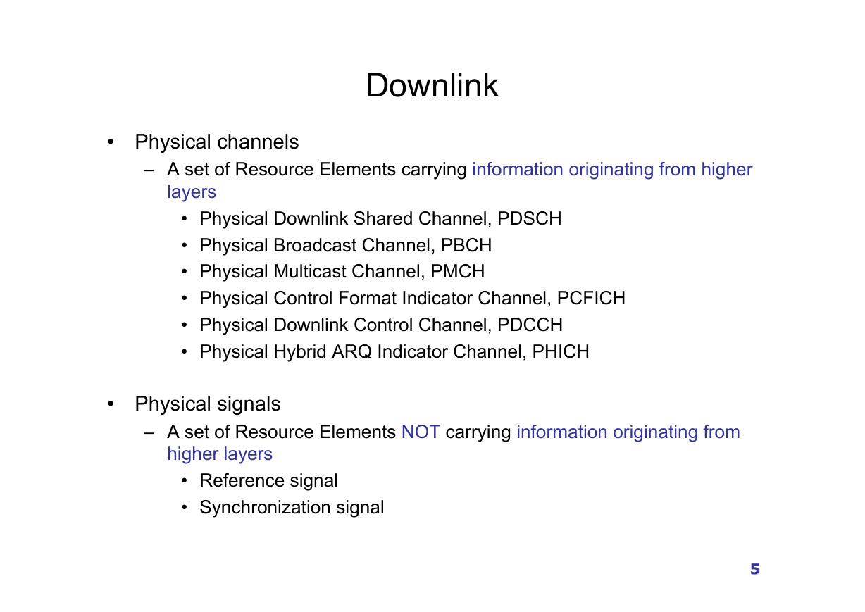
• Physical channels
– A set of Resource Elements carrying information originating from higher
layers
• Physical Downlink Shared Channel, PDSCH
• Physical Broadcast Channel, PBCH
• Physical Multicast Channel, PMCH
• Physical Control Format Indicator Channel, PCFICH
• Physical Downlink Control Channel, PDCCH
• Physical Hybrid ARQ Indicator Channel, PHICH
• Physical signals
– A set of Resource Elements NOT carrying information originating from
higher layers
• Reference signal
• Synchronization signal
55
�
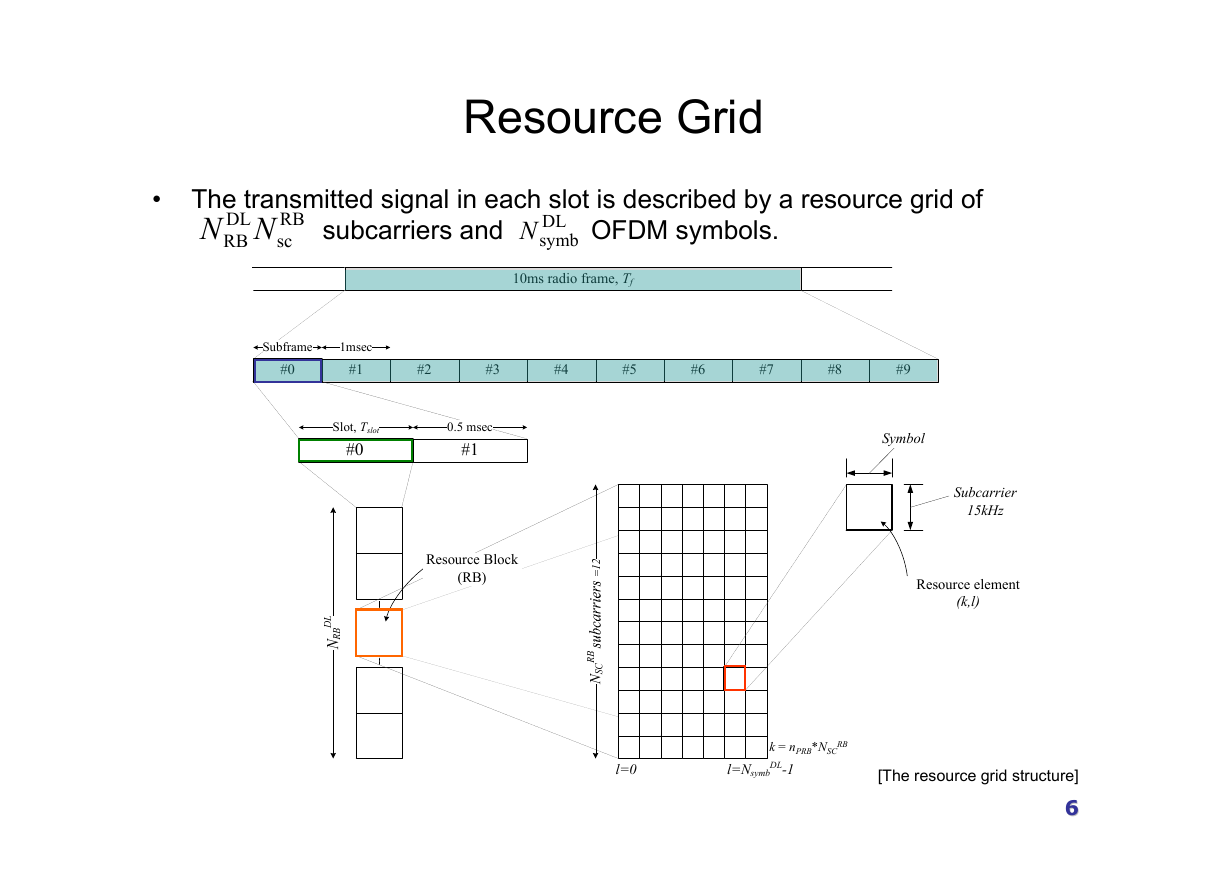
• The transmitted signal in each slot is described by a resource grid of
DL
RB NN
RB
sc
subcarriers and OFDM symbols.
Resource Grid
DL
symbN
10ms radio frame, Tf
Subframe
#0
1msec
#1
#2
#3
#4
#5
#6
#7
#8
#9
Slot, Tslot
#0
0.5 msec
#1
Resource Block
(RB)
l=0
Symbol
Subcarrier
15kHz
Resource element
(k,l)
[The resource grid structure]
66
*NSC
RB
k = nPRB
DL-1
l=Nsymb
�
Resource Grid
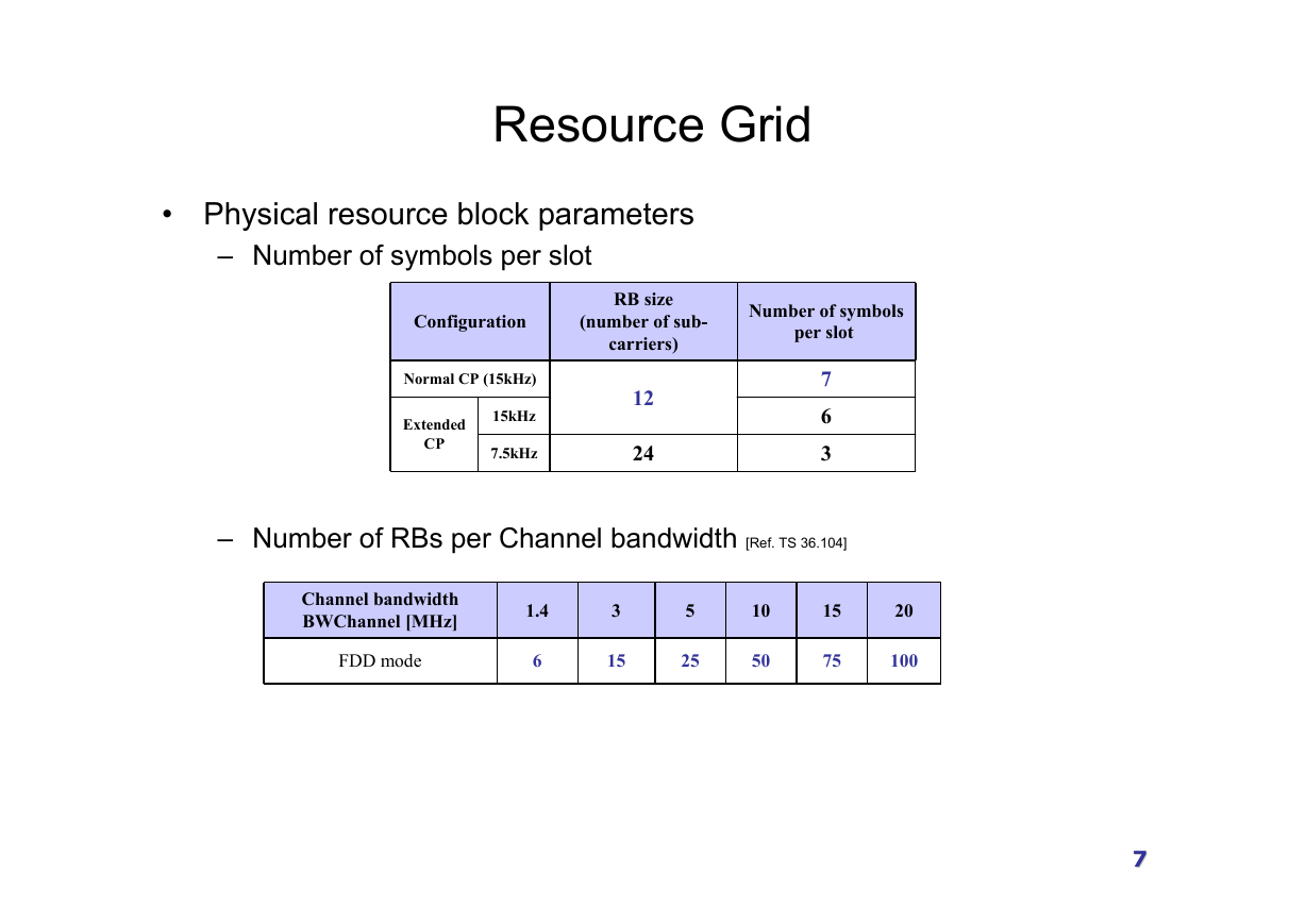
• Physical resource block parameters
– Number of symbols per slot
Configuration
Normal CP (15kHz)
Extended
CP
15kHz
7.5kHz
RB size
(number of sub-
carriers)
Number of symbols
per slot
12
24
7
6
3
– Number of RBs per Channel bandwidth [Ref. TS 36.104]
Channel bandwidth
BWChannel [MHz]
FDD mode
1.4
6
3
15
5
25
10
50
15
75
20
100
77
�



 2023年江西萍乡中考道德与法治真题及答案.doc
 2012年重庆南川中考生物真题及答案.doc
 2013年江西师范大学地理学综合及文艺理论基础考研真题.doc
 2020年四川甘孜小升初语文真题及答案I卷.doc
 2020年注册岩土工程师专业基础考试真题及答案.doc
 2023-2024学年福建省厦门市九年级上学期数学月考试题及答案.doc
 2021-2022学年辽宁省沈阳市大东区九年级上学期语文期末试题及答案.doc
 2022-2023学年北京东城区初三第一学期物理期末试卷及答案.doc
 2018上半年江西教师资格初中地理学科知识与教学能力真题及答案.doc
 2012年河北国家公务员申论考试真题及答案-省级.doc
 2020-2021学年江苏省扬州市江都区邵樊片九年级上学期数学第一次质量检测试题及答案.doc
 2022下半年黑龙江教师资格证中学综合素质真题及答案.doc