Serial ATA AHCI 1.1 Specification
Revision 1_1.doc
SSeerriiaall AATTAA
AAddvvaanncceedd HHoosstt CCoonnttrroolllleerr IInntteerrffaaccee
((AAHHCCII))
RReevviissiioonn 11..11
Revision 1_1.doc
Please send comments to Amber Huffman
amber.huffman@intel.com
i
�
Revision 1_1.doc
Serial ATA AHCI 1.1 Specification
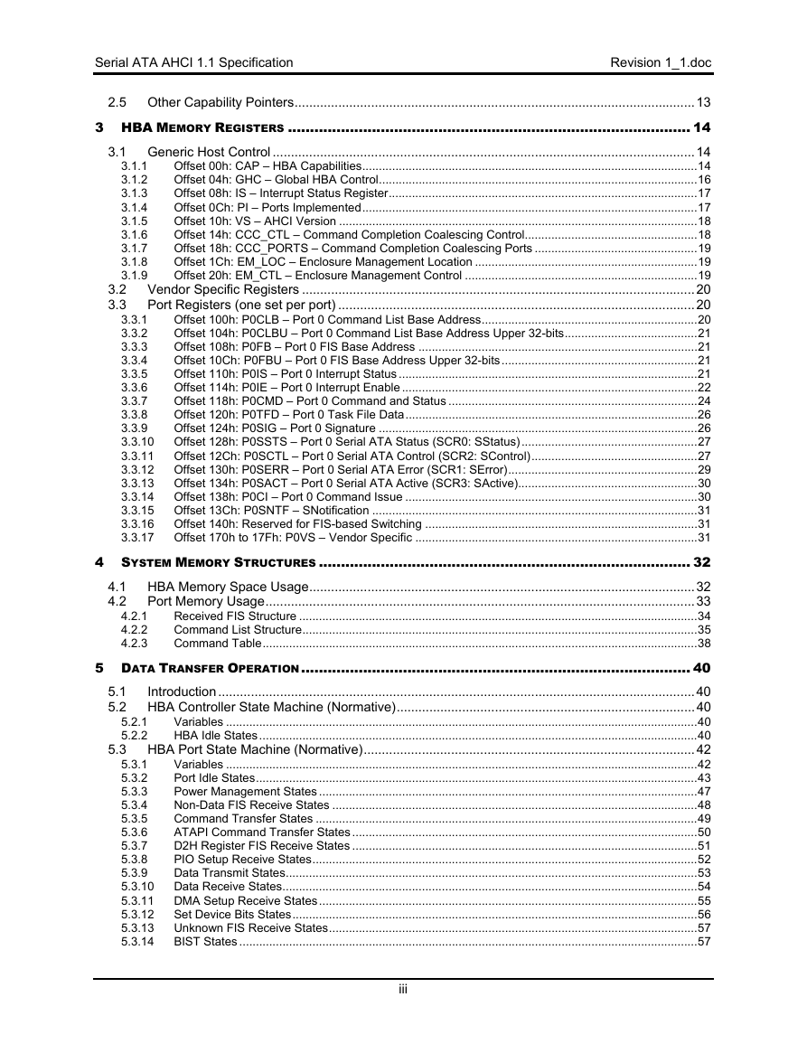
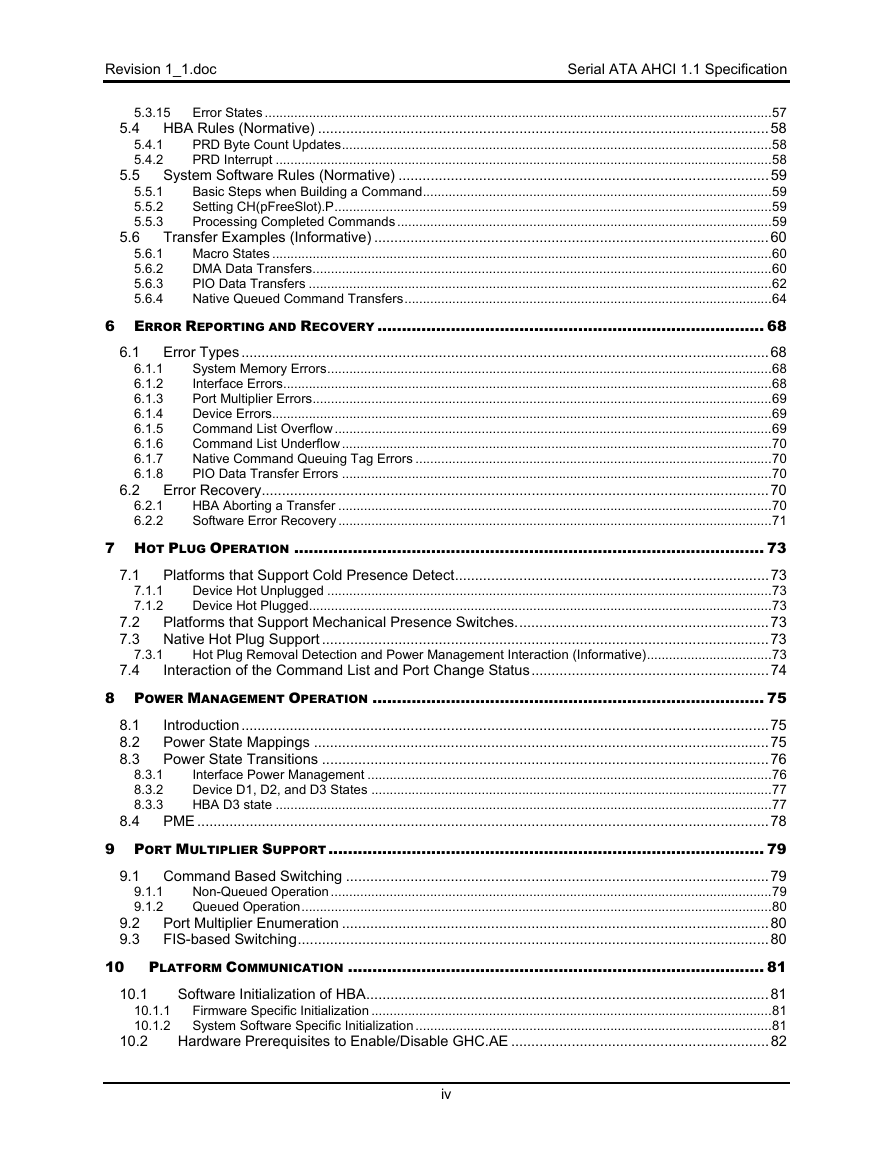
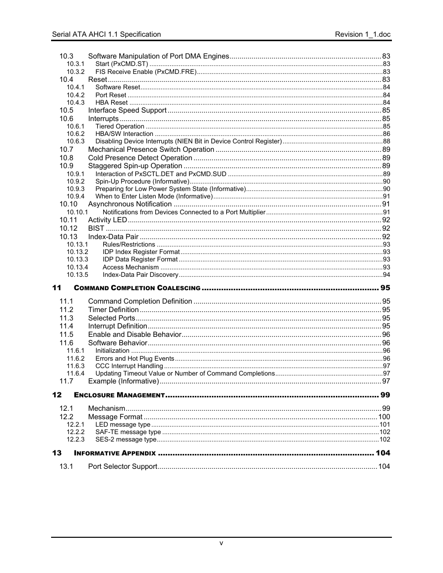
Table of Contents
1
INTRODUCTION ............................................................................................................. 1
1.1 Overview.........................................................................................................................................1
1.2 Scope..............................................................................................................................................1
1.3 Outside of Scope ............................................................................................................................1
1.4 Block Diagram ................................................................................................................................1
1.5 Conventions....................................................................................................................................3
1.6 Definitions .......................................................................................................................................4
command list ..........................................................................................................................................4
1.6.1
command slot.........................................................................................................................................4
1.6.2
cs............................................................................................................................................................4
1.6.3
D2H ........................................................................................................................................................4
1.6.4
device.....................................................................................................................................................4
1.6.5
FIS..........................................................................................................................................................4
1.6.6
H2D ........................................................................................................................................................4
1.6.7
HBA........................................................................................................................................................4
1.6.8
n/a ..........................................................................................................................................................4
1.6.9
port .........................................................................................................................................................4
1.6.10
1.6.11 PRD........................................................................................................................................................4
queue .....................................................................................................................................................4
1.6.12
1.6.13
register memory .....................................................................................................................................4
1.6.14
system memory......................................................................................................................................5
Theory of Operation........................................................................................................................5
1.7
1.8
Interaction with Legacy Software....................................................................................................5
1.9 References .....................................................................................................................................6
2 HBA CONFIGURATION REGISTERS................................................................................... 7
2.1 PCI Header.....................................................................................................................................7
Offset 00h: ID - Identifiers ......................................................................................................................7
2.1.1
Offset 04h: CMD - Command.................................................................................................................7
2.1.2
Offset 06h: STS - Device Status.............................................................................................................8
2.1.3
Offset 08h: RID - Revision ID .................................................................................................................8
2.1.4
Offset 09h: CC - Class Code..................................................................................................................8
2.1.5
Offset 0Ch: CLS – Cache Line Size .......................................................................................................8
2.1.6
Offset 0Dh: MLT – Master Latency Timer ..............................................................................................9
2.1.7
Offset 0Eh: HTYPE – Header Type........................................................................................................9
2.1.8
2.1.9
Offset 0Fh: BIST – Built In Self Test (Optional)......................................................................................9
2.1.10 Offset 10h – 20h: BARS – Other Base Addresses (Optional) ................................................................9
2.1.11 Offset 24h: ABAR – AHCI Base Address ...............................................................................................9
2.1.12 Offset 2Ch: SS - Sub System Identifiers ................................................................................................9
2.1.13 Offset 30h: EROM – Expansion ROM (Optional) ...................................................................................9
2.1.14 Offset 34h: CAP – Capabilities Pointer.................................................................................................10
2.1.15 Offset 3Ch: INTR - Interrupt Information ..............................................................................................10
2.1.16 Offset 3Eh: MGNT – Minimum Grant (Optional)...................................................................................10
2.1.17 Offset 3Fh: MLAT – Maximum Latency (Optional) ...............................................................................10
2.2 PCI Power Management Capabilities...........................................................................................10
Offset PMCAP: PID - PCI Power Management Capability ID...............................................................10
2.2.1
Offset PMCAP + 2h: PC – PCI Power Management Capabilities.........................................................10
2.2.2
2.2.3
Offset PMCAP + 4h: PMCS – PCI Power Management Control And Status........................................11
2.3 Message Signaled Interrupt Capability (Optional)........................................................................11
Offset MSICAP: MID – Message Signaled Interrupt Identifiers ............................................................11
2.3.1
Offset MSICAP + 2h: MC – Message Signaled Interrupt Message Control..........................................11
2.3.2
Offset MSICAP + 4h: MA – Message Signaled Interrupt Message Address ........................................12
2.3.3
2.3.4
Offset MSICAP + (8h or Ch): MD – Message Signaled Interrupt Message Data..................................12
2.3.5
Offset MSICAP + 8h: MUA – Message Signaled Interrupt Upper Address (Optional)..........................12
2.4 Serial ATA Capability (Optional)...................................................................................................12
2.4.1
Offset SATACAP: SATACR0 – Serial ATA Capability Register 0.........................................................12
Offset SATACAP + 4h: SATACR1 – Serial ATA Capability Register 1 ................................................12
2.4.2
ii
�
Serial ATA AHCI 1.1 Specification
Revision 1_1.doc
3.1.1
3.1.2
3.1.3
3.1.4
3.1.5
3.1.6
3.1.7
3.1.8
3.1.9
2.5 Other Capability Pointers..............................................................................................................13
3 HBA MEMORY REGISTERS ........................................................................................... 14
3.1 Generic Host Control ....................................................................................................................14
Offset 00h: CAP – HBA Capabilities.....................................................................................................14
Offset 04h: GHC – Global HBA Control................................................................................................16
Offset 08h: IS – Interrupt Status Register.............................................................................................17
Offset 0Ch: PI – Ports Implemented.....................................................................................................17
Offset 10h: VS – AHCI Version ............................................................................................................18
Offset 14h: CCC_CTL – Command Completion Coalescing Control....................................................18
Offset 18h: CCC_PORTS – Command Completion Coalescing Ports .................................................19
Offset 1Ch: EM_LOC – Enclosure Management Location ...................................................................19
Offset 20h: EM_CTL – Enclosure Management Control ......................................................................19
3.2 Vendor Specific Registers ............................................................................................................20
3.3 Port Registers (one set per port) ..................................................................................................20
Offset 100h: P0CLB – Port 0 Command List Base Address.................................................................20
3.3.1
Offset 104h: P0CLBU – Port 0 Command List Base Address Upper 32-bits........................................21
3.3.2
Offset 108h: P0FB – Port 0 FIS Base Address ....................................................................................21
3.3.3
Offset 10Ch: P0FBU – Port 0 FIS Base Address Upper 32-bits...........................................................21
3.3.4
Offset 110h: P0IS – Port 0 Interrupt Status ..........................................................................................21
3.3.5
Offset 114h: P0IE – Port 0 Interrupt Enable .........................................................................................22
3.3.6
Offset 118h: P0CMD – Port 0 Command and Status ...........................................................................24
3.3.7
Offset 120h: P0TFD – Port 0 Task File Data........................................................................................26
3.3.8
Offset 124h: P0SIG – Port 0 Signature ................................................................................................26
3.3.9
3.3.10 Offset 128h: P0SSTS – Port 0 Serial ATA Status (SCR0: SStatus).....................................................27
3.3.11 Offset 12Ch: P0SCTL – Port 0 Serial ATA Control (SCR2: SControl)..................................................27
3.3.12 Offset 130h: P0SERR – Port 0 Serial ATA Error (SCR1: SError).........................................................29
3.3.13 Offset 134h: P0SACT – Port 0 Serial ATA Active (SCR3: SActive)......................................................30
3.3.14 Offset 138h: P0CI – Port 0 Command Issue ........................................................................................30
3.3.15 Offset 13Ch: P0SNTF – SNotification ..................................................................................................31
3.3.16 Offset 140h: Reserved for FIS-based Switching ..................................................................................31
3.3.17 Offset 170h to 17Fh: P0VS – Vendor Specific .....................................................................................31
4 SYSTEM MEMORY STRUCTURES .................................................................................... 32
4.1 HBA Memory Space Usage..........................................................................................................32
4.2 Port Memory Usage......................................................................................................................33
Received FIS Structure ........................................................................................................................34
Command List Structure.......................................................................................................................35
Command Table...................................................................................................................................38
5 DATA TRANSFER OPERATION........................................................................................ 40
Introduction...................................................................................................................................40
5.1
5.2 HBA Controller State Machine (Normative)..................................................................................40
Variables ..............................................................................................................................................40
5.2.1
HBA Idle States....................................................................................................................................40
5.2.2
5.3 HBA Port State Machine (Normative)...........................................................................................42
Variables ..............................................................................................................................................42
5.3.1
Port Idle States.....................................................................................................................................43
5.3.2
Power Management States ..................................................................................................................47
5.3.3
Non-Data FIS Receive States ..............................................................................................................48
5.3.4
Command Transfer States ...................................................................................................................49
5.3.5
ATAPI Command Transfer States........................................................................................................50
5.3.6
D2H Register FIS Receive States ........................................................................................................51
5.3.7
5.3.8
PIO Setup Receive States....................................................................................................................52
Data Transmit States............................................................................................................................53
5.3.9
5.3.10 Data Receive States.............................................................................................................................54
5.3.11 DMA Setup Receive States..................................................................................................................55
5.3.12 Set Device Bits States..........................................................................................................................56
5.3.13 Unknown FIS Receive States...............................................................................................................57
5.3.14 BIST States ..........................................................................................................................................57
4.2.1
4.2.2
4.2.3
iii
�
Revision 1_1.doc
Serial ATA AHCI 1.1 Specification
5.6
6.1.1
6.1.2
6.1.3
6.1.4
6.1.5
6.1.6
6.1.7
6.1.8
6.2.1
6.2.2
5.3.15 Error States ..........................................................................................................................................57
5.4 HBA Rules (Normative) ................................................................................................................58
5.4.1
PRD Byte Count Updates.....................................................................................................................58
5.4.2
PRD Interrupt .......................................................................................................................................58
5.5 System Software Rules (Normative) ............................................................................................59
5.5.1
Basic Steps when Building a Command...............................................................................................59
Setting CH(pFreeSlot).P.......................................................................................................................59
5.5.2
Processing Completed Commands ......................................................................................................59
5.5.3
Transfer Examples (Informative) ..................................................................................................60
5.6.1
Macro States ........................................................................................................................................60
DMA Data Transfers.............................................................................................................................60
5.6.2
PIO Data Transfers ..............................................................................................................................62
5.6.3
5.6.4
Native Queued Command Transfers....................................................................................................64
6 ERROR REPORTING AND RECOVERY ............................................................................... 68
6.1 Error Types ...................................................................................................................................68
System Memory Errors.........................................................................................................................68
Interface Errors.....................................................................................................................................68
Port Multiplier Errors.............................................................................................................................69
Device Errors........................................................................................................................................69
Command List Overflow.......................................................................................................................69
Command List Underflow .....................................................................................................................70
Native Command Queuing Tag Errors .................................................................................................70
PIO Data Transfer Errors .....................................................................................................................70
6.2 Error Recovery..............................................................................................................................70
HBA Aborting a Transfer ......................................................................................................................70
Software Error Recovery ......................................................................................................................71
7 HOT PLUG OPERATION ................................................................................................ 73
7.1 Platforms that Support Cold Presence Detect..............................................................................73
Device Hot Unplugged .........................................................................................................................73
Device Hot Plugged..............................................................................................................................73
7.2 Platforms that Support Mechanical Presence Switches...............................................................73
7.3 Native Hot Plug Support ...............................................................................................................73
Hot Plug Removal Detection and Power Management Interaction (Informative)..................................73
7.4
Interaction of the Command List and Port Change Status...........................................................74
8 POWER MANAGEMENT OPERATION ................................................................................ 75
8.1
Introduction...................................................................................................................................75
8.2 Power State Mappings .................................................................................................................75
8.3 Power State Transitions ...............................................................................................................76
Interface Power Management ..............................................................................................................76
Device D1, D2, and D3 States .............................................................................................................77
HBA D3 state .......................................................................................................................................77
8.4 PME ..............................................................................................................................................78
9 PORT MULTIPLIER SUPPORT......................................................................................... 79
9.1 Command Based Switching .........................................................................................................79
Non-Queued Operation ........................................................................................................................79
Queued Operation................................................................................................................................80
9.2 Port Multiplier Enumeration ..........................................................................................................80
FIS-based Switching.....................................................................................................................80
9.3
10 PLATFORM COMMUNICATION ..................................................................................... 81
Software Initialization of HBA....................................................................................................81
Firmware Specific Initialization .............................................................................................................81
10.1.1
10.1.2 System Software Specific Initialization .................................................................................................81
Hardware Prerequisites to Enable/Disable GHC.AE ................................................................82
8.3.1
8.3.2
8.3.3
10.1
10.2
7.1.1
7.1.2
7.3.1
9.1.1
9.1.2
iv
�
Serial ATA AHCI 1.1 Specification
Revision 1_1.doc
10.5
10.6
10.7
10.8
10.9
10.3
10.4
Software Manipulation of Port DMA Engines............................................................................83
10.3.1 Start (PxCMD.ST) ................................................................................................................................83
10.3.2
FIS Receive Enable (PxCMD.FRE)......................................................................................................83
Reset.........................................................................................................................................83
10.4.1 Software Reset.....................................................................................................................................84
10.4.2 Port Reset ............................................................................................................................................84
10.4.3 HBA Reset ...........................................................................................................................................84
Interface Speed Support ...........................................................................................................85
Interrupts ...................................................................................................................................85
10.6.1
Tiered Operation ..................................................................................................................................85
10.6.2 HBA/SW Interaction .............................................................................................................................86
10.6.3 Disabling Device Interrupts (NIEN Bit in Device Control Register).......................................................88
Mechanical Presence Switch Operation ...................................................................................89
Cold Presence Detect Operation ..............................................................................................89
Staggered Spin-up Operation ...................................................................................................89
10.9.1
Interaction of PxSCTL.DET and PxCMD.SUD .....................................................................................89
10.9.2 Spin-Up Procedure (Informative)..........................................................................................................90
10.9.3 Preparing for Low Power System State (Informative)...........................................................................90
10.9.4 When to Enter Listen Mode (Informative).............................................................................................91
10.10 Asynchronous Notification ........................................................................................................91
Notifications from Devices Connected to a Port Multiplier................................................................91
10.10.1
10.11 Activity LED...............................................................................................................................92
10.12 BIST ..........................................................................................................................................92
10.13
Index-Data Pair .........................................................................................................................92
Rules/Restrictions ............................................................................................................................93
IDP Index Register Format...............................................................................................................93
IDP Data Register Format ................................................................................................................93
Access Mechanism ..........................................................................................................................93
Index-Data Pair Discovery................................................................................................................94
11 COMMAND COMPLETION COALESCING ......................................................................... 95
Command Completion Definition ..............................................................................................95
Timer Definition.........................................................................................................................95
Selected Ports...........................................................................................................................95
Interrupt Definition.....................................................................................................................95
Enable and Disable Behavior....................................................................................................96
Software Behavior.....................................................................................................................96
Initialization ..........................................................................................................................................96
11.6.1
11.6.2 Errors and Hot Plug Events..................................................................................................................96
11.6.3 CCC Interrupt Handling ........................................................................................................................97
11.6.4 Updating Timeout Value or Number of Command Completions...........................................................97
Example (Informative)...............................................................................................................97
12 ENCLOSURE MANAGEMENT........................................................................................ 99
Mechanism................................................................................................................................99
Message Format .....................................................................................................................100
12.2.1
LED message type.............................................................................................................................101
12.2.2 SAF-TE message type .......................................................................................................................102
12.2.3 SES-2 message type..........................................................................................................................102
INFORMATIVE APPENDIX ......................................................................................... 104
Port Selector Support..............................................................................................................104
10.13.1
10.13.2
10.13.3
10.13.4
10.13.5
11.1
11.2
11.3
11.4
11.5
11.6
13
13.1
11.7
12.1
12.2
v
�
Revision 1_1.doc
Serial ATA AHCI 1.1 Specification
Table of Figures
Figure 1: IA Based System Diagram ..............................................................................................................................2
Figure 2: Embedded System Diagram ...........................................................................................................................3
Figure 3: Example of HBA Silicon Supporting Both Legacy and AHCI Interfaces..........................................................6
Figure 4: HBA Memory Space Usage ..........................................................................................................................32
Figure 5: Port System Memory Structures ...................................................................................................................33
Figure 6: Received FIS Organization ...........................................................................................................................34
Figure 7: Command List Structure ...............................................................................................................................35
Figure 8: DW 0 – Description Information ....................................................................................................................36
Figure 9: DW 1 - Command Status ..............................................................................................................................36
Figure 10: DW 2 – Command Table Base Address .....................................................................................................36
Figure 11: DW 3 – Command Table Base Address Upper...........................................................................................36
Figure 12: DW 4-7 – Reserved.....................................................................................................................................37
Figure 13: Command Table .........................................................................................................................................38
Figure 14: DW 0 – Data Base Address ........................................................................................................................39
Figure 15: DW 1 – Data Base Address Upper .............................................................................................................39
Figure 16: DW 2 – Reserved........................................................................................................................................39
Figure 17: DW 3 – Description Information ..................................................................................................................39
Figure 18: Power State Hierarchy ................................................................................................................................75
Figure 19: Interrupt Tiers..............................................................................................................................................86
Figure 20: MSI vs. PCI IRQ Actions .............................................................................................................................87
Figure 21: Port/CCC and MSI Message Mapping, Example 1 .....................................................................................88
Figure 22: Port and MSI Message Mapping, Example 2 ..............................................................................................88
Figure 23: Enclosure Management Buffer Location ...................................................................................................100
vi
�
Serial ATA AHCI 1.1 Specification
Revision 1_1.doc
Introduction
1
1.1 Overview
This specification defines the functional behavior and software interface of the Advanced Host Controller
Interface, which is a hardware mechanism that allows software to communicate with Serial ATA devices.
AHCI is a PCI class device that acts as a data movement engine between system memory and Serial
ATA devices.
AHCI host devices (referred to as host bus adapters, or HBA) support from 1 to 32 ports. An HBA must
support ATA and ATAPI devices, and must support both the PIO and DMA protocols. An HBA may
optionally support a command list on each port for overhead reduction, and to support Serial ATA Native
Command Queuing via the FPDMA Queued Command protocol for each device of up to 32 entries. An
HBA may optionally support 64-bit addressing.
AHCI describes a system memory structure which contains a generic area for control and status, and a
table of entries describing a command list (an HBA which does not support a command list shall have a
depth of one for this table). Each command list entry contains information necessary to program an
SATA device, and a pointer to a descriptor table for transferring data between system memory and the
device.
1.2 Scope
AHCI encompasses a PCI device. It contains a PCI BAR (Base Address Register) to implement native
SATA features. AHCI specifies the following features:
•
•
•
•
•
•
Support for 32 ports
Elimination of Master / Slave Handling
Hot Plug
HW Assisted Native Command Queuing
Cold device presence detect
Activity LED generation
•
•
•
•
•
•
64-bit addressing
Large LBA support
Power Management
Staggered Spin-up
Serial ATA superset registers
Port Multiplier
1.3 Outside of Scope
AHCI does not contain information relevant to implementing the Transport, Link or Phy layers of Serial
ATA as this is wholly described in the Serial ATA 1.0a specification.
AHCI does not specify ATA legacy behavior, such as the legacy I/O ranges, or Bus Master IDE.
Allowances have been made in AHCI so that an HBA may implement these features for backward
compatibility with older operating systems (for example, the location of the memory BAR for AHCI is after
the BAR locations for both native IDE and bus master IDE).
1.4 Block Diagram
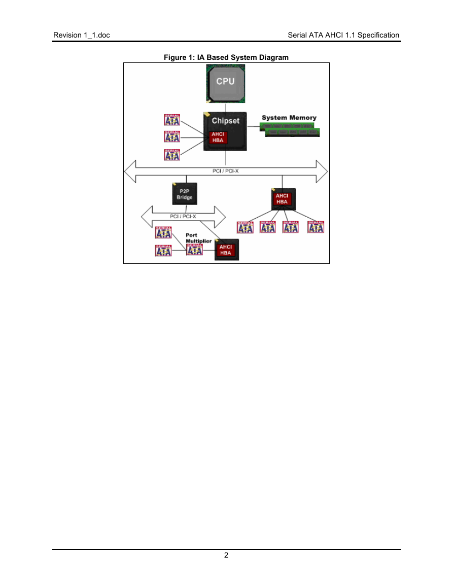
In Figure 1, several AHCI HBAs are attached in a typical computer system. One HBA is integrated in the
core chipset. Another sits off the first available PCI/PCI-X bus. (PCI is used as a reference name. The
bus can be any PCI-like bus, such as PCI-X, PCI-Express, HyperTransport, etc.) The intent is to be
compliant with the PCI base specification. Compliance with non-PCI specifications is dependant upon
those specifications being compliant/compatible with PCI.
A final HBA sits off a second PCI bus that exists behind a PCI-PCI bridge. This last HBA has one port
attached to a Port Multiplier
1
�
Revision 1_1.doc
Serial ATA AHCI 1.1 Specification
Figure 1: IA Based System Diagram
2
�




 2023年江西萍乡中考道德与法治真题及答案.doc
 2012年重庆南川中考生物真题及答案.doc
 2013年江西师范大学地理学综合及文艺理论基础考研真题.doc
 2020年四川甘孜小升初语文真题及答案I卷.doc
 2020年注册岩土工程师专业基础考试真题及答案.doc
 2023-2024学年福建省厦门市九年级上学期数学月考试题及答案.doc
 2021-2022学年辽宁省沈阳市大东区九年级上学期语文期末试题及答案.doc
 2022-2023学年北京东城区初三第一学期物理期末试卷及答案.doc
 2018上半年江西教师资格初中地理学科知识与教学能力真题及答案.doc
 2012年河北国家公务员申论考试真题及答案-省级.doc
 2020-2021学年江苏省扬州市江都区邵樊片九年级上学期数学第一次质量检测试题及答案.doc
 2022下半年黑龙江教师资格证中学综合素质真题及答案.doc