logo资料库

F1C800_Datasheet_V1.0.pdf

第1页 / 共52页
第2页 / 共52页
第3页 / 共52页
第4页 / 共52页
第5页 / 共52页
第6页 / 共52页
第7页 / 共52页
第8页 / 共52页
资料共52页,剩余部分请下载后查看
Revision History
Declaration
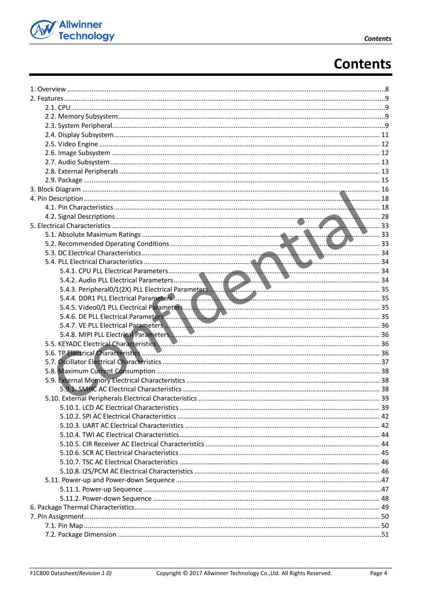
Contents
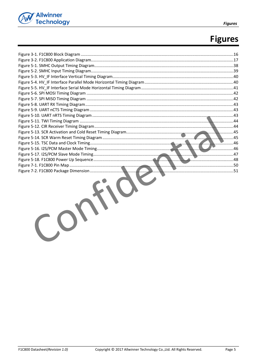
Figures
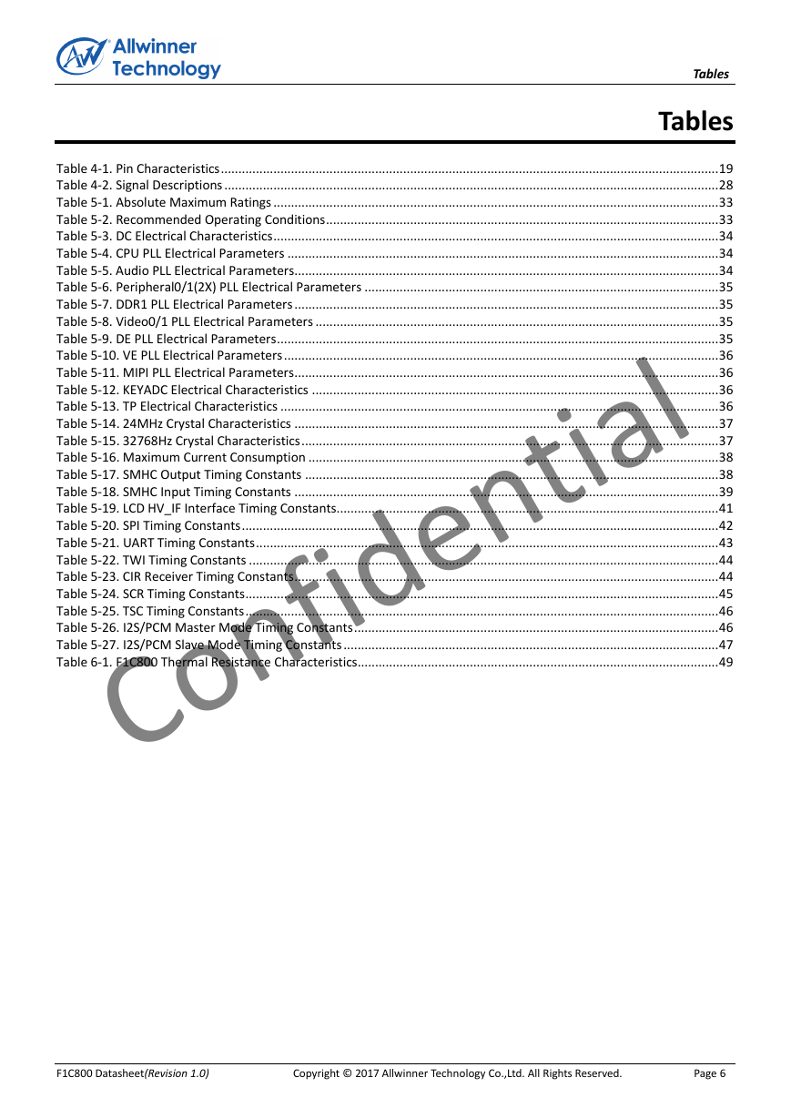
Tables
About This Documentation
1. Overview
2. Features
2.1. CPU
2.2. Memory Subsystem
Boot ROM
SDRAM
SMHC
2.3. System Peripheral
CCU
Timer
High Speed Timer
RTC
INTC
DMA
PWM
KEYADC
TP
Crypto Engine(CE)
Security ID
2.4. Display Subsystem
DE2.0
Display Output
2.5. Video Engine
Video Decoder
2.6. Image Subsystem
TVIN
2.7. Audio Subsystem
Audio Codec
I2S/PCM
2.8. External Peripherals
USB
TWI
SPI
UART
CIR Receiver
SCR
TSC
2.9. Package
3. Block Diagram
4. Pin Description
4.1. Pin Characteristics
4.2. Signal Descriptions
5. Electrical Characteristics
5.1. Absolute Maximum Ratings
5.2. Recommended Operating Conditions
5.3. DC Electrical Characteristics
5.4. PLL Electrical Characteristics
5.4.1. CPU PLL Electrical Parameters
5.4.2. Audio PLL Electrical Parameters
5.4.3. Peripheral0/1(2X) PLL Electrical Parameters
5.4.4. DDR1 PLL Electrical Parameters
5.4.5. Video0/1 PLL Electrical Parameters
5.4.6. DE PLL Electrical Parameters
5.4.7. VE PLL Electrical Parameters
5.4.8. MIPI PLL Electrical Parameters
5.5. KEYADC Electrical Characteristics
5.6. TP Electrical Characteristics
5.7. Oscillator Electrical Characteristics
5.8. Maximum Current Consumption
5.9. External Memory Electrical Characteristics
5.9.1. SMHC AC Electrical Characteristics
5.10. External Peripherals Electrical Characteristics
5.10.1. LCD AC Electrical Characteristics
5.10.2. SPI AC Electrical Characteristics
5.10.3. UART AC Electrical Characteristics
5.10.4. TWI AC Electrical Characteristics
5.10.5. CIR Receiver AC Electrical Characteristics
5.10.6. SCR AC Electrical Characteristics
5.10.7. TSC AC Electrical Characteristics
5.10.8. I2S/PCM AC Electrical Characteristics
5.11. Power-up and Power-down Sequence
5.11.1. Power-up Sequence
5.11.2. Power-down Sequence
6. Package Thermal Characteristics
7. Pin Assignment
7.1. Pin Map
7.2. Package Dimension
F1 C800 Datasheet HD Video Boombox Processor Revision 1.0 Mar. 14, 2017 Copyright © 2017 Allwinner Technology Co.,Ltd. All Rights Reserved. Confidential
Revision History Revision History Revision 1.0 Date Mar.14,2017 Description Initial Release Version. F1C800 Datasheet(Revision 1.0) Copyright © 2017 Allwinner Technology Co.,Ltd. All Rights Reserved. Page 2 Confidential
Declaration Declaration THIS DOCUMENTATION IS THE ORIGINAL WORK AND COPYRIGHTED PROPERTY OF ALLWINNER TECHNOLOGY (“ALLWINNER”). REPRODUCTION IN WHOLE OR IN PART MUST OBTAIN THE WRITTEN APPROVAL OF ALLWINNER AND GIVE CLEAR ACKNOWLEDGEMENT TO THE COPYRIGHT OWNER. THE INFORMATION FURNISHED BY ALLWINNER IS BELIEVED TO BE ACCURATE AND RELIABLE. ALLWINNER RESERVES THE RIGHT TO MAKE CHANGES IN CIRCUIT DESIGN AND/OR SPECIFICATIONS AT ANY TIME WITHOUT NOTICE. ALLWINNER DOES NOT ASSUME ANY RESPONSIBILITY AND LIABILITY FOR ITS USE. NOR FOR ANY INFRINGEMENTS OF PATENTS OR OTHER RIGHTS OF THE THIRD PARTIES WHICH MAY RESULT FROM ITS USE. NO LICENSE IS GRANTED BY IMPLICATION OR OTHERWISE UNDER ANY PATENT OR PATENT RIGHTS OF ALLWINNER. THIS DATASHEET NEITHER STATES NOR IMPLIES WARRANTY OF ANY KIND, INCLUDING FITNESS FOR ANY PARTICULAR APPLICATION. THIRD PARTY LICENCES MAY BE REQUIRED TO IMPLEMENT THE SOLUTION/PRODUCT. CUSTOMERS SHALL BE SOLELY RESPONSIBLE TO OBTAIN ALL APPROPRIATELY REQUIRED THIRD PARTY LICENCES. ALLWINNER SHALL NOT BE LIABLE FOR ANY LICENCE FEE OR ROYALTY DUE IN RESPECT OF ANY REQUIRED THIRD PARTY LICENCE. ALLWINNER SHALL HAVE NO WARRANTY, INDEMNITY OR OTHER OBLIGATIONS WITH RESPECT TO MATTERS COVERED UNDER ANY REQUIRED THIRD PARTY LICENCE. F1C800 Datasheet(Revision 1.0) Copyright © 2017 Allwinner Technology Co.,Ltd. All Rights Reserved. Page 3 Confidential
Contents Contents 1. Overview ..........................................................................................................................................................................8 2. Features ............................................................................................................................................................................9 2.1. CPU ........................................................................................................................................................................9 2.2. Memory Subsystem...............................................................................................................................................9 2.3. System Peripheral ..................................................................................................................................................9 2.4. Display Subsystem .............................................................................................................................................. 11 2.5. Video Engine ...................................................................................................................................................... 12 2.6. Image Subsystem ............................................................................................................................................... 12 2.7. Audio Subsystem ................................................................................................................................................ 13 2.8. External Peripherals ........................................................................................................................................... 13 2.9. Package .............................................................................................................................................................. 15 3. Block Diagram ............................................................................................................................................................... 16 4. Pin Description .............................................................................................................................................................. 18 4.1. Pin Characteristics .............................................................................................................................................. 18 4.2. Signal Descriptions ............................................................................................................................................. 28 5. Electrical Characteristics ............................................................................................................................................... 33 5.1. Absolute Maximum Ratings ............................................................................................................................... 33 5.2. Recommended Operating Conditions ................................................................................................................ 33 5.3. DC Electrical Characteristics ............................................................................................................................... 34 5.4. PLL Electrical Characteristics .............................................................................................................................. 34 5.4.1. CPU PLL Electrical Parameters ................................................................................................................. 34 5.4.2. Audio PLL Electrical Parameters .............................................................................................................. 34 5.4.3. Peripheral0/1(2X) PLL Electrical Parameters ........................................................................................... 35 5.4.4. DDR1 PLL Electrical Parameters .............................................................................................................. 35 5.4.5. Video0/1 PLL Electrical Parameters ......................................................................................................... 35 5.4.6. DE PLL Electrical Parameters ................................................................................................................... 35 5.4.7. VE PLL Electrical Parameters ................................................................................................................... 36 5.4.8. MIPI PLL Electrical Parameters ................................................................................................................ 36 5.5. KEYADC Electrical Characteristics ....................................................................................................................... 36 5.6. TP Electrical Characteristics ............................................................................................................................... 36 5.7. Oscillator Electrical Characteristics ..................................................................................................................... 37 5.8. Maximum Current Consumption ....................................................................................................................... 38 5.9. External Memory Electrical Characteristics ....................................................................................................... 38 5.9.1. SMHC AC Electrical Characteristics ......................................................................................................... 38 5.10. External Peripherals Electrical Characteristics ................................................................................................. 39 5.10.1. LCD AC Electrical Characteristics ........................................................................................................... 39 5.10.2. SPI AC Electrical Characteristics ............................................................................................................ 42 5.10.3. UART AC Electrical Characteristics ........................................................................................................ 42 5.10.4. TWI AC Electrical Characteristics ........................................................................................................... 44 5.10.5. CIR Receiver AC Electrical Characteristics ............................................................................................. 44 5.10.6. SCR AC Electrical Characteristics ........................................................................................................... 45 5.10.7. TSC AC Electrical Characteristics ........................................................................................................... 46 5.10.8. I2S/PCM AC Electrical Characteristics ................................................................................................... 46 5.11. Power-up and Power-down Sequence .............................................................................................................. 47 5.11.1. Power-up Sequence ............................................................................................................................... 47 5.11.2. Power-down Sequence ......................................................................................................................... 48 6. Package Thermal Characteristics ................................................................................................................................... 49 7. Pin Assignment .............................................................................................................................................................. 50 7.1. Pin Map .............................................................................................................................................................. 50 7.2. Package Dimension .............................................................................................................................................51 F1C800 Datasheet(Revision 1.0) Copyright © 2017 Allwinner Technology Co.,Ltd. All Rights Reserved. Page 4 Confidential
Figures Figures Figure 3-1. F1C800 Block Diagram ...................................................................................................................................... 16 Figure 3-2. F1C800 Application Diagram............................................................................................................................. 17 Figure 5-1. SMHC Output Timing Diagram .......................................................................................................................... 38 Figure 5-2. SMHC Input Timing Diagram ............................................................................................................................. 39 Figure 5-3. HV_IF Interface Vertical Timing Diagram .......................................................................................................... 40 Figure 5-4. HV_IF Interface Parallel Mode Horizontal Timing Diagram .............................................................................. 40 Figure 5-5. HV_IF Interface Serial Mode Horizontal Timing Diagram ................................................................................. 41 Figure 5-6. SPI MOSI Timing Diagram ................................................................................................................................. 42 Figure 5-7. SPI MISO Timing Diagram ................................................................................................................................. 42 Figure 5-8. UART RX Timing Diagram .................................................................................................................................. 43 Figure 5-9. UART nCTS Timing Diagram .............................................................................................................................. 43 Figure 5-10. UART nRTS Timing Diagram ............................................................................................................................ 43 Figure 5-11. TWI Timing Diagram ....................................................................................................................................... 44 Figure 5-12. CIR Receiver Timing Diagram .......................................................................................................................... 44 Figure 5-13. SCR Activation and Cold Reset Timing Diagram .............................................................................................. 45 Figure 5-14. SCR Warm Reset Timing Diagram ................................................................................................................... 45 Figure 5-15. TSC Data and Clock Timing .............................................................................................................................. 46 Figure 5-16. I2S/PCM Master Mode Timing ........................................................................................................................ 46 Figure 5-17. I2S/PCM Slave Mode Timing ........................................................................................................................... 47 Figure 5-18. F1C800 Power Up Sequence ........................................................................................................................... 48 Figure 7-1. F1C800 Pin Map ................................................................................................................................................ 50 Figure 7-2. F1C800 Package Dimension .............................................................................................................................. 51 F1C800 Datasheet(Revision 1.0) Copyright © 2017 Allwinner Technology Co.,Ltd. All Rights Reserved. Page 5 Confidential
Tables Tables Table 4-1. Pin Characteristics .............................................................................................................................................. 19 Table 4-2. Signal Descriptions ............................................................................................................................................. 28 Table 5-1. Absolute Maximum Ratings ............................................................................................................................... 33 Table 5-2. Recommended Operating Conditions ................................................................................................................ 33 Table 5-3. DC Electrical Characteristics ............................................................................................................................... 34 Table 5-4. CPU PLL Electrical Parameters ........................................................................................................................... 34 Table 5-5. Audio PLL Electrical Parameters ......................................................................................................................... 34 Table 5-6. Peripheral0/1(2X) PLL Electrical Parameters ..................................................................................................... 35 Table 5-7. DDR1 PLL Electrical Parameters ......................................................................................................................... 35 Table 5-8. Video0/1 PLL Electrical Parameters ................................................................................................................... 35 Table 5-9. DE PLL Electrical Parameters .............................................................................................................................. 35 Table 5-10. VE PLL Electrical Parameters ............................................................................................................................ 36 Table 5-11. MIPI PLL Electrical Parameters ......................................................................................................................... 36 Table 5-12. KEYADC Electrical Characteristics .................................................................................................................... 36 Table 5-13. TP Electrical Characteristics ............................................................................................................................. 36 Table 5-14. 24MHz Crystal Characteristics ......................................................................................................................... 37 Table 5-15. 32768Hz Crystal Characteristics ....................................................................................................................... 37 Table 5-16. Maximum Current Consumption ..................................................................................................................... 38 Table 5-17. SMHC Output Timing Constants ...................................................................................................................... 38 Table 5-18. SMHC Input Timing Constants ......................................................................................................................... 39 Table 5-19. LCD HV_IF Interface Timing Constants............................................................................................................. 41 Table 5-20. SPI Timing Constants ........................................................................................................................................ 42 Table 5-21. UART Timing Constants .................................................................................................................................... 43 Table 5-22. TWI Timing Constants ...................................................................................................................................... 44 Table 5-23. CIR Receiver Timing Constants ......................................................................................................................... 44 Table 5-24. SCR Timing Constants ....................................................................................................................................... 45 Table 5-25. TSC Timing Constants ....................................................................................................................................... 46 Table 5-26. I2S/PCM Master Mode Timing Constants ........................................................................................................ 46 Table 5-27. I2S/PCM Slave Mode Timing Constants ........................................................................................................... 47 Table 6-1. F1C800 Thermal Resistance Characteristics....................................................................................................... 49 F1C800 Datasheet(Revision 1.0) Copyright © 2017 Allwinner Technology Co.,Ltd. All Rights Reserved. Page 6 Confidential
About This Documentation About This Documentation The documentation describes features of each module, pin/signal characteristics, current consumption, PLL electrical characteristics, the interface timing, thermal and package of F1C800 processor. The documentation is intended to provide guidance to the hardware designers for electronics or sales personnel for electronic components. This documentation assumes that the reader has a background in electronic components. For details about register descriptions of each module, see the F1C800 User Manual. F1C800 Datasheet(Revision 1.0) Copyright © 2017 Allwinner Technology Co.,Ltd. All Rights Reserved. Page 7 Confidential
Overview 1. Overview The F1C800 processor represents Allwinner’s latest achievement in HD Video Boombox products. The processor adopts the latest H.265 video decoder, advanced audio system, low-power technology and high integration architecture design. These features help F1C800 keep the leading user experience in HD video playback, image quality and total performance. Integrated 4-lane MIPI DSI display output interface is up to 1080p@60fps. In order to reduce the BOM cost, the F1C800 integrates an internal DDR2 memory. A number of interfaces, such as RGB LCD, LVDS, TVIN, TVOUT, USB, I2S/PCM, UART, SPI, provide the flexible connecting solutions. F1C800 Datasheet(Revision 1.0) Copyright © 2017 Allwinner Technology Co.,Ltd. All Rights Reserved. Page 8 Confidential
分享到:
收藏