Front Cover
Inside Front Cover
Title Page
Dedication Page
Copyright Page
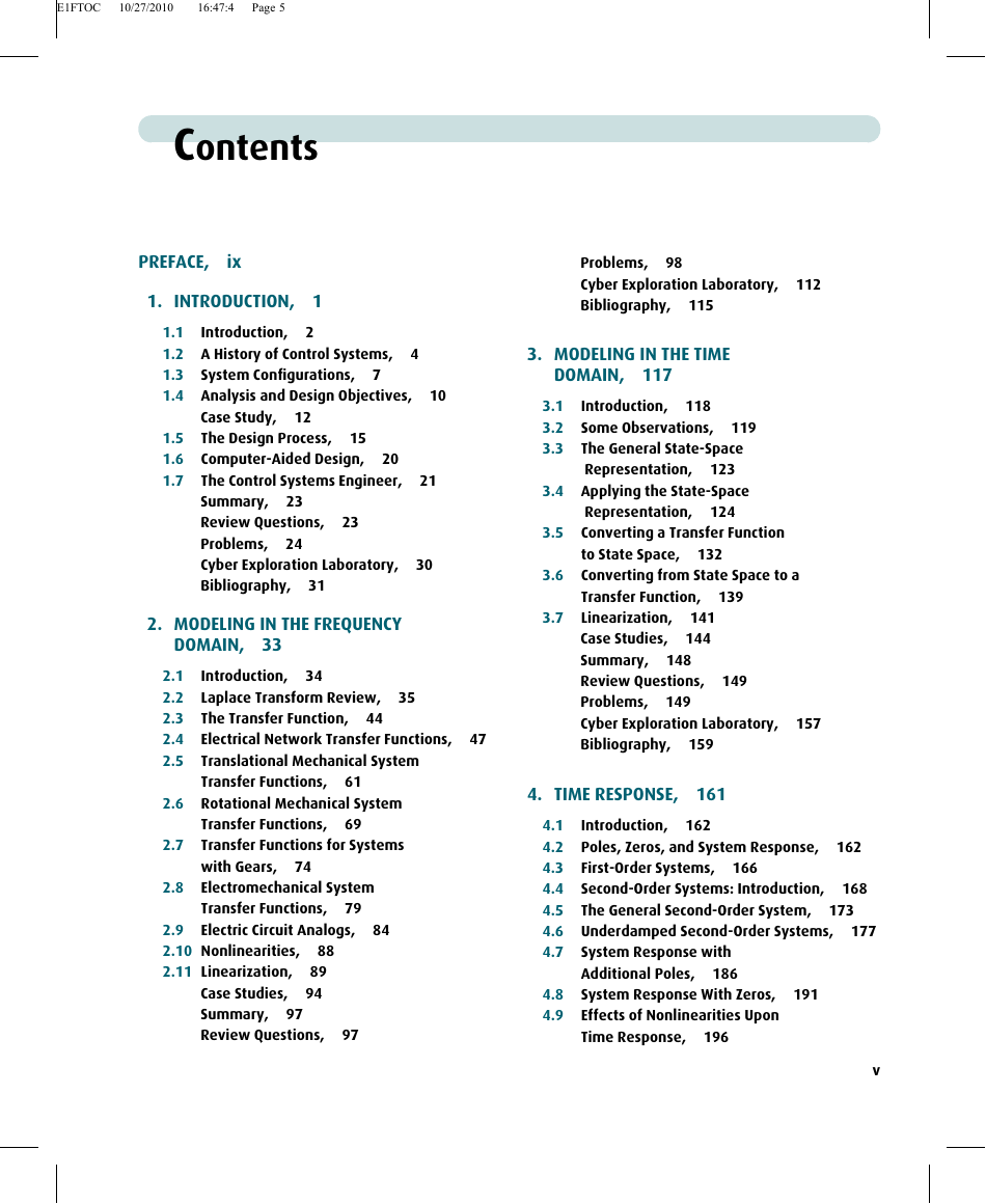
CONTENTS
Preface
Icons Identifying Major Topics
1. INTRODUCTION
1.1 Introduction
Control System Definition
Advantages of Control Systems
1.2 A History of Control Systems
Liquid-Level Control
Steam Pressure and Temperature Controls
Speed Control
Stability, Stabilization, and Steering
Twentieth-Century Developments
Contemporary Applications
1.3 System Configurations
Open-Loop Systems
Closed-Loop (Feedback Control) Systems
Computer-Controlled Systems
1.4 Analysis and Design Objectives
Transient Response
Steady-State Response
Stability
Other Considerations
Case Study
1.5 The Design Process
Step 1: Transform Requirements Into a Physical System
Step 2: Draw a Functional Block Diagram
Step 3: Create a Schematic
Step 4: Develop a Mathematical Model (Block Diagram)
Step 5: Reduce the Block Diagram
Step 6: Analyze and Design
1.6 Computer-Aided Design
MATLAB
LabVIEW
1.7 The Control Systems Engineer
Summary
Review Questions
Problems
Cyber Exploration Laboratory
Bibliography
2. MODELING IN THE FREQUENCY DOMAIN
2.1 Introduction
2.2 Laplace Transform Review
Partial-Fraction Expansion
2.3 The Transfer Function
2.4 Electrical Network Transfer Functions
Simple Circuits via Mesh Analysis
Simple Circuits via Nodal Analysis
Simple Circuits via Voltage Division
Complex Circuits via Mesh Analysis
Complex Circuits via Nodal Analysis
A Problem-Solving Technique
Operational Amplifiers
Inverting Operational Amplifier
Noninverting Operational Amplifier
2.5 Translational Mechanical System Transfer Functions
2.6 Rotational Mechanical System Transfer Functions
2.7 Transfer Functions for Systems with Gears
2.8 Electromechanical System Transfer Functions
2.9 Electric Circuit Analogs
Series Analog
Parallel Analog
2.10 Nonlinearities
2.11 Linearization
Case Studies
Summary
Review Questions
Problems
Cyber Exploration Laboratory
Bibliography
3. MODELING IN THE TIME DOMAIN
3.1 Introduction
3.2 Some Observations
3.3 The General State-Space Representation
3.4 Applying the State-Space Representation
Minimum Number of State Variables
3.5 Converting a Transfer Function to State Space
3.6 Converting from State Space to a Transfer Function
3.7 Linearization
Case Studies
Summary
Review Questions
Problems
Cyber Exploration Laboratory
Bibliography
4. TIME RESPONSE
4.1 Introduction
4.2 Poles, Zeros, and System Response
Poles of a Transfer Function
Zeros of a Transfer Function
Poles and Zeros of a First-Order System: An Example
4.3 First-Order Systems
Time Constant
Rise Time, Tr
Settling Time, Ts
First-Order Transfer Functions via Testing
4.4 Second-Order Systems: Introduction
Overdamped Response, Figure 4.7(b)
Underdamped Response, Figure 4.7 (c)
Undamped Response, Figure 4.7(d)
Critically Damped Response, Figure 4.7 (e)
4.5 The General Second-Order System
Natural Frequency, ωn
Damping Ratio, ζ
4.6 Underdamped Second-Order Systems
Evaluation of Tp
Evaluation of Ts
Evaluation of Tr
Second-Order Transfer Functions via Testing
4.7 System Response with Additional Poles
4.8 System Response With Zeros
4.9 Effects of Nonlinearities Upon Time Response
4.10 Laplace Transform Solution of State Equations
Eigenvalues and Transfer Function Poles
4.11 Time Domain Solution of State Equations
Case Studies
Summary
Review Questions
Problems
Cyber Exploration Laboratory
Bibliography
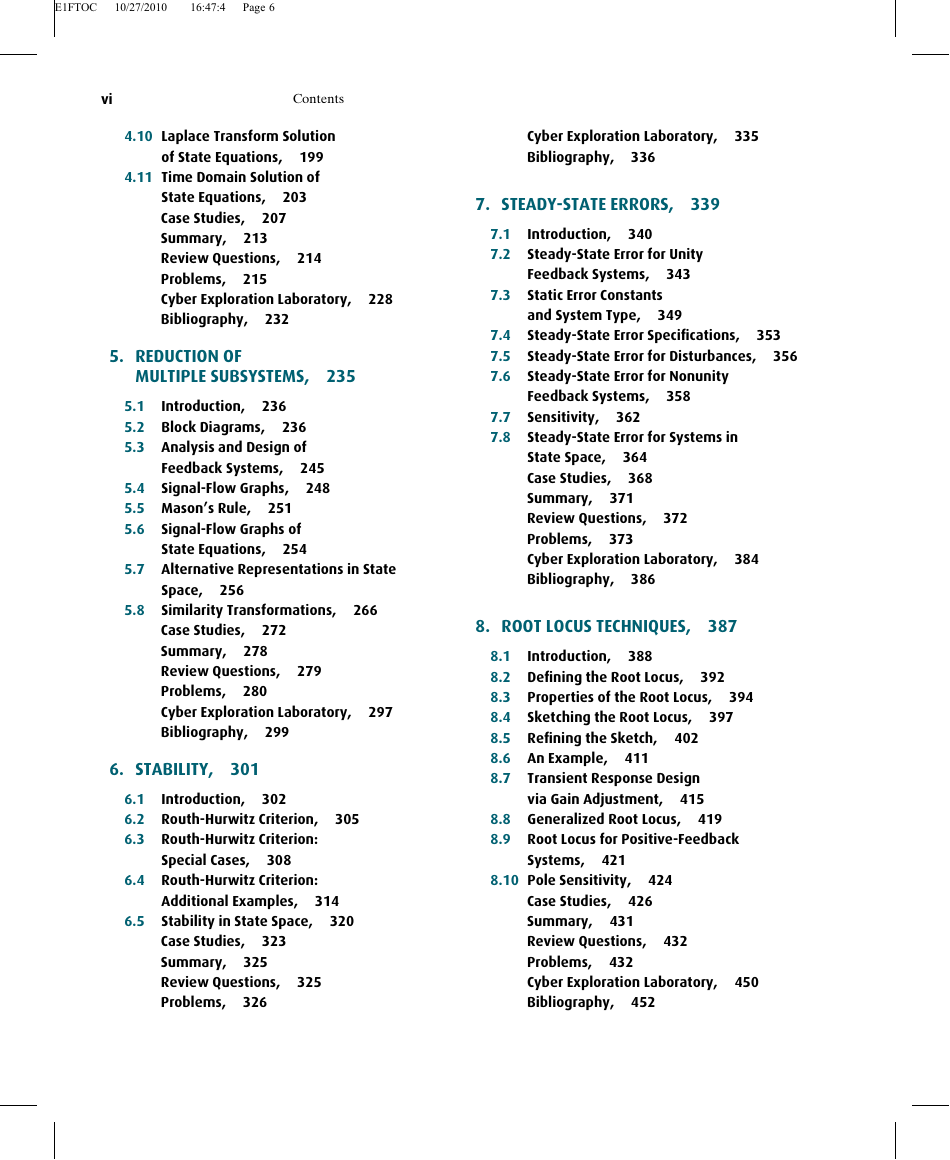
5. REDUCTION OF MULTIPLE SUBSYSTEMS
5.1 Introduction
5.2 Block Diagrams
Cascade Form
Parallel Form
Feedback Form
Moving Blocks to Create Familiar Forms
5.3 Analysis and Design of Feedback Systems
5.4 Signal-Flow Graphs
5.5 Mason’s Rule
Definitions
Mason’s Rule
5.6 Signal-Flow Graphs of State Equations
5.7 Alternative Representations in State Space
Cascade Form
Parallel Form
Controller Canonical Form
Observer Canonical Form
5.8 Similarity Transformations
Diagonalizing a System Matrix
Definitions
Case Studies
Summary
Review Questions
Problems
Cyber Exploration Laboratory
Bibliography
6. STABILITY
6.1 Introduction
6.2 Routh-Hurwitz Criterion
Generating a Basic Routh Table
Interpreting the Basic Routh Table
6.3 Routh-Hurwitz Criterion: Special Cases
Zero Only in the First Column
Entire Row is Zero
6.4 Routh-Hurwitz Criterion: Additional Examples
6.5 Stability in State Space
Case Studies
Summary
Review Questions
Problems
Cyber Exploration Laboratory
Bibliography
7. STEADY-STATE ERRORS
7.1 Introduction
Definition and Test Inputs
Application to Stable Systems
Evaluating Steady-State Errors
Sources of Steady-State Error
7.2 Steady-State Error for Unity Feedback Systems
Steady-State Error in Terms of T(s)
Steady-State Error in Terms of G(s)
7.3 Static Error Constants and System Type
System Type
7.4 Steady-State Error Specifications
7.5 Steady-State Error for Disturbances
7.6 Steady-State Error for Nonunity Feedback Systems
7.7 Sensitivity
7.8 Steady-State Error for Systems in State Space
Analysis via Final Value Theorem
Analysis via Input Substitution
Case Studies
Summary
Review Questions
Problems
Cyber Exploration Laboratory
Bibliography
8. ROOT LOCUS TECHNIQUES
8.1 Introduction
The Control System Problem
Vector Representation of Complex Numbers
8.2 Defining the Root Locus
8.3 Properties of the Root Locus
8.4 Sketching the Root Locus
8.5 Refining the Sketch
The jω-Axis Crossings
Angles of Departure and Arrival
Plotting and Calibrating the Root Locus
8.6 An Example
Basic Rules for Sketching the Root Locus
Additional Rules for Refining the Sketch
8.7 Transient Response Design via Gain Adjustment
8.8 Generalized Root Locus
8.9 Root Locus for Positive-Feedback Systems
8.10 Pole Sensitivity
Case Studies
Summary
Review Questions
Problems
Cyber Exploration Laboratory
Bibliography
9. DESIGN VIA ROOT LOCUS
9.1 Introduction
Improving Transient Response
Improving Steady-State Error
Configurations
Compensators
9.2 Improving Steady-State Error via Cascade Compensation
Ideal Integral Compensation (PI)
Lag Compensation
9.3 Improving Transient Response via Cascade Compensation
Ideal Derivative Compensation (PD)
Lead Compensation
9.4 Improving Steady-State Error and Transient Response
PID Controller Design
Lag-Lead Compensator Design
Notch Filter
9.5 Feedback Compensation
Approach 1
Approach 2
9.6 Physical Realization of Compensation
Active-Circuit Realization
Passive-Circuit Realization
Case Studies
Summary
Review Questions
Problems
Cyber Exploration Laboratory
Bibliography
10. FREQUENCY RESPONSE TECHNIQUES
10.1 Introduction
The Concept of Frequency Response
Analytical Expressions for Frequency Response
Plotting Frequency Response
10.2 Asymptotic Approximations: Bode Plots
Bode Plots for G(s) = (s + a)
Bode Plots for G(s) =1/(s+a)
Bode Plots for G(s)=s
Bode Plots for G(s)=1/s
Bode Plots for G(s)= s² + 2ζωnS + ωn²
Corrections to Second-Order Bode Plots
Bode Plots for G(s) = 1/(s²+ + 2ζωnS + ωn²)
Bode Plots for Ratio of First- and Second-Order Factors
10.3 Introduction to the Nyquist Criterion
Derivation of the Nyquist Criterion
Applying the Nyquist Criterion to Determine Stability
10.4 Sketching the Nyquist Diagram
10.5 Stability via the Nyquist Diagram
Stability via Mapping Only the Positive jω-Axis
10.6 Gain Margin and Phase Margin via the Nyquist Diagram
10.7 Stability, Gain Margin, and Phase Margin via Bode Plots
Determining Stability
Evaluating Gain and Phase Margins
10.8 Relation Between Closed-Loop Transient and Closed-Loop Frequency Responses
Damping Ratio and Closed-Loop Frequency Response
Response Speed and Closed-Loop Frequency Response
10.9 Relation Between Closed-and Open-Loop Frequency Responses
Constant M Circles and Constant N Circles
Nichols Charts
10.10 Relation Between Closed-Loop Transient and Open-Loop Frequency Responses
Damping Ratio From M Circles
Damping Ratio from Phase Margin
Response Speed from Open-Loop Frequency Response
10.11 Steady-State Error Characteristics from Frequency Response
Position Constant
Velocity Constant
Acceleration Constant
10.12 Systems with Time Delay
Modeling Time Delay
10.13 Obtaining Transfer Functions Experimentally
Case Study
Summary
Review Questions
Problems
Cyber Exploration Laboratory
Bibliography
11. DESIGN VIA FREQUENCY RESPONSE
11.1 Introduction
11.2 Transient Response via Gain Adjustment
Design Procedure
11.3 Lag Compensation
Visualizing Lag Compensation
Design Procedure
11.4 Lead Compensation
Visualizing Lead Compensation
Lead Compensator Frequency Response
Design Procedure
11.5 Lag-Lead Compensation
Design Procedure
Case Studies
Summary
Review Questions
Problems
Cyber Exploration Laboratory
Bibliography
12. DESIGN VIA STATE SPACE
12.1 Introduction
12.2 Controller Design
Topology for Pole Placement
Pole Placement for Plants in Phase-Variable Form
12.3 Controllability
Controllability by Inspection
The Controllability Matrix
12.4 Alternative Approaches to Controller Design
12.5 Observer Design
12.6 Observability
Observability by Inspection
The Observability Matrix
12.7 Alternative Approaches to Observer Design
12.8 Steady-State Error Design Via Integral Control
Case Study
Summary
Review Questions
Problems
Cyber Exploration Laboratory
Bibliography
13. DIGITAL CONTROL SYSTEMS
13.1 Introduction
Advantages of Digital Computers
Digital-to-Analog Conversion
Analog-to-Digital Conversion
13.2 Modeling the Digital Computer
Modeling the Sampler
Modeling the Zero-Order Hold
13.3 The z-Transform
The Inverse z-Transform
13.4 Transfer Functions
Derivation of the Pulse Transfer Function
13.5 Block Diagram Reduction
13.6 Stability
Digital System Stability via the z-Plane
Bilinear Transformations
Digital System Stability via the s-Plane
13.7 Steady-State Errors
Unit Step Input
Unit Ramp Input
Unit Parabolic Input
Summary of Steady-State Errors
13.8 Transient Response on the z-Plane
13.9 Gain Design on the z-Plane
13.10 Cascade Compensation via the s-Plane
Cascade Compensation
13.11 Implementing the Digital Compensator
Case Studies
Summary
Review Questions
Problems
Cyber Exploration Laboratory
Bibliography
APPENDICES
A: List of Symbols
B: MATLAB Tutorial
B.1 Introduction
B.2 MATLAB Examples
B.3 Command Summary
Bibliography
C: MATLAB’s Simulink Tutorial
C.1 Introduction
C.2 Using Simulink
C.3 Examples
Summary
Bibliography
D: LabVIEW™¹ Tutorial
D.1 Introduction
D.2 Control Systems Analysis, Design, and Simulation
D.3 Using LabVIEW
D.4 Analysis and Design Examples
D.5 Simulation Examples
Summary
Bibliography
Glossary
Answers to Selected Problems
Credits (Figures & Photos)
INDEX
Key Equations
Solutions to Skill-Assessment Exercises



 2023年江西萍乡中考道德与法治真题及答案.doc
 2012年重庆南川中考生物真题及答案.doc
 2013年江西师范大学地理学综合及文艺理论基础考研真题.doc
 2020年四川甘孜小升初语文真题及答案I卷.doc
 2020年注册岩土工程师专业基础考试真题及答案.doc
 2023-2024学年福建省厦门市九年级上学期数学月考试题及答案.doc
 2021-2022学年辽宁省沈阳市大东区九年级上学期语文期末试题及答案.doc
 2022-2023学年北京东城区初三第一学期物理期末试卷及答案.doc
 2018上半年江西教师资格初中地理学科知识与教学能力真题及答案.doc
 2012年河北国家公务员申论考试真题及答案-省级.doc
 2020-2021学年江苏省扬州市江都区邵樊片九年级上学期数学第一次质量检测试题及答案.doc
 2022下半年黑龙江教师资格证中学综合素质真题及答案.doc