IEEE TRANSACTIONS ON INDUSTRY APPLICATIONS, VOL. 39, NO. 4, JULY/AUGUST 2003
1031
Sensorless Drive of Surface-Mounted
Permanent-Magnet Motor by High-Frequency
Signal Injection Based on Magnetic Saliency
Ji-Hoon Jang, Student Member, IEEE, Seung-Ki Sul, Fellow, IEEE, Jung-Ik Ha, Member, IEEE,
Kozo Ide, Member, IEEE, and Mitsujiro Sawamura
Abstract—This paper presents a new sensorless control scheme
of a surface-mounted permanent-magnet (SMPM) motor using
high-frequency voltage signal
injection method based on the
high-frequency impedance difference. In the SMPM motor, due
to the flux of the permanent magnet, the stator core around the
-axis winding is saturated. This makes the magnetic saliency in
the motor. This magnetic saliency has the information about the
rotor position. The high-frequency voltage signal is injected into
the motor in order to detect the magnetic saliency and estimate
the rotor position. In this paper, the relationship between the
high-frequency voltages and high-frequency currents is developed
using the voltage equations at the high frequency, and the high-fre-
quency impedance characteristics are analyzed experimentally
under various conditions. The proposed sensorless control scheme
makes it possible to drive the SMPM motor in the low-speed
region including zero speed, even under heavy load conditions.
The experimental results verify the performance of the proposed
sensorless algorithm.
Index Terms—High-frequency signal injection, sensorless drive,
surface-mounted permanent-magnet (SMPM) motor.
I. INTRODUCTION
R ECENTLY, with the advent of high-performance perma-
nent magnets with high coercivity and high residual flux,
it has been possible for the permanent-magnet (PM) motors to
be superior to general-purpose induction motors in power den-
sity, torque-to-inertia ratio, and efficiency. Therefore, the PM
motors are of more and more interest in many industrial appli-
cations as substitutes for induction motors. Besides the afore-
mentioned advantages, the vector control of PM motors is much
simpler than that of induction motors because there is no need
to consider the slip frequency as in induction motor drive. How-
ever, PM motor drives require position sensors or rotational
transducers to perform the vector control correctly because the
rotor flux is obtained from permanent magnets. These position
Paper IPCSD 03–023, presented at the 2002 IEEE Applied Power Electronics
Conference and Exposition, Dallas, TX, March 10–14, and approved for publi-
cation in the IEEE TRANSACTIONS ON INDUSTRY APPLICATIONS by the Industrial
Drives Committee of the IEEE Industry Applications Society. Manuscript sub-
mitted for review June 1, 2002 and released for publication April 10, 2003.
J.-H. Jang and S.-K. Sul are with the School of Electrical Engineering and
Computer Science, Seoul National University, Seoul 151-744, Korea (e-mail:
bluemat@eepel.snu.ac.kr; sulsk@plaza.snu.ac.kr).
J.-I. Ha is with the Mechatronics Center, Samsung Electronics Company,
Suwon 442-742, Korea (e-mail: haji@ieee.org).
K. Ide and M. Sawamura are with the Mechatronics R&D Department, Cor-
porate R&D Center, Yaskawa Electric Company, Kitakyushu 803-8530, Japan
(e-mail: kozo@yaskawa.co.jp).
Digital Object Identifier 10.1109/TIA.2003.813734
sensors or rotational transducers not only increase cost, main-
tenance, and complexity, but also impair robustness and reli-
ability of the drive system. Therefore, many researchers have
been studying the sensorless drive of the PM motor in view of
the robustness, reliability, cost, and so on [1].
Conventional sensorless control schemes of the PM motor
can be classified into two types. The one is based on the back
electromotive force (EMF) voltage estimation [2]–[10]. In
this type, voltage model [2]–[4], state observer [5], [6], [10],
or Kalman filters [7]–[9] have been used. In voltage model
methods [2]–[4], the measured voltage and currents are used
to estimate the position of rotor flux linkage based on the
voltage equations of the PM motor. Parameter variations due
to temperature and saturation critically affect the performance
of the estimation of rotor position. In state observer and
Kalman filter methods [5]–[10], the parameter variation effect
is not as critical as in voltage model methods. However, the
common problem of the above-mentioned methods is that
the performance of the rotor position estimation is critically
dependent on the magnitude of back-EMF voltage which is
proportional to the rotor speed. In low-speed regions, where the
magnitude of back-EMF voltage is so small, the performance
is significantly degraded. In [10], a fluctuating high-frequency
current signal injection is used to solve this problem. The basic
idea of this method is to detect the small fluctuation of the
back-EMF voltage by injecting a high-frequency test current to
the machine at standstill. Using this method, maximum torque
starting capability can be obtained in the sensorless drive of
the PM motor. However, this method is valid only if the motor
is connected to the load by the flexible coupling. The other is
based on the magnetic saliency [11]–[14]. The basic idea of
these schemes is injecting some extra voltage or current signals
into the motor and using the corresponding signals to detect
the rotor position. Some algorithms inject voltage signals in a
sampling period to the motor [11]. Since the methods detect
the inductance of the motor using voltage signals in a short
time, they might be insignificant to the parameter variation
and measurement noise. Also, due to the injected signal in this
method being a periodic signal, a compensation scheme, such
as a Kalman filter, is required. Another algorithm injects the
rotating high-frequency voltage signals and uses a tracking
algorithm [12]. Since it utilizes the rotating high-frequency
signal, the dynamic characteristics are restricted in relation to
the frequency of the injected signal. The fluctuating high-fre-
quency voltage signal injection method [13], [14] shows good
0093-9994/03$17.00 © 2003 IEEE
�
1032
IEEE TRANSACTIONS ON INDUSTRY APPLICATIONS, VOL. 39, NO. 4, JULY/AUGUST 2003
performance in the low-speed region including zero speed
under loaded condition. However, it is used in the interior
PM (IPM) motor. The common problem of the conventional
sensorless control is that it cannot be applied to the sensorless
drive of a surface-mounted PM (SMPM) motor at low and zero
speed under heavy-load condition.
This paper presents a sensorless control scheme of an SMPM
motor using high-frequency fluctuating voltage signal injection
method based on the high-frequency impedance difference
due to the magnetic saliency. Since it uses the high-frequency
current signal corresponding to the high-frequency impedance
difference of the SMPM motor to estimate the rotor position,
the relationship between the rotor position estimation error
and high-frequency current signal has been investigated. Also,
the high-frequency impedance characteristics of the SMPM
motor have been tested and analyzed under various conditions.
In sensorless control, the high-frequency fluctuating voltage
axis in the estimated synchronous
signal is injected on the
reference frame, and the -axis component of high-frequency
current in the estimated synchronous reference frame is used
to estimate the rotor position. The proposed rotor position
estimation algorithm enables sensorless torque, speed, and
position control under loaded condition. Experimental results
verify the fast and accurate operation of the proposed sensorless
algorithm.
II. ANALYSIS OF HIGH-FREQUENCY IMPEDANCE OF
SMPM MOTOR
A. Relationship Between the High-Frequency Voltage and
Current Signals
The voltage equations of the SMPM motor in the syn-
chronous reference frame are represented as follows:
(1)
where
is the back-EMF constant in volt-seconds per radian.
If the injected high-frequency component of voltages and cur-
rents are only considered and the injection frequency is suffi-
ciently higher than the rotor speed of the SMPM motor in (1),
the SMPM motor can be considered as a simple R–L load and
the voltage equations can be represented as follows:
reference frame at the injected high frequency, respectively. Fur-
thermore, in the steady state, (2) can be expressed as (3)
(3)
and
are
where
ances, respectively, and
per second.
- and -axes high-frequency imped-
is injected high frequency in radians
If the rotor position estimation error is defined as (4), the
relationship between the high-frequency voltages and currents
in the estimated synchronous reference frame can be expressed
as follows based on the coordinate transform theory (see the
Appendix):
where
is the estimated rotor position
(4)
(5)
and
are - and -axes high-frequency compo-
where
nents of voltages in the estimated synchronous reference frame,
are - and -axes high-frequency components
and
of currents, respectively, in the estimated synchronous reference
frame.
and
If the average and difference of
- and -axes high-frequency
impedances is defined as (6), (5) can be rewritten as (7)
(6)
where
pedances, and
frequency impedances
is the average of
- and -axes high-frequency im-
is the difference between - and -axes high-
(7)
Therefore, if the fluctuating high-frequency voltage signal is
axis in the estimated synchronous refer-
injected only on the
ence frame as in (8), the resultant high-frequency currents can
be represented as (9)
(2)
and
In (2),
are - and -axes high-frequency com-
ponents of voltages in the actual synchronous reference frame,
- and -axes high-fre-
respectively. Also,
quency components of currents in the actual synchronous ref-
are - and
erence frame, respectively.
-axes resistances and inductances in the actual synchronous
and
,
and
are
,
(8)
(9)
�
JANG et al.: SENSORLESS DRIVE OF SMPM MOTOR BY HIGH-FREQUENCY SIGNAL INJECTION
1033
TABLE I
PARAMETERS OF TESTED SMPM MOTOR
Fig. 2. Procedure of signal processing to measure the magnitude of
high-frequency variables.
negative in the sense of the rotor position estimation error in
(4) by its definition.
Fig. 2 shows the procedure of the signal processing to calcu-
late the magnitude of high-frequency variables. In Fig. 2,
is a coordinate transform operator which can be expressed as in
(10), and “ ” can be voltages or currents. If “ ” can be repre-
sented in (11), its magnitude can be obtained through the signal
means a
processing from (12)–(14). In (12) and (13),
low-pass filter
(10)
(11)
(12)
(13)
(14)
Therefore, the magnitude of high-frequency voltage and cur-
rent, and the high-frequency impedance on the measurement
axis, can be obtained as follows:
(15)
(16)
(17)
Figs. 3–5 show the measurement results of high-frequency
impedance of the tested SMPM motor at various operating
conditions. In the figures, “Test_angle” is the relative position
axis, and it means the
of measurement axis to the actual
” in Fig. 1. Therefore, when “Test_angle” is zero, the
“
axis. Fig. 3
high-frequency voltage signal is injected into the
shows the high-frequency impedance characteristics at various
magnitudes of the injected high-frequency voltage signal where
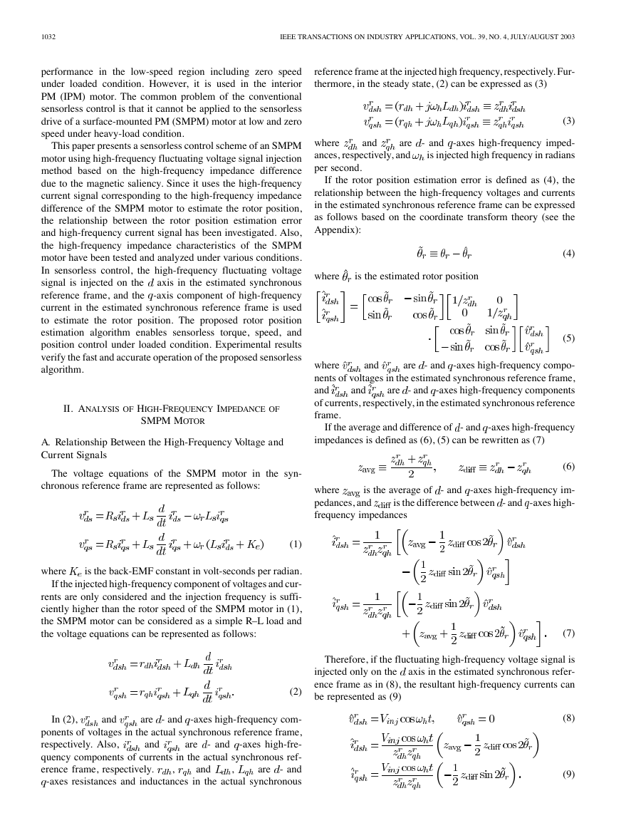
the injection frequency is 550 Hz. As can be seen in the figure,
the -axis high-frequency impedance is larger than that of the
axis. The high-frequency impedance differences (
) between
) at
all magnitudes of the injected high-frequency voltage signals.
-axis high-frequency
As the magnitude is increased,
impedance decreases, but the -axis high-frequency impedance
does not decrease. This is due to the fact that the stator core
-axis winding is already saturated. Therefore,
around the
increasing the magnitude of the injected voltage signal cannot
affect the -axis high-frequency impedance.
the
and
axes are about 30% of the average impedance (
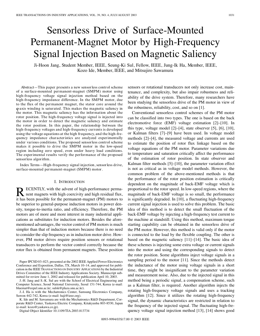
Fig. 1. Relationship between the measurement axis and the actual axis.
axes is not zero (
From (9), it can be known that the - and -axes high-frequency
components of currents in the estimated synchronous reference
frame have the information about the rotor position estimation
error if the high-frequency impedance difference between and
). The -axis high-frequency current
is offset by average high-frequency impedance, and is not zero
even if the rotor position estimation error is zero. On the con-
trary, the -axis high-frequency current becomes zero when the
rotor position estimation error is zero. Therefore, in this paper,
the -axis high-frequency current in (9) is used as an input signal
to the rotor position estimator in order to estimate rotor position
and speed.
B. Measurement of High-Frequency Impedance of SMPM
Motor
In the above section, the information about the rotor position
estimation error can be obtained through a high-frequency
current in the estimated synchronous reference frame if the
high-frequency impedance difference is not zero. Therefore,
in this paper, to investigate the high-frequency impedance
characteristics of an SMPM motor, some impedance measure-
ment tests have been performed. The motor under test is a
commercial 11-kW SMPM motor, and has the parameters as
shown in Table I. Fig. 1 shows the relationship between the
actual axes and the measurement axis. In the measurement of
the high-frequency impedance test, the rotor of SMPM motor
is mechanically locked to prevent the distortion of the signal
by the back-EMF voltage due to the rotor vibration. In Fig. 1,
is the relative
the
axis, which is
position of measurement axis to the actual
axis is the measurement axis, and
�
1034
IEEE TRANSACTIONS ON INDUSTRY APPLICATIONS, VOL. 39, NO. 4, JULY/AUGUST 2003
Fig. 3. High-frequency impedance characteristics at various injection voltages
(550 Hz).
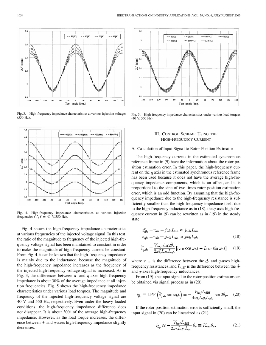
Fig. 5. High-frequency impedance characteristics under various load torques
(40 V, 550 Hz).
III. CONTROL SCHEME USING THE
HIGH-FREQUENCY CURRENT
A. Calculation of Input Signal to Rotor Position Estimator
The high-frequency currents in the estimated synchronous
reference frame in (9) have the information about the rotor po-
sition estimation error. In this paper, the high-frequency cur-
axis in the estimated synchronous reference frame
rent on the
has been used because it does not have the average high-fre-
quency impedance components, which is an offset, and it is
proportional to the sine of two times rotor position estimation
error, which is an odd function. By assuming that the high-fre-
quency impedance due to the high-frequency resistance is suf-
ficiently smaller than the high-frequency impedance itself due
to the high-frequency inductance as in (18), the -axis high-fre-
quency current in (9) can be rewritten as in (19) in the steady
state
(18)
(19)
where
frequency resistances, and
and -axes high-frequency inductances.
is the difference between the - and -axes high-
is the difference between the -
From (19), the input signal to the rotor position estimator can
be obtained via signal process as in (20)
(20)
If the rotor position estimation error is sufficiently small, the
input signal in (20) can be linearized as (21)
(21)
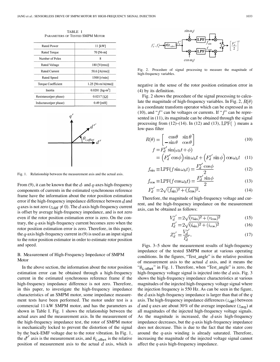
Fig. 4. High-frequency impedance characteristics at various injection
frequencies (V =f = 40 V/550 Hz).
Fig. 4 shows the high-frequency impedance characteristics
at various frequencies of the injected voltage signal. In this test,
the ratio of the magnitude to frequency of the injected high-fre-
quency voltage signal has been maintained to constant in order
to make the magnitude of high-frequency current be constant.
From Fig. 4, it can be known that the high-frequency impedance
is mainly due to the inductance, because the magnitude of
the high-frequency impedance increases as the frequency of
the injected high-frequency voltage signal is increased. As in
Fig. 3, the differences between - and -axes high-frequency
impedance is about 30% of the average impedance at all injec-
tion frequencies. Fig. 5 shows the high-frequency impedance
characteristics under various load torques. The magnitude and
frequency of the injected high-frequency voltage signal are
40 V and 550 Hz, respectively. Even under the heavy loaded
conditions,
the high-frequency impedance difference does
not disappear. It is about 30% of the average high-frequency
impedance. However, as the load torque increases, the differ-
ence between - and -axes high-frequency impedance slightly
decreases.
�
JANG et al.: SENSORLESS DRIVE OF SMPM MOTOR BY HIGH-FREQUENCY SIGNAL INJECTION
1035
Fig. 6. Procedure of signal processing to calculate the input signal to the rotor
position estimator.
Fig. 8. Block diagram of the proposed rotor speed estimator.
Fig. 7. Block diagram of the proposed rotor position estimator.
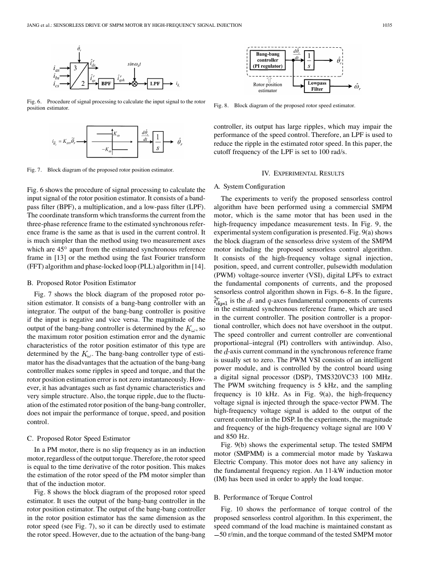
Fig. 6 shows the procedure of signal processing to calculate the
input signal of the rotor position estimator. It consists of a band-
pass filter (BPF), a multiplication, and a low-pass filter (LPF).
The coordinate transform which transforms the current from the
three-phase reference frame to the estimated synchronous refer-
ence frame is the same as that is used in the current control. It
is much simpler than the method using two measurement axes
which are 45 apart from the estimated synchronous reference
frame in [13] or the method using the fast Fourier transform
(FFT) algorithm and phase-locked loop (PLL) algorithm in [14].
B. Proposed Rotor Position Estimator
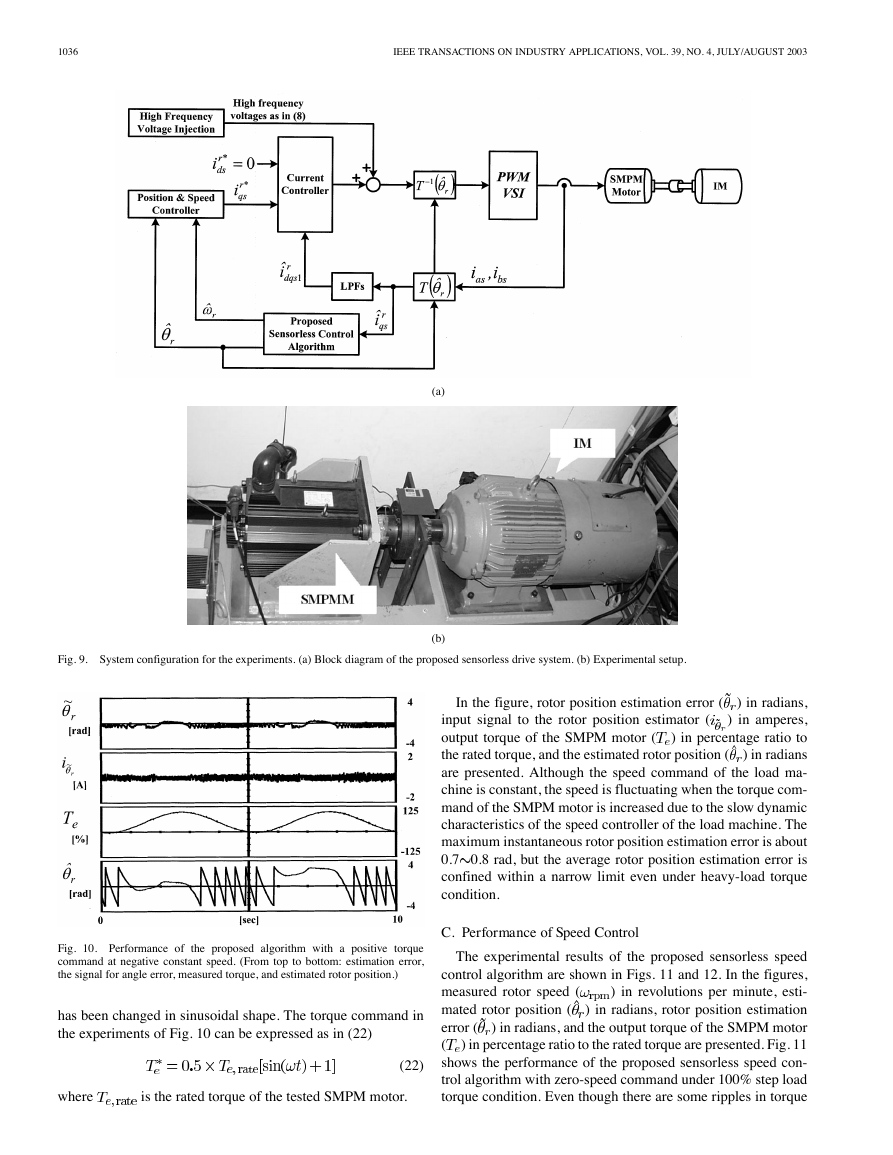
Fig. 7 shows the block diagram of the proposed rotor po-
sition estimator. It consists of a bang-bang controller with an
integrator. The output of the bang-bang controller is positive
if the input is negative and vice versa. The magnitude of the
, so
output of the bang-bang controller is determined by the
the maximum rotor position estimation error and the dynamic
characteristics of the rotor position estimator of this type are
. The bang-bang controller type of esti-
determined by the
mator has the disadvantages that the actuation of the bang-bang
controller makes some ripples in speed and torque, and that the
rotor position estimation error is not zero instantaneously. How-
ever, it has advantages such as fast dynamic characteristics and
very simple structure. Also, the torque ripple, due to the fluctu-
ation of the estimated rotor position of the bang-bang controller,
does not impair the performance of torque, speed, and position
control.
C. Proposed Rotor Speed Estimator
In a PM motor, there is no slip frequency as in an induction
motor, regardless of the output torque. Therefore, the rotor speed
is equal to the time derivative of the rotor position. This makes
the estimation of the rotor speed of the PM motor simpler than
that of the induction motor.
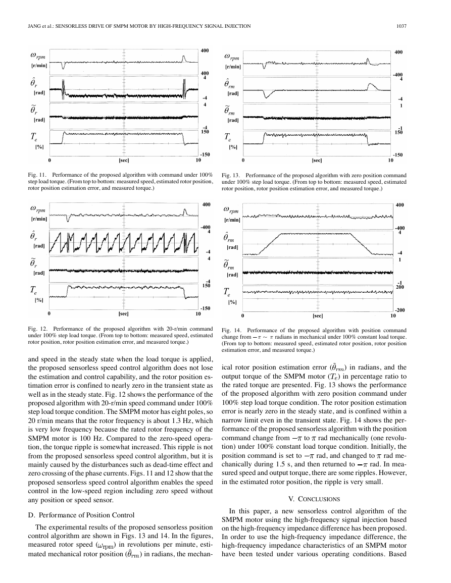
Fig. 8 shows the block diagram of the proposed rotor speed
estimator. It uses the output of the bang-bang controller in the
rotor position estimator. The output of the bang-bang controller
in the rotor position estimator has the same dimension as the
rotor speed (see Fig. 7), so it can be directly used to estimate
the rotor speed. However, due to the actuation of the bang-bang
controller, its output has large ripples, which may impair the
performance of the speed control. Therefore, an LPF is used to
reduce the ripple in the estimated rotor speed. In this paper, the
cutoff frequency of the LPF is set to 100 rad/s.
IV. EXPERIMENTAL RESULTS
A. System Configuration
The experiments to verify the proposed sensorless control
algorithm have been performed using a commercial SMPM
motor, which is the same motor that has been used in the
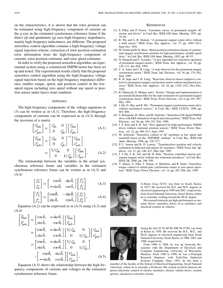
high-frequency impedance measurement tests. In Fig. 9, the
experimental system configuration is presented. Fig. 9(a) shows
the block diagram of the sensorless drive system of the SMPM
motor including the proposed sensorless control algorithm.
It consists of the high-frequency voltage signal
injection,
position, speed, and current controller, pulsewidth modulation
(PWM) voltage-source inverter (VSI), digital LPFs to extract
the fundamental components of currents, and the proposed
sensorless control algorithm shown in Figs. 6–8. In the figure,
is the - and -axes fundamental components of currents
in the estimated synchronous reference frame, which are used
in the current controller. The position controller is a propor-
tional controller, which does not have overshoot in the output.
The speed controller and current controller are conventional
proportional–integral (PI) controllers with antiwindup. Also,
the -axis current command in the synchronous reference frame
is usually set to zero. The PWM VSI consists of an intelligent
power module, and is controlled by the control board using
a digital signal processor (DSP), TMS320VC33 100 MHz.
The PWM switching frequency is 5 kHz, and the sampling
frequency is 10 kHz. As in Fig. 9(a), the high-frequency
voltage signal is injected through the space-vector PWM. The
high-frequency voltage signal is added to the output of the
current controller in the DSP. In the experiments, the magnitude
and frequency of the high-frequency voltage signal are 100 V
and 850 Hz.
Fig. 9(b) shows the experimental setup. The tested SMPM
motor (SMPMM) is a commercial motor made by Yaskawa
Electric Company. This motor does not have any saliency in
the fundamental frequency region. An 11-kW induction motor
(IM) has been used in order to apply the load torque.
B. Performance of Torque Control
Fig. 10 shows the performance of torque control of the
proposed sensorless control algorithm. In this experiment, the
speed command of the load machine is maintained constant as
50 r/min, and the torque command of the tested SMPM motor
�
1036
IEEE TRANSACTIONS ON INDUSTRY APPLICATIONS, VOL. 39, NO. 4, JULY/AUGUST 2003
(a)
(b)
Fig. 9. System configuration for the experiments. (a) Block diagram of the proposed sensorless drive system. (b) Experimental setup.
In the figure, rotor position estimation error (
) in radians,
) in amperes,
input signal to the rotor position estimator (
) in percentage ratio to
output torque of the SMPM motor (
) in radians
the rated torque, and the estimated rotor position (
are presented. Although the speed command of the load ma-
chine is constant, the speed is fluctuating when the torque com-
mand of the SMPM motor is increased due to the slow dynamic
characteristics of the speed controller of the load machine. The
maximum instantaneous rotor position estimation error is about
0.7 0.8 rad, but the average rotor position estimation error is
confined within a narrow limit even under heavy-load torque
condition.
C. Performance of Speed Control
The experimental results of the proposed sensorless speed
control algorithm are shown in Figs. 11 and 12. In the figures,
) in revolutions per minute, esti-
measured rotor speed (
) in radians, rotor position estimation
mated rotor position (
) in radians, and the output torque of the SMPM motor
error (
) in percentage ratio to the rated torque are presented. Fig. 11
(
shows the performance of the proposed sensorless speed con-
trol algorithm with zero-speed command under 100% step load
torque condition. Even though there are some ripples in torque
Fig. 10. Performance of the proposed algorithm with a positive torque
command at negative constant speed. (From top to bottom: estimation error,
the signal for angle error, measured torque, and estimated rotor position.)
has been changed in sinusoidal shape. The torque command in
the experiments of Fig. 10 can be expressed as in (22)
(22)
where
is the rated torque of the tested SMPM motor.
�
JANG et al.: SENSORLESS DRIVE OF SMPM MOTOR BY HIGH-FREQUENCY SIGNAL INJECTION
1037
Fig. 11. Performance of the proposed algorithm with command under 100%
step load torque. (From top to bottom: measured speed, estimated rotor position,
rotor position estimation error, and measured torque.)
Fig. 13. Performance of the proposed algorithm with zero position command
under 100% step load torque. (From top to bottom: measured speed, estimated
rotor position, rotor position estimation error, and measured torque.)
Fig. 12. Performance of the proposed algorithm with 20-r/min command
under 100% step load torque. (From top to bottom: measured speed, estimated
rotor position, rotor position estimation error, and measured torque.)
and speed in the steady state when the load torque is applied,
the proposed sensorless speed control algorithm does not lose
the estimation and control capability, and the rotor position es-
timation error is confined to nearly zero in the transient state as
well as in the steady state. Fig. 12 shows the performance of the
proposed algorithm with 20-r/min speed command under 100%
step load torque condition. The SMPM motor has eight poles, so
20 r/min means that the rotor frequency is about 1.3 Hz, which
is very low frequency because the rated rotor frequency of the
SMPM motor is 100 Hz. Compared to the zero-speed opera-
tion, the torque ripple is somewhat increased. This ripple is not
from the proposed sensorless speed control algorithm, but it is
mainly caused by the disturbances such as dead-time effect and
zero crossing of the phase currents. Figs. 11 and 12 show that the
proposed sensorless speed control algorithm enables the speed
control in the low-speed region including zero speed without
any position or speed sensor.
Fig. 14. Performance of the proposed algorithm with position command
change from �� � � radians in mechanical under 100% constant load torque.
(From top to bottom: measured speed, estimated rotor position, rotor position
estimation error, and measured torque.)
) in radians, and the
ical rotor position estimation error (
) in percentage ratio to
output torque of the SMPM motor (
the rated torque are presented. Fig. 13 shows the performance
of the proposed algorithm with zero position command under
100% step load torque condition. The rotor position estimation
error is nearly zero in the steady state, and is confined within a
narrow limit even in the transient state. Fig. 14 shows the per-
formance of the proposed sensorless algorithm with the position
rad mechanically (one revolu-
command change from
tion) under 100% constant load torque condition. Initially, the
rad me-
position command is set to
rad. In mea-
chanically during 1.5 s, and then returned to
sured speed and output torque, there are some ripples. However,
in the estimated rotor position, the ripple is very small.
rad, and changed to
to
V. CONCLUSIONS
D. Performance of Position Control
The experimental results of the proposed sensorless position
control algorithm are shown in Figs. 13 and 14. In the figures,
) in revolutions per minute, esti-
measured rotor speed (
) in radians, the mechan-
mated mechanical rotor position (
In this paper, a new sensorless control algorithm of the
SMPM motor using the high-frequency signal injection based
on the high-frequency impedance difference has been proposed.
In order to use the high-frequency impedance difference, the
high-frequency impedance characteristics of an SMPM motor
have been tested under various operating conditions. Based
�
1038
IEEE TRANSACTIONS ON INDUSTRY APPLICATIONS, VOL. 39, NO. 4, JULY/AUGUST 2003
on the characteristics, it is shown that the rotor position can
be estimated using high-frequency component of currents on
axis in the estimated synchronous reference frame if the
the
direct ( ) and quadrature ( ) axes high-frequency impedances,
mainly high-frequency inductances, are different. The proposed
sensorless control algorithm contains a high-frequency voltage
signal injection scheme, extraction of rotor position estimation
error information from the high-frequency component of
currents, rotor position estimator, and rotor speed estimator.
In order to verify the proposed sensorless algorithm, an exper-
imental system using a commercial SMPM motor has been set
up and tested. The experimental results clarify that the proposed
sensorless control algorithm using the high-frequency voltage
signal injection based on the high-frequency impedance differ-
ence enables torque, speed, and position control in the low-
speed region including zero speed without any speed or posi-
tion sensor under heavy-load condition.
APPENDIX
The high-frequency components of the voltage equations in
(3) can be written as in (A.1). Therefore, the high-frequency
components of currents can be expressed as in (A.2) through
the inversion of a matrix
(A.1)
(A.2)
The relationship between the variables in the actual syn-
chronous reference frame and variables in the estimated
synchronous reference frame can be written as in (A.3) and
(A.4)
(A.3)
(A.4)
Equation (A.2) can be expressed as in (A.5) using (A.3) and
(A.4)
Equation (A.5) shows the relationship between the high-fre-
quency components of currents and voltages in the estimated
synchronous reference frame.
(A.5)
REFERENCES
[1] P. Pillay and P. Freere, “Literature survey of permanent magnet AC
motors and drives,” in Conf. Rec. IEEE-IAS Annu. Meeting, 1991, pp.
74–84.
[2] R. Wu and G. R. Slemon, “A permanent magnet motor drive without
a shaft sensor,” IEEE Trans. Ind. Applicat., vol. 27, pp. 1005–1011,
Sept./Oct. 1991.
[3] M. Naidu and B. K. Bose, “Rotor position estimation scheme of a perma-
nent magnet synchronous machine for high performance variable speed
drive,” in Conf. Rec. IEEE-IAS Annu. Meeting, 1992, pp. 48–53.
[4] N. Ertugrul and P. Acarnley, “A new algorithm for sensorless operation
of permanent magnet motors,” IEEE Trans. Ind. Applicat., vol. 30, pp.
126–133, Jan./Feb. 1994.
[5] L. A. Jones and J. H. Lang, “A state observer for the permanent-magnet
synchronous motor,” IEEE Trans. Ind. Electron., vol. 36, pp. 374–382,
June 1989.
[6] R. B. Sepe and J. H. Lang, “Real-time observer-based (adaptive) con-
trol of a permanent-magnet synchronous motor without mechanical sen-
sores,” IEEE Trans. Ind. Applicat., vol. 28, pp. 1345–1352, Nov./Dec.
1992.
[7] R. Dhauoadi, N. Mohan, and L. Norum, “Design and implementation of
an extended Kalman filter for the state estimation of a permanent magnet
synchronous motor,” IEEE Trans. Power Electron., vol. 6, pp. 491–497,
May 1991.
[8] J. Hu, D. Zhu, and B. Wu, “Permanent magnet synchronous motor drive
without mechanical sensors,” in Conf. Rec. IEEE CCECE, 1996, pp.
603–606.
[9] S. Bolognani, R. Oboe, and M. Zigliotto, “Sensorless full-digital PMSM
drive with EKF estimation of speed and rotor position,” IEEE Trans. Ind.
Electron., vol. 46, pp. 184–191, Feb. 1999.
[10] J. S. Kim and S. K. Sul, “New approach for high performance PMSM
drives without rotational position sensors,” IEEE Trans. Power Elec-
tron., vol. 12, pp. 904–911, Sept. 1997.
[11] M. Schroedl, “Sensorless control of AC machines at low speed and
standstill based on the ‘INFORM’ method,” in Conf. Rec. IEEE-IAS
Annu. Meeting, 1996, pp. 270–277.
[12] P. L. Jansen and R. D. Lorenz, “Transducerless position and velocity
estimation in induction and salient AC machines,” IEEE Trans. Ind. Ap-
plicat., vol. 31, pp. 240–247, Mar./Apr. 1995.
[13] J. I. Ha, S. K. Sul, and M. H. Park, “Position controlled interior per-
manent magnet motor without any rotational transducer,” in Conf. Rec.
IEEE-2K, 2000, pp. 396–399.
[14] T. Aihara, A. Toba, T. Yanase, A. Mashimo, and K. Endo, “Sensorless
torque control of salient-pole synchronous motor at zero-speed opera-
tion,” IEEE Trans. Power Electron., vol. 14, pp. 202–208, Jan. 1999.
Ji-Hoon Jang (S’01) was born in Seoul, Korea,
in 1975. He received the B.S. and M.S. degrees in
electrical engineering in 1999 and 2001, respectively,
from Seoul National University, Seoul, Korea, where
he is currently working toward the Ph.D. degree.
His research interests are high-performance ac ma-
chine drives, sensorless drives of ac machines, and
electrical systems in vehicles.
Seung-Ki Sul (S’78–M’80–SM’98–F’00) was born
in Korea in 1958. He received the B.S., M.S., and
Ph.D. degrees in electrical engineering from Seoul
National University, Seoul, Korea, in 1980, 1983, and
1986, respectively.
From 1986 to 1988, he was an Associate Re-
searcher with the Department of Electrical and
Computer Engineering, University of Wisconsin,
Madison. From 1988 to 1990, he was a Principal
Research Engineer with Gold-Star
Industrial
Systems Company. Since 1991, he has been a
member of the faculty of the School of Electrical Engineering, Seoul National
University, where he is currently a Professor. His current research interests are
power-electronic control of electric machines, electric vehicle drives, custom
powers, and power-converter circuits.
�


 2023年江西萍乡中考道德与法治真题及答案.doc
 2012年重庆南川中考生物真题及答案.doc
 2013年江西师范大学地理学综合及文艺理论基础考研真题.doc
 2020年四川甘孜小升初语文真题及答案I卷.doc
 2020年注册岩土工程师专业基础考试真题及答案.doc
 2023-2024学年福建省厦门市九年级上学期数学月考试题及答案.doc
 2021-2022学年辽宁省沈阳市大东区九年级上学期语文期末试题及答案.doc
 2022-2023学年北京东城区初三第一学期物理期末试卷及答案.doc
 2018上半年江西教师资格初中地理学科知识与教学能力真题及答案.doc
 2012年河北国家公务员申论考试真题及答案-省级.doc
 2020-2021学年江苏省扬州市江都区邵樊片九年级上学期数学第一次质量检测试题及答案.doc
 2022下半年黑龙江教师资格证中学综合素质真题及答案.doc