IOP Conference Series: Materials Science and EngineeringPAPER • OPEN ACCESSDesign of PID temperature control system basedon STM32To cite this article: Jianxin Zhang et al 2018 IOP Conf. Ser.: Mater. Sci. Eng. 322 072020 View the article online for updates and enhancements.Related contentThe Integrated Electro-Mechanical Drive:Appendix BB T Fijalkowski and J Tutaj-A SIMPLE TEMPERATURE CONTROLSYSTEM FOR PHOTOGRAPHIC DARK-ROOMSWilliam C. Miller-Development of Temperature AcquisitionSystem based on STM32Jian HUANG-This content was downloaded from IP address 113.140.11.126 on 12/03/2019 at 08:55�
Design of PID temperature control system based on STM32
Jianxin Zhang1,2,3,4,*, Hailin Li1,3, Kai Ma1,3, Liang Xue1,3, Bianhua Han1,3,
Yuemeng Dong2,3, Yue Tan2,3, Chengru Gu2,3
1 Tianjin Key Laboratory of Optoelectronic Detection Technology and Systems,
Tianjin Polytechnic University, Tianjin, China
2 Tianjin Key Laboratory of Advanced Electrical Engineering and Energy Technology,
Tianjin Polytechnic University, Tianjin, China
3 Engineering Research Center of High Power Semiconductor Lighting Application
System Education Department, Tianjin Polytechnic University, Tianjin, China
4 State Key Laboratory of Hollow Fiber Membrane Materials and Processes, Tianjin
Polytechnic University, Tianjin, China
*Corresponding author e-mail: assen_zhjx@126.com
Abstract. A rapid and high-accuracy temperature control system was designed using
proportional-integral-derivative (PID) control algorithm with STM32 as micro-
controller unit (MCU). The temperature control system can be applied in the fields
which have high requirements on the response speed and accuracy of temperature
control. The temperature acquisition circuit in system adopted Pt1000 resistance
thermometer as temperature sensor. Through this acquisition circuit, the monitoring
actual temperature signal could be converted into voltage signal and transmitted into
MCU. A TLP521-1 photoelectric coupler was matched with BD237 power transistor
to drive the thermoelectric cooler (TEC) in FTA951 module. The effective electric
power of TEC was controlled by the pulse width modulation (PWM) signals which
generated by MCU. The PWM signal parameters could be adjusted timely by PID
algorithm according to the difference between monitoring actual temperature and set
temperature. The upper computer was used to input the set temperature and monitor
the system running state via serial port. The application experiment results show that
the temperature control system is featured by simple structure, rapid response speed,
good stability and high temperature control accuracy with the error less than ±0.5°C.
1. Introduction
As an important parameter in industrial manufacture [1] and scientific experiment [2], temperature
needs to be measured and controlled rapidly with high accuracy. Otherwise, the distinct temperature
errors will be harmful to the performance and precision of the whole measurement system [3],
especially in the field of modern instrument. For example, it is very important to correctly obtain the
accelerated lifetime prediction [4] and photo-electro-thermal properties [5] of LED light source
through providing a constant temperature environment with high accuracy and rapid response speed.
In another instance, the core parts of fiber optic gyroscope (FOG) is also sensitive to environment
temperature [6], a slight temperature change can cause the zero drift of FOG, so it is necessary to
provide accurate temperature control or temperature compensation [7]. Lots of practical applications
show that a rapid and high-accuracy temperature control system is worthy of further investigation.
1
ContentfromthisworkmaybeusedunderthetermsoftheCreativeCommonsAttribution3.0licence.Anyfurtherdistributionofthisworkmustmaintainattributiontotheauthor(s)andthetitleofthework,journalcitationandDOI.PublishedunderlicencebyIOPPublishingLtd1234567890‘’“”SAMSE IOP PublishingIOP Conf. Series: Materials Science and Engineering 322 (2018) 072020 doi:10.1088/1757-899X/322/7/072020�
Traditionally, analog circuit is used for temperature control in most cases. In this circuit,
electromagnetic relay is usually chosen to control the switchover between heating module and cooling
module, as well as controlling the working time and frequency of the two modules, for constant
temperature. However, this method has many weaknesses, such as low accuracy of temperature
control, great inertia, apparent lag and complex circuit design. In addition, it also has the deficiencies
in temperature uniformity, stability and response speed, and so on [8].
In this paper, a thermoelectric cooler (TEC) was adopted to provide a new method of working
pattern switchover between heating and cooling. The effective electric power of heating or cooling
could be adjusted through regulating the pulse duration ratio of pulse width modulation (PWM)
signals about TEC driving voltage. The PWM signals could be automatically controlled by
proportional-integral-derivative (PID) algorithm. In order to increase the precision of temperature
measurement, the voltage ripple of temperature acquisition circuit was decreased by a passive filter.
The STM32 was used as micro-controller unit (MCU) for building a rapid and high-accuracy
temperature control system with PID algorithm. Finally, the response speed and stabilization accuracy
of temperature control were evaluated by application experiment.
2. Structure design of sample holder and overall design of temperature control system
2.1. Structure design of sample holder
In general, temperature control system need to equip a sample holder with the working patterns of
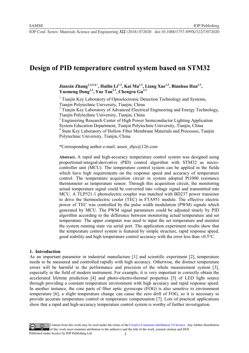
heating, cooling and constant temperature. A FTA951 heating and cooling module, as shown in Figure
1, is selected as the execution unit for temperature control. The TEC in FTA951 module can execute
the cooling pattern and rapidly drop the temperature of sample holder when provided with forward
direct current. When TEC is driven with reverse current, it can execute the heating pattern and rise the
temperature of sample holder in a short time. The TEC has high working reliability because FTA951
module adopts the design of quake-proof and shock-proof. There is a plane sample holder for
installing the test sample on one side of TEC. On the other side of TEC, a heat sink with fan is
installed to improve the efficiency of heating and cooling [9].
The sample holder needs to be made of copper material with high thermal conductivity capacity.
There are two probe-holes in sample holder, through which temperature sensing probes can be send to
the central position. One probe-hole is very close to the surface of sample holder and regularly gives
the feedback of actual temperature T1. The other one is very close to TEC and collects the referential
temperature T2 to judge whether the sample holder is in thermal steady state.
Figure 1. Structure of FTA951 heating and cooling module.
In order to make the actual temperature T1 of sample holder reach the set temperature T0 quickly
without obvious overshoot, the effective power of TEC is high when there is a big difference between
T1 and T0; when T1 is approaching to T0, the effective power is declining accordingly; when T1 reaches
T0, the effective power is reduced to the level for maintaining slight temperature fluctuation and
maintains T1 around T0 for long times. Only when the difference between T1 and T2 is less than ±0.5°C,
the temperature of sample holder is deemed to be in thermal steady state.
2
1234567890‘’“”SAMSE IOP PublishingIOP Conf. Series: Materials Science and Engineering 322 (2018) 072020 doi:10.1088/1757-899X/322/7/072020�
2.2. Overall design of temperature control system
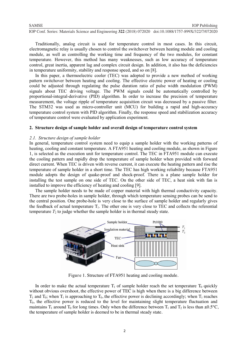
The overall design frame of temperature control system is shown in Figure 2. The temperature
acquisition circuit is designed to convert temperature signal into amplified voltage signal.
STM32F103VET6 is used as MCU which can obtain the set temperature T0 given by PC soft through
RS232 serial port and regularly monitor the present actual temperature T1 of sample holder through
temperature acquisition circuit. After each acquisition of T1, MCU immediately calculates the
temperature difference between T1 and T0. According to the plus or minus of temperature difference,
MCU can automatically control the pin switch of electromagnetic relay in temperature control
execution circuit to adjust the current direction of TEC and execute working pattern switchover
between heating and cooling. In addition, according to the absolute value of temperature difference,
MCU runs digital PID algorithm to timely adjust the pulse duration ratio of PWM signals which can
control the effective power of TEC by temperature control circuit [10]. Finally, the dynamic
adjustment of TEC effective power based on the temperature difference can accurately keep the
temperature of sample holder around the set temperature T0. During the controlling process, all the
temperature data can be timely sent to PC soft through RS232 serial port, and then the present actual
temperature values and their variation curve are displayed on the PC soft.
Figure 2. Frame diagram of overall design for temperature control system.
The temperature control system mainly provides a mandatory stable environment temperature to
meet the requirements of LED photo-electro-thermal properties measurement in steady state. The set
temperature for measurement should be continuously adjustable and cover the range of 20°C-80°C.
When the temperature of sample holder rises from 20°C to 80°C or drops from 80°C to 20°C, the
elapsed time for reaching the thermal steady state of target temperature should be less than 140s to
ensure a rapid response speed of temperature control. In thermal steady state, the maximum error
between actual temperature and set temperature of sample holder should be less than ±0.5°C.
3. Circuit design of temperature control system
3.1. Temperature acquisition circuit
The temperature acquisition circuit is mainly used for the real-time collection and feedback of the
actual temperature of sample holder. In the circuit, Pt1000 platinum thermal resistor is used as
temperature sensor. The temperature coefficient of resistance (TCR) of Pt1000 is 0.003851 °C-1, and
accuracy range is from ±0.05 °C to ±0.5°C. As a temperature sensor, Pt1000 has the advantages of
stable electrical performance, vibration endurance, good reliability, high accuracy, sensitivity and long
life, etc. Therefore, Pt1000 is qualified for the design of temperature acquisition circuit. The common-
mode rejection ratio (CMRR) is usually defined as the ratio of common-mode interference signal
acting on the system to the different-mode signal needed by the system to have the same output.
Higher CMRR means that the system has stronger ability to resist common interference. AD8221 is a
gain-programmable high-performance instrument amplifier and has the remarkable common-mode
rejection performance. When the gain is 1, AD8221 can keep the minimum common-mode rejection
ratio of 80dB at each level until the frequency reaches 10 kHz, thus it can resist common-mode
interference effectively and is very suitable for the sensor interface circuit with differential input. In
addition, AD8221 is also featured by low voltage offset, low offset drift, low grain drift and high gain
accuracy, so it is a good choice for direct current performance application such as bridge signal
3
1234567890‘’“”SAMSE IOP PublishingIOP Conf. Series: Materials Science and Engineering 322 (2018) 072020 doi:10.1088/1757-899X/322/7/072020�
conditioning. Therefore, this circuit uses Pt1000 and AD8221 to enable the collection and
amplification of temperature signal respectively.
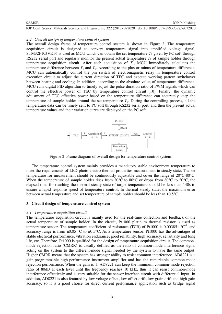
Figure 3. Temperature acquisition circuit.
The temperature acquisition circuit, as shown in Figure 3, is mainly composed of H-bridge circuit
and differential operational amplification circuit with passive filter. In Figure 3, P1 is the terminal for
connecting with Pt1000 temperature sensor. When Pt1000 is in ice-water mixture (0°C), the
temperature is corrected by adjusting the actual resistance of adjustable resistor RP4 to make the
output voltage Vout of AD8221 equal to 0 V. The resistance of Pt1000 increases with temperature
rising, which changes the divided voltage in H-bridge circuit. As a result, the voltage difference
between +IN and -IN of AD8221 also changes accordingly. The differential amplification factor can
be obtained through high-accuracy assistance R21. The amplified output voltage Vout is input into
analog-to-digital converter of MCU and translated into temperature value. In this circuit, a passive
filter is used to decline RF energy as much as possible and suppress RF interference before the
amplifier. A good RF interference suppression can balance the AC signal between each input and
ground, and obtain enough high input impedance in the measuring bandwidth, which can maintain the
load capacity of input signal source.
3.2. Temperature control circuit
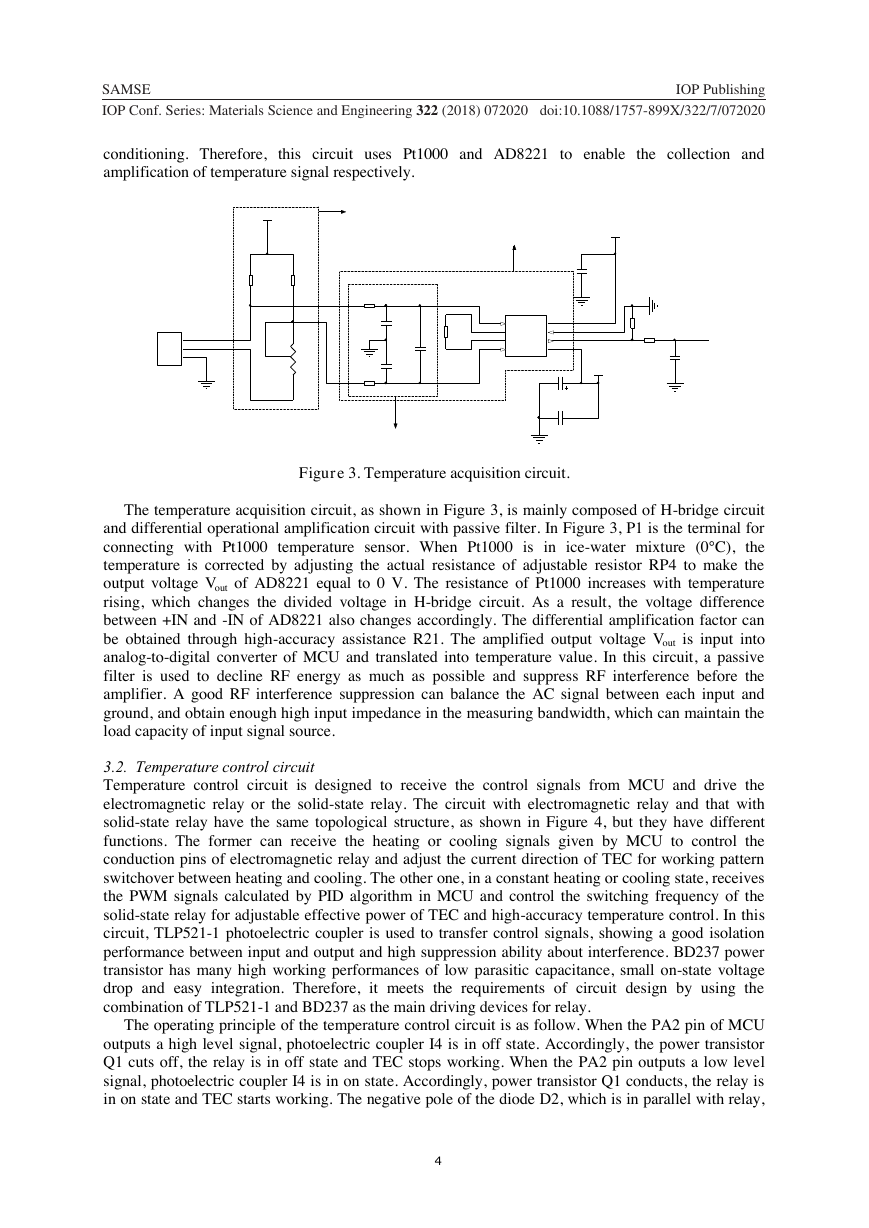
Temperature control circuit is designed to receive the control signals from MCU and drive the
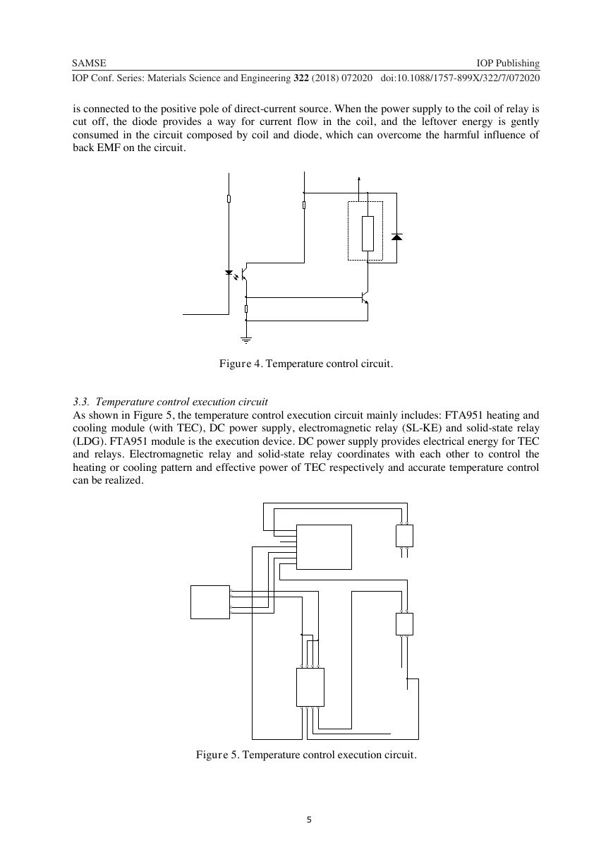
electromagnetic relay or the solid-state relay. The circuit with electromagnetic relay and that with
solid-state relay have the same topological structure, as shown in Figure 4, but they have different
functions. The former can receive the heating or cooling signals given by MCU to control the
conduction pins of electromagnetic relay and adjust the current direction of TEC for working pattern
switchover between heating and cooling. The other one, in a constant heating or cooling state, receives
the PWM signals calculated by PID algorithm in MCU and control the switching frequency of the
solid-state relay for adjustable effective power of TEC and high-accuracy temperature control. In this
circuit, TLP521-1 photoelectric coupler is used to transfer control signals, showing a good isolation
performance between input and output and high suppression ability about interference. BD237 power
transistor has many high working performances of low parasitic capacitance, small on-state voltage
drop and easy integration. Therefore, it meets the requirements of circuit design by using the
combination of TLP521-1 and BD237 as the main driving devices for relay.
The operating principle of the temperature control circuit is as follow. When the PA2 pin of MCU
outputs a high level signal, photoelectric coupler I4 is in off state. Accordingly, the power transistor
Q1 cuts off, the relay is in off state and TEC stops working. When the PA2 pin outputs a low level
signal, photoelectric coupler I4 is in on state. Accordingly, power transistor Q1 conducts, the relay is
in on state and TEC starts working. The negative pole of the diode D2, which is in parallel with relay,
4
1234567890‘’“”SAMSE IOP PublishingIOP Conf. Series: Materials Science and Engineering 322 (2018) 072020 doi:10.1088/1757-899X/322/7/072020GNDVCC_-5VC240.1uFGNDR251kC280.1uFGNDADC123_IN1R214.94kC80.01uFC70.01uFGNDR151kR161k+5VGNDC120.1uF10uF/16VC200.1uFC19-IN1Rg2Rg3+IN4+VS8Vout7RES6-VS5U1U1_AD8221VCC_+5VR41kR81kGND123P1Header 3R261k2kRP4T+T-H-bridge circuitDifferential operational amplification circuitPassive filter�
is connected to the positive pole of direct-current source. When the power supply to the coil of relay is
cut off, the diode provides a way for current flow in the coil, and the leftover energy is gently
consumed in the circuit composed by coil and diode, which can overcome the harmful influence of
back EMF on the circuit.
Figure 4. Temperature control circuit.
3.3. Temperature control execution circuit
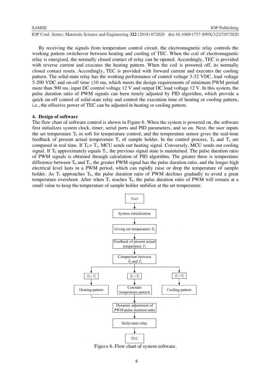
As shown in Figure 5, the temperature control execution circuit mainly includes: FTA951 heating and
cooling module (with TEC), DC power supply, electromagnetic relay (SL-KE) and solid-state relay
(LDG). FTA951 module is the execution device. DC power supply provides electrical energy for TEC
and relays. Electromagnetic relay and solid-state relay coordinates with each other to control the
heating or cooling pattern and effective power of TEC respectively and accurate temperature control
can be realized.
Figure 5. Temperature control execution circuit.
5
1234567890‘’“”SAMSE IOP PublishingIOP Conf. Series: Materials Science and Engineering 322 (2018) 072020 doi:10.1088/1757-899X/322/7/0720204312I4TLP521-1R31470R3210KR3310KGND1Q1BD237D21N4007PA2VCC_3.3VVCC_12V+-(1)Electromagnetic relay or solid-state relayREDLBLACKNGNDCOMCOMYELLOWV+REDV+U2-TE+FAN-+U1DC power supplySwitchLDGSL-KETECsignal input+12VHeating or coolingU3U5NL1243U413427568PWMpattern signal input�
By receiving the signals from temperature control circuit, the electromagnetic relay controls the
working pattern switchover between heating and cooling of TEC. When the coil of electromagnetic
relay is energized, the normally closed contact of relay can be opened. Accordingly, TEC is provided
with reverse current and executes the heating pattern. When the coil is powered off, its normally
closed contact resets. Accordingly, TEC is provided with forward current and executes the cooling
pattern. The solid-state relay has the working performance of control voltage 3-32 VDC, load voltage
5-200 VDC and on-off time ≤10 ms, which meets the design requirements of minimum PWM period
more than 500 ms, input DC control voltage 12 V and output DC load voltage 12 V. In this system, the
pulse duration ratio of PWM signals can been timely adjusted by PID algorithm, which provide a
quick on-off control of solid-state relay and control the execution time of heating or cooling pattern,
i.e., the effective power of TEC can be adjusted in heating or cooling pattern.
4. Design of software
The flow chart of software control is shown in Figure 6. When the system is powered on, the software
first initializes system clock, timer, serial ports and PID parameters, and so on. Next, the user inputs
the set temperature T0 in soft for temperature control, and the temperature sensor gives the real-time
feedback of present actual temperature T1 of sample holder. In the control process, T0 and T1 are
compared in real time. If T0 > T1, MCU sends out heating signal. Conversely, MCU sends out cooling
signal. If T0 approximately equals T1, the previous signal state is maintained. The pulse duration ratio
of PWM signals is obtained through calculation of PID algorithm. The greater there is temperature
difference between T0 and T1, the greater PWM signal has the pulse duration ratio, and the longer high
electrical level lasts in a PWM period, which can rapidly raise or drop the temperature of sample
holder. As T1 approaches T0, the pulse duration ratio of PWM declines gradually to avoid a great
temperature overshoot. After when T1 reaches T0, the pulse duration ratio of PWM will remain at a
small value to keep the temperature of sample holder stabilize at the set temperature.
Figure 6. Flow chart of system software.
6
1234567890‘’“”SAMSE IOP PublishingIOP Conf. Series: Materials Science and Engineering 322 (2018) 072020 doi:10.1088/1757-899X/322/7/072020�
5. PID algorithm and its parameter adjustment
PID algorithm is a control algorithm with foreseeability. For the controlled object, PID algorithm
considers not only its current status values but also its historical status values in past time and its
recency status values in the future [11]. The three kinds of value decide collaboratively the present
output control signal. The calculation result of PID algorithm is a number which is used to adjust the
operation of controlled object, such as different power of the heater, open degree of valve, and so on.
Normally, the output is in the form of PWM signal, which meets the design requirements by changing
the pulse duration ratio of output control signal as needed.
Figure 7 is PID control schematic diagram. After the set temperature T0 is given by user on PC soft,
PID algorithm runs immediately and reads the feedback value of present actual temperature T1 about
controlled object in real time. Subsequently, the temperature difference between T0 and T1 is
calculated. Accordingly, the historical bias, current bias and recency bias of overall system is obtained.
After integral, proportion and differential calculations about the three biases, MCU outputs a PWM
signal with variable pulse duration ratio to conduct the next temperature change direction and range.
And soon, the present actual temperature T1 of controlled object can rapidly reach the set temperature
T0 and be steadily kept to be constant temperature.
Figure 7. Schematic diagram of PID control algorithm.
The system adopts the positional PID control algorithm:
Let
Thus
,
(1)
(2)
(3)
Where Ek is the sampling deviation of this time, Ek-1 is the sampling deviation of last time, Kp is scale
factor, ti is integral time constant, td is differential time constant, and t is sampling period. And out0 is
set a non-zero constant to ensure the output signal not to be 0 when Ek is 0. Otherwise, when the
present actual temperature equals the set temperature, the output signal of PID control algorithm will
be 0, and the system will be in uncontrolled status without control signal.
In Eq. (3), Kp, ti, td and t are main control parameters of PID algorithm, and the determination of the
values about these parameters is the key design of temperature control system. Temperature control
system is usually a typical lag inertial system, so the trial-and-error method can be employed to
7
1234567890‘’“”SAMSE IOP PublishingIOP Conf. Series: Materials Science and Engineering 322 (2018) 072020 doi:10.1088/1757-899X/322/7/072020+OPTOTRIACUser settingsEHistorical biasCurrent biasRecency biasPower supplyControl objectSensorTTPID contronl algorithmPWM01T0-T1k=npkikdkk10k0()()(())outKEKEKEEoutipi(/)KKttdpd(/)KKttnpkpikpdkk-10k0()((/))((/)())outKEKttEKttEEout�



 2023年江西萍乡中考道德与法治真题及答案.doc
 2012年重庆南川中考生物真题及答案.doc
 2013年江西师范大学地理学综合及文艺理论基础考研真题.doc
 2020年四川甘孜小升初语文真题及答案I卷.doc
 2020年注册岩土工程师专业基础考试真题及答案.doc
 2023-2024学年福建省厦门市九年级上学期数学月考试题及答案.doc
 2021-2022学年辽宁省沈阳市大东区九年级上学期语文期末试题及答案.doc
 2022-2023学年北京东城区初三第一学期物理期末试卷及答案.doc
 2018上半年江西教师资格初中地理学科知识与教学能力真题及答案.doc
 2012年河北国家公务员申论考试真题及答案-省级.doc
 2020-2021学年江苏省扬州市江都区邵樊片九年级上学期数学第一次质量检测试题及答案.doc
 2022下半年黑龙江教师资格证中学综合素质真题及答案.doc