Recommended Settings Document
ADV7611
ADV7611
Register Settings Recommendations
Revision 1.4
January 2014
�
ADV7611
TABLE OF CONTENTS
Register Settings Recommendations
2.1
2.2
Introduction ........................................................................................................................................................................................................................ 3
Legal Terms and Conditions ............................................................................................................................................................................................. 3
Revision History ................................................................................................................................................................................................................. 3
1
ADV7611 I2C Addresses ....................................................................................................................................................................................... 4
Recommended Initialization Settings .................................................................................................................................................................. 4
2
Initialization Settings for HDMI Mode ........................................................................................................................................................ 4
Dynamic Settings for HDMI .......................................................................................................................................................................... 5
Hot Plug Assert ....................................................................................................................................................................................... 5
Free-run Operation ................................................................................................................................................................................ 5
Power Down modes ............................................................................................................................................................................... 6
Packet Detection ..................................................................................................................................................................................... 6
Equalizer Settings ................................................................................................................................................................................... 9
Low Frequency Formats ........................................................................................................................................................................ 9
2.2.1
2.2.2
2.2.3
2.2.4
2.2.5
2.2.6
Rev. 1.4 | Page 2 of 11
�
ADV7611
Register Settings Recommendations
INTRODUCTION
This document describes ADI register setting recommendations and adjustments for the ADV7611. This document must be used in
conjunction with the latest Hardware Manual / User Guide and Software Manual.
LEGAL TERMS AND CONDITIONS
Information furnished by Analog Devices is believed to be accurate and reliable. However, no responsibility is assumed by Analog
Devices for its use, nor for any infringements of patents or other rights of third parties that may result from its use. No license is granted
by implication or otherwise under any patent or patent rights of Analog Devices. Trademarks and registered trademarks are the property
of their respective owners. Information contained within this document is subject to change without notice. Software or hardware
provided by Analog Devices may not be disassembled, decompiled or reverse engineered. Analog Devices’ standard terms and conditions
for products purchased from Analog Devices can be found at:
http://www.analog.com/en/content/analog_devices_terms_and_conditions/fca.html.
REVISION HISTORY
1/14—Rev. 1.3 to Rev. 1.4
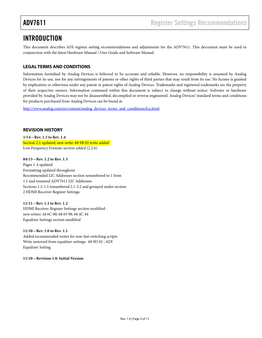
Section 2.1 updated; new write: 68 9B 03 write added
Low Frequency Formats section added (2.2.6)
04/13—Rev. 1.2 to Rev. 1.3
Pages 1-4 updated
Formatting updated throughout
Recommended I2C Addresses section renumbered to 1 from
1.1 and renamed ADV7611 I2C Addresses
Sections 1.2-1.3 renumbered 2.1-2.2 and grouped under section
2 HDMI Receiver Register Settings
11/11—Rev. 1.1 to Rev. 1.2
HDMI Receiver Register Settings section modified :
new writes: 44 6C 00; 68 03 98; 68 4C 44
Equalizer Settings section modified
11/10—Rev. 1.0 to Rev. 1.1
Added recommended writes for non-fast switching scripts
Write removed from equalizer settings: 68 9D 02 ; ADI
Equalizer Setting
11/10—Revision 1.0: Initial Version
Rev. 1.4 | Page 3 of 11
�
ADV7611
Register Settings Recommendations
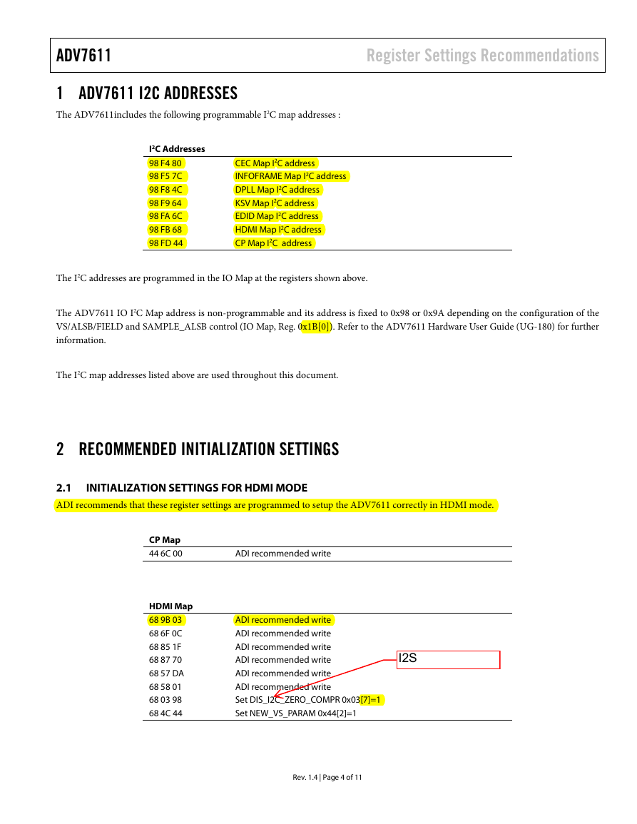
1 ADV7611 I2C ADDRESSES
The ADV7611includes the following programmable I2C map addresses :
I2C Addresses
98 F4 80
98 F5 7C
98 F8 4C
98 F9 64
98 FA 6C
98 FB 68
98 FD 44
CEC Map I2C address
INFOFRAME Map I2C address
DPLL Map I2C address
KSV Map I2C address
EDID Map I2C address
HDMI Map I2C address
CP Map I2C address
The I2C addresses are programmed in the IO Map at the registers shown above.
The ADV7611 IO I2C Map address is non-programmable and its address is fixed to 0x98 or 0x9A depending on the configuration of the
VS/ALSB/FIELD and SAMPLE_ALSB control (IO Map, Reg. 0x1B[0]). Refer to the ADV7611 Hardware User Guide (UG-180) for further
information.
The I2C map addresses listed above are used throughout this document.
2 RECOMMENDED INITIALIZATION SETTINGS
2.1
ADI recommends that these register settings are programmed to setup the ADV7611 correctly in HDMI mode.
INITIALIZATION SETTINGS FOR HDMI MODE
CP Map
44 6C 00
ADI recommended write
HDMI Map
68 9B 03
68 6F 0C
68 85 1F
68 87 70
68 57 DA
68 58 01
68 03 98
68 4C 44
ADI recommended write
ADI recommended write
ADI recommended write
ADI recommended write
ADI recommended write
ADI recommended write
Set DIS_I2C_ZERO_COMPR 0x03[7]=1
Set NEW_VS_PARAM 0x44[2]=1
Rev. 1.4 | Page 4 of 11
�
ADV7611
Register Settings Recommendations
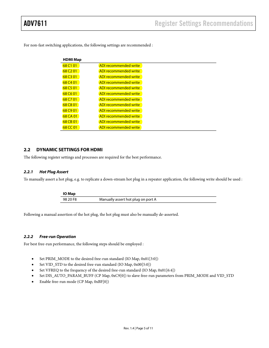
For non-fast switching applications, the following settings are recommended :
HDMI Map
68 C1 01
68 C2 01
68 C3 01
68 C4 01
68 C5 01
68 C6 01
68 C7 01
68 C8 01
68 C9 01
68 CA 01
68 CB 01
68 CC 01
ADI recommended write
ADI recommended write
ADI recommended write
ADI recommended write
ADI recommended write
ADI recommended write
ADI recommended write
ADI recommended write
ADI recommended write
ADI recommended write
ADI recommended write
ADI recommended write
2.2 DYNAMIC SETTINGS FOR HDMI
The following register settings and processes are required for the best performance.
2.2.1 Hot Plug Assert
To manually assert a hot plug, e.g. to replicate a down-stream hot plug in a repeater application, the following write should be used :
IO Map
98 20 F8
Manually assert hot plug on port A
Following a manual assertion of the hot plug, the hot plug must also be manually de-asserted.
2.2.2
For best free-run performance, the following steps should be employed :
Free-run Operation
•
•
•
•
•
Set PRIM_MODE to the desired free-run standard (IO Map, 0x01[3:0])
Set VID_STD to the desired free-run standard (IO Map, 0x00[5:0])
Set VFREQ to the frequency of the desired free-run standard (IO Map, 0x01[6:4])
Set DIS_AUTO_PARAM_BUFF (CP Map, 0xC9[0]) to slave free-run parameters from PRIM_MODE and VID_STD
Enable free-run mode (CP Map, 0xBF[0])
Rev. 1.4 | Page 5 of 11
�
ADV7611
Register Settings Recommendations
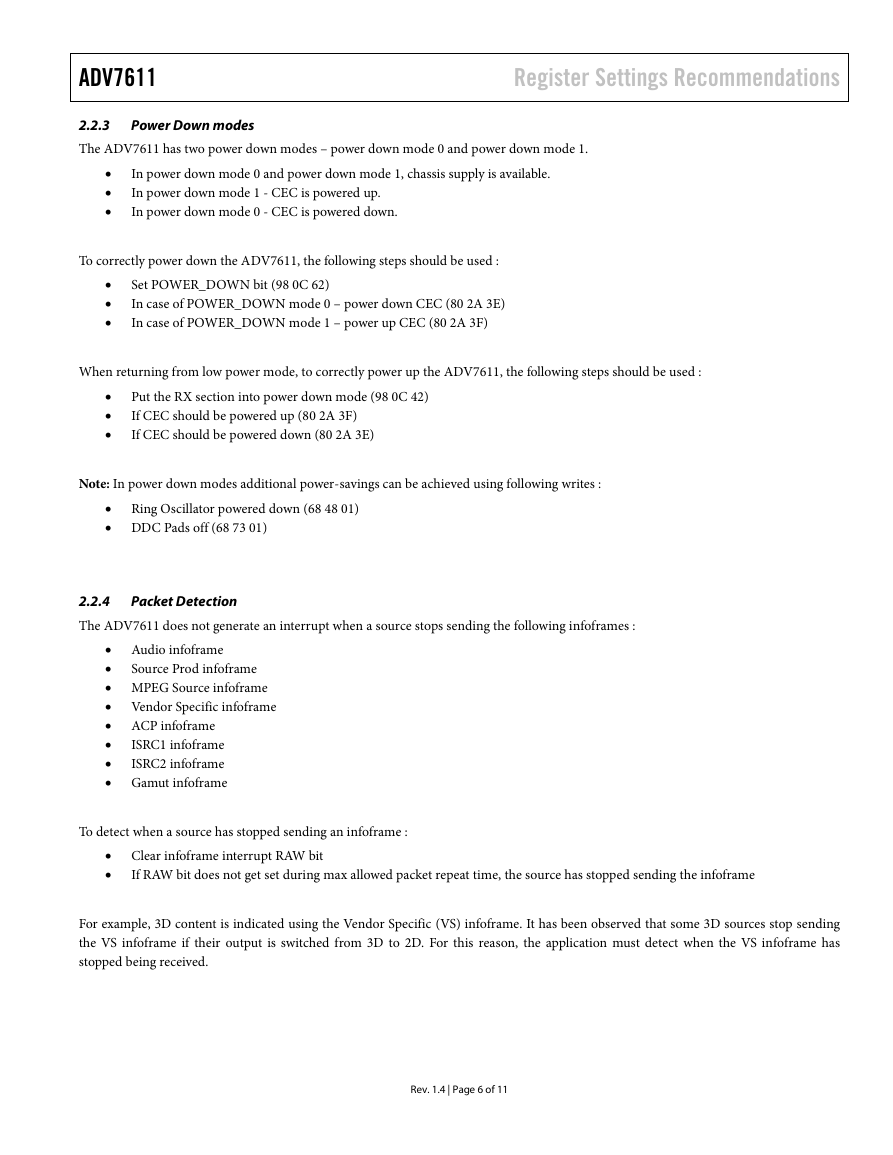
2.2.3
The ADV7611 has two power down modes – power down mode 0 and power down mode 1.
Power Down modes
•
•
•
In power down mode 0 and power down mode 1, chassis supply is available.
In power down mode 1 - CEC is powered up.
In power down mode 0 - CEC is powered down.
To correctly power down the ADV7611, the following steps should be used :
•
•
•
Set POWER_DOWN bit (98 0C 62)
In case of POWER_DOWN mode 0 – power down CEC (80 2A 3E)
In case of POWER_DOWN mode 1 – power up CEC (80 2A 3F)
When returning from low power mode, to correctly power up the ADV7611, the following steps should be used :
•
•
•
Put the RX section into power down mode (98 0C 42)
If CEC should be powered up (80 2A 3F)
If CEC should be powered down (80 2A 3E)
Note: In power down modes additional power-savings can be achieved using following writes :
• Ring Oscillator powered down (68 48 01)
• DDC Pads off (68 73 01)
2.2.4
The ADV7611 does not generate an interrupt when a source stops sending the following infoframes :
Packet Detection
Source Prod infoframe
• Audio infoframe
•
• MPEG Source infoframe
• Vendor Specific infoframe
• ACP infoframe
•
ISRC1 infoframe
•
ISRC2 infoframe
• Gamut infoframe
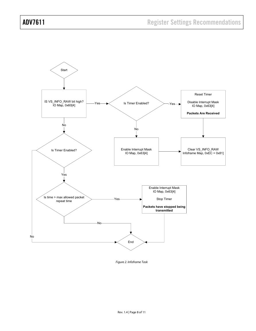
To detect when a source has stopped sending an infoframe :
• Clear infoframe interrupt RAW bit
•
If RAW bit does not get set during max allowed packet repeat time, the source has stopped sending the infoframe
For example, 3D content is indicated using the Vendor Specific (VS) infoframe. It has been observed that some 3D sources stop sending
the VS infoframe if their output is switched from 3D to 2D. For this reason, the application must detect when the VS infoframe has
stopped being received.
Rev. 1.4 | Page 6 of 11
�
ADV7611
Register Settings Recommendations
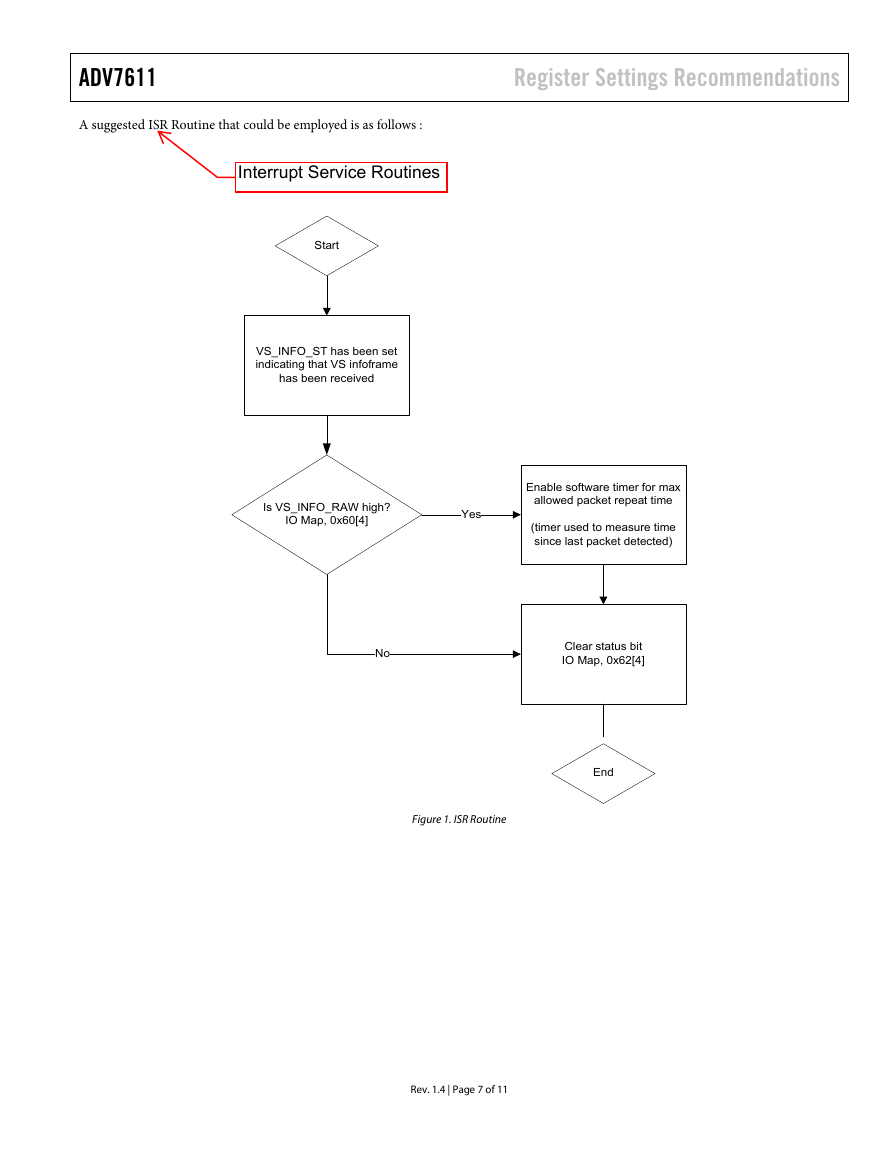
A suggested ISR Routine that could be employed is as follows :
Start
VS_INFO_ST has been set
indicating that VS infoframe
has been received
Is VS_INFO_RAW high?
IO Map, 0x60[4]
Yes
Enable software timer for max
allowed packet repeat time
(timer used to measure time
since last packet detected)
No
Clear status bit
IO Map, 0x62[4]
End
Figure 1. ISR Routine
Rev. 1.4 | Page 7 of 11
�
ADV7611
Register Settings Recommendations
No
Start
IS VS_INFO_RAW bit high?
IO Map, 0x60[4]
Yes
Is Timer Enabled?
Yes
Reset Timer
Disable Interrupt Mask
IO Map, 0x63[4]
Packets Are Received
No
No
Is Timer Enabled?
Enable Interrupt Mask
IO Map, 0x63[4]
Clear VS_INFO_RAW
Infoframe Map, 0xEC = 0x81]
Yes
Is time > max allowed packet
repeat time
Yes
Stop Timer
Enable Interrupt Mask
IO Map, 0x63[4]
Packets have stopped being
transmitted
No
End
Figure 2. Infoframe Task
Rev. 1.4 | Page 8 of 11
�


 2023年江西萍乡中考道德与法治真题及答案.doc
 2012年重庆南川中考生物真题及答案.doc
 2013年江西师范大学地理学综合及文艺理论基础考研真题.doc
 2020年四川甘孜小升初语文真题及答案I卷.doc
 2020年注册岩土工程师专业基础考试真题及答案.doc
 2023-2024学年福建省厦门市九年级上学期数学月考试题及答案.doc
 2021-2022学年辽宁省沈阳市大东区九年级上学期语文期末试题及答案.doc
 2022-2023学年北京东城区初三第一学期物理期末试卷及答案.doc
 2018上半年江西教师资格初中地理学科知识与教学能力真题及答案.doc
 2012年河北国家公务员申论考试真题及答案-省级.doc
 2020-2021学年江苏省扬州市江都区邵樊片九年级上学期数学第一次质量检测试题及答案.doc
 2022下半年黑龙江教师资格证中学综合素质真题及答案.doc