Mechanical Simulation
912 North Main, Suite 210, Ann Arbor MI, 48104, USA
Phone: 734 668-2930 • Fax: 734 668-2877 • Email: info@carsim.com
Technical Memo
www.carsim.com
Running a VS Vehicle Model in Simulink
This memo describes how a VehicleSim (VS) model from a product such as CarSim or TruckSim
runs within a Simulink model. A simple antilock brake system (ABS) example is used that is
installed in TruckSim 7.0. Similar examples are installed in BikeSim and CarSim.
This memo is not intended for specialists in ABS or brake system model, and does not go into
detail about the brake system aspects of the Simulink model. Rather, the point is to show how you
set up a VS vehicle model to work in the Simulink environment.
Locating the Simulink ABS Example
The example for this memo is a Simulink ABS model that is used for a few vehicles and
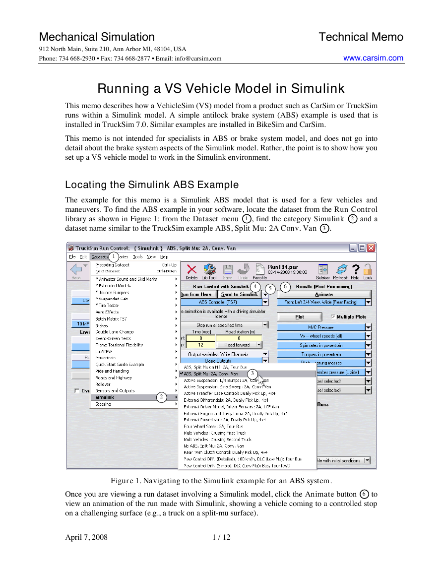
maneuvers. To find the ABS example in your software, locate the dataset from the Run Control
library as shown in Figure 1: from the Dataset menu 1 , find the category Simulink 2 and a
dataset name similar to the TruckSim example ABS, Split Mu: 2A Conv. Van 3 .
1
4
5
6
3
2
Figure 1. Navigating to the Simulink example for an ABS system.
Once you are viewing a run dataset involving a Simulink model, click the Animate button 6 to
view an animation of the run made with Simulink, showing a vehicle coming to a controlled stop
on a challenging surface (e.g., a truck on a split-mu surface).
April 7, 2008
1 / 12
�
Viewing an Existing Run Without Simulink (CarSim, BikeSim 1)
Before looking at the Simulink model, consider the behavior of the vehicle without Simulink. In
VS products prior to CarSim 7 (released in mid-2007), it was necessary to disable subsystem
portions of the vehicle model that were to be handled in Simulink. In the case of the vehicle with
the ABS model defined in Simulink, two vehicles datasets were included in CarSim as examples
with and without ABS. CarSim 7.0 was also released with two versions of an example vehicle.
An example with a Simulink ABS system is in the category Simulink, and dataset name ABS:
Split Mu: B-Class, Hatchback. A run made with the same vehicle with a non-ABS system is in
the category Brakes and dataset name Braking – Split Mu: B-Class, Hatch., No ABS. Navigate
to this run and click the Animate button to see the same vehicle on the same surface, with
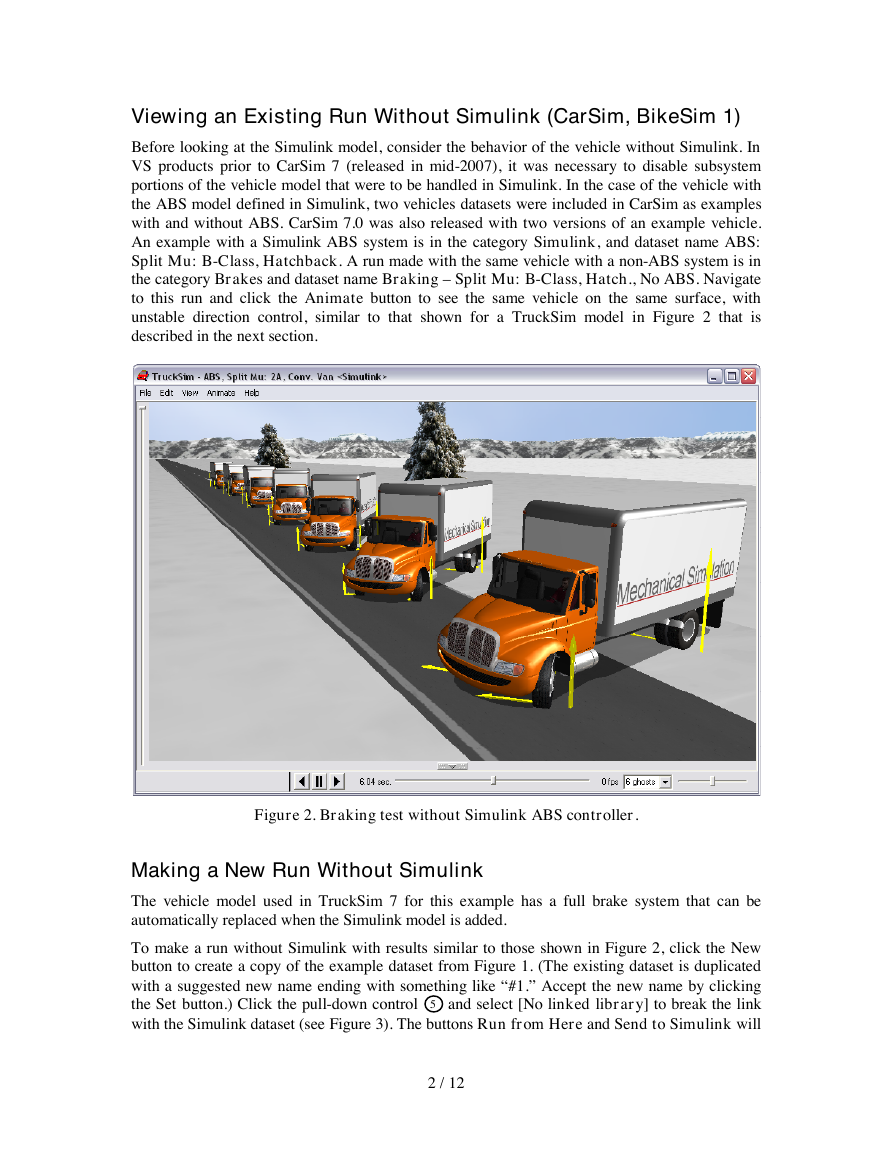
unstable direction control, similar to that shown for a TruckSim model in Figure 2 that is
described in the next section.
Figure 2. Braking test without Simulink ABS controller.
Making a New Run Without Simulink
The vehicle model used in TruckSim 7 for this example has a full brake system that can be
automatically replaced when the Simulink model is added.
To make a run without Simulink with results similar to those shown in Figure 2, click the New
button to create a copy of the example dataset from Figure 1. (The existing dataset is duplicated
with a suggested new name ending with something like “#1.” Accept the new name by clicking
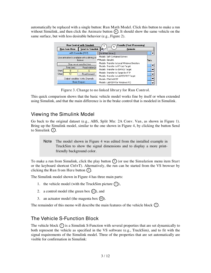
the Set button.) Click the pull-down control 5 and select [No linked library] to break the link
with the Simulink dataset (see Figure 3). The buttons Run from Here and Send to Simulink will
2 / 12
�
automatically be replaced with a single button: Run Math Model. Click this button to make a run
without Simulink, and then click the Animate button 6 . It should show the same vehicle on the
same surface, but with less desirable behavior (e.g., Figure 2).
5
6
Figure 3. Change to no linked library for Run Control.
This quick comparison shows that the basic vehicle model works fine by itself or when extended
using Simulink, and that the main difference is in the brake control that is modeled in Simulink.
Viewing the Simulink Model
Go back to the original dataset (e.g., ABS, Split Mu: 2A Conv. Van, as shown in Figure 1).
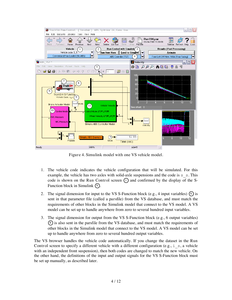
Bring up the Simulink model, similar to the one shown in Figure 4, by clicking the button Send
to Simulink 3 .
Note The model shown in Figure 4 was edited from the installed example in
TruckSim to show the signal dimensions and to display a more print-
friendly background color.
To make a run from Simulink, click the play button 5 (or use the Simulation menu item Start
or the keyboard shortcut Ctrl+T). Alternatively, the run can be started from the VS browser by
clicking the Run from Here button 2 .
The Simulink model shown in Figure 4 has three main parts:
the vehicle model (with the TruckSim picture 7 ),
1.
2. a control model (the green box 11 ), and
3. an actuator model (the magenta box 10 ).
The remainder of this memo will describe the main features of the vehicle block 7 .
The Vehicle S-Function Block
The vehicle block 7 is a Simulink S-Function with several properties that are set dynamically to
both represent the vehicle as specified in the VS software (e.g., TruckSim), and to fit with the
signal requirements of the Simulink model. Three of the properties that are set automatically are
visible for confirmation in Simulink:
3 / 12
�
3
4
1
8
9
2
5
11
7
6
10
Figure 4. Simulink model with one VS vehicle model.
1. The vehicle code indicates the vehicle configuration that will be simulated. For this
example, the vehicle has two axles with solid-axle suspensions and the code is s_s. This
code is shown on the Run Control screen 1 and confirmed by the display of the S-
Function block in Simulink 9 .
2. The signal dimension for input to the VS S-Function block (e.g., 4 input variables) 6 is
sent in that parameter file (called a parsfile) from the VS database, and must match the
requirements of other blocks in the Simulink model that connect to the VS model. A VS
model can be set up to handle anywhere from zero to several hundred input variables.
3. The signal dimension for output from the VS S-Function block (e.g., 6 output variables)
8 is also sent in the parsfile from the VS database, and must match the requirements of
other blocks in the Simulink model that connect to the VS model. A VS model can be set
up to handle anywhere from zero to several hundred output variables.
The VS browser handles the vehicle code automatically. If you change the dataset in the Run
Control screen to specify a different vehicle with a different configuration (e.g., i_s, a vehicle
with an independent front suspension), then both codes are changed to match the new vehicle. On
the other hand, the definitions of the input and output signals for the VS S-Function block must
be set up manually, as described later.
4 / 12
�
Note
If you change the vehicle, its properties, or the sets of import or export
variables from the VS browser, you must click the Send to Simulink
button 4 to update the model in Simulink.
Simulink Configuration Parameters
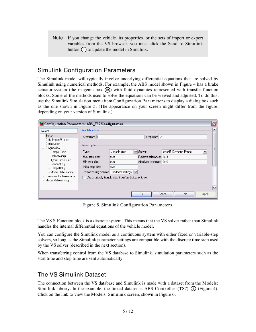
The Simulink model will typically involve underlying differential equations that are solved by
Simulink using numerical methods. For example, the ABS model shown in Figure 4 has a brake
actuator system (the magenta box 10 ) with fluid dynamics represented with transfer function
blocks. Some of the methods used to solve the equations can be viewed and adjusted. To do this,
use the Simulink Simulation menu item Configuration Parameters to display a dialog box such
as the one shown in Figure 5. (The appearance on your screen might differ from the figure,
depending on your version of Simulink.)
Figure 5. Simulink Configuration Parameters.
The VS S-Function block is a discrete system. This means that the VS solver rather than Simulink
handles the internal differential equations of the vehicle model.
You can configure the Simulink model as a continuous system with either fixed or variable-step
solvers, so long as the Simulink parameter settings are compatible with the discrete time step used
by the VS solver (described in the next section).
When transferring control from the VS database to Simulink, simulation parameters such as the
start time and stop time are sent automatically.
The VS Simulink Dataset
The connection between the VS database and Simulink is made with a dataset from the Models:
Simulink library. In the example, the linked dataset is ABS Controller (TS7) 4 (Figure 4).
Click on the link to view the Models: Simulink screen, shown in Figure 6.
5 / 12
�
2
3
1
4
5
Figure 6. Models Simulink dataset for the ABS controller.
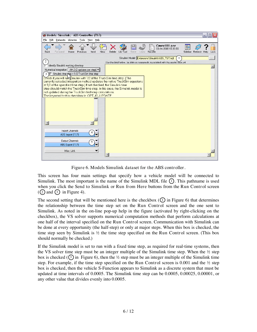
This screen has four main settings that specify how a vehicle model will be connected to
Simulink. The most important is the name of the Simulink MDL file 1 . This pathname is used
when you click the Send to Simulink or Run from Here buttons from the Run Control screen
( 2 and 3 in Figure 4).
The second setting that will be mentioned here is the checkbox ( 3 in Figure 6) that determines
the relationship between the time step set on the Run Control screen and the one sent to
Simulink. As noted in the on-line pop-up help in the figure (activated by right-clicking on the
checkbox), the VS solver supports numerical computation methods that perform calculations at
one half of the interval specified on the Run Control screen. Communication with Simulink can
be done at every opportunity (the half-step) or only at major steps. When this box is checked, the
time step seen by Simulink is ½ the time step specified on the Run Control screen. (This box
should normally be checked.)
If the Simulink model is set to run with a fixed time step, as required for real-time systems, then
the VS solver time step must be an integer multiple of the Simulink time step. When the ½ step
box is checked ( 3 in Figure 6), then the ½ step must be an integer multiple of the Simulink time
step. For example, if the time step specified on the Run Control screen is 0.001 and the ½ step
box is checked, then the vehicle S-Function appears to Simulink as a discrete system that must be
updated at time intervals of 0.0005. The Simulink time step can be 0.0005, 0.00025, 0.00001, or
any other value that divides evenly into 0.0005.
6 / 12
�
Note For more information about the numerical integration methods used by
the VS solver programs, see the VehicleSim Solver Program Reference
Manual.
The third and fourth settings on this screen are links to datasets that define the sets of variables
that will be activated for import into the VS model 4 and those activated for export out from the
model 5 .
Although it is not used for this example, the checkbox 2 is available for Simulink users who
want to run the vehicle models under full control of Simulink. In those cases, the MDL file is
loaded outside the control of the VS browser and the current working directory is set according to
how the Simulink environment is started. To support this type of operation, the box would be
checked and another data field is displayed to identify the working directory, where the VS solver
will send data files needed by the VS S-Function block.
Import Variables
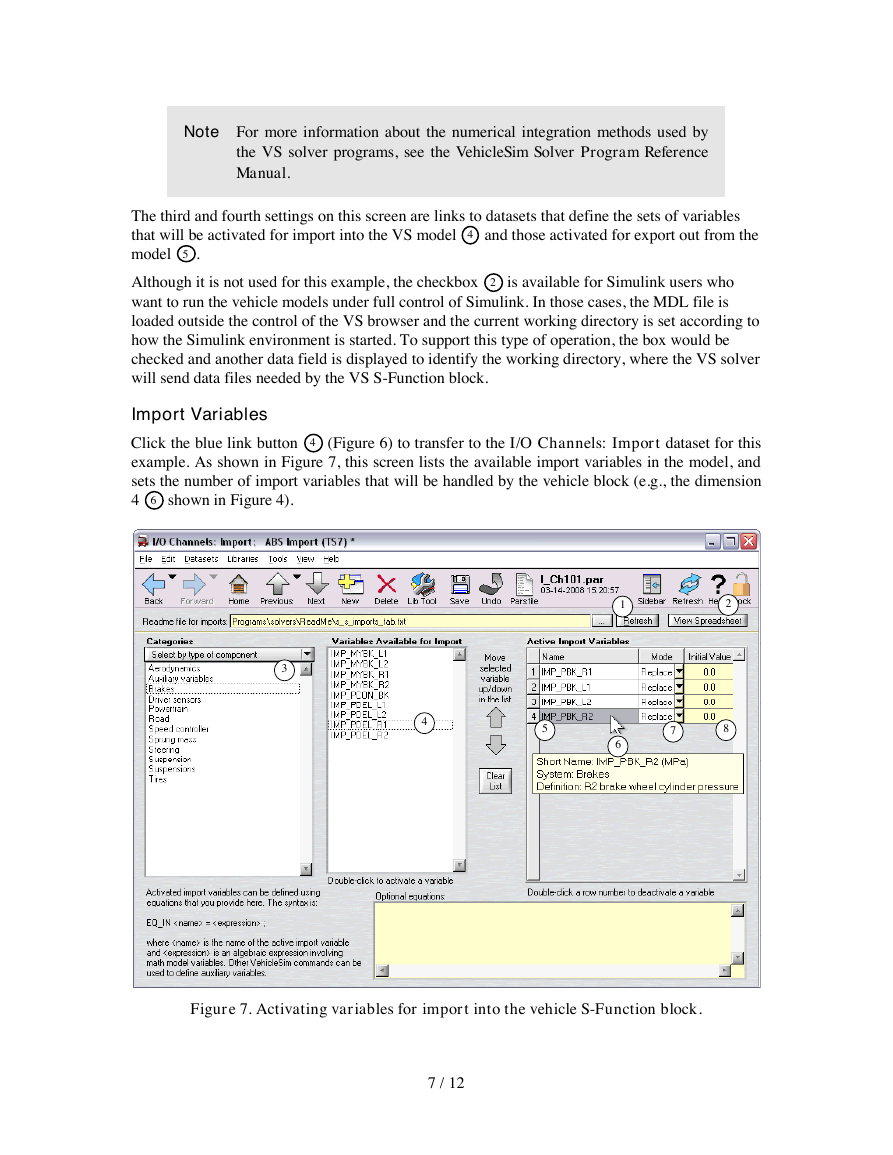
Click the blue link button 4 (Figure 6) to transfer to the I/O Channels: Import dataset for this
example. As shown in Figure 7, this screen lists the available import variables in the model, and
sets the number of import variables that will be handled by the vehicle block (e.g., the dimension
4 6 shown in Figure 4).
3
4
5
1
6
2
7
8
Figure 7. Activating variables for import into the vehicle S-Function block.
7 / 12
�
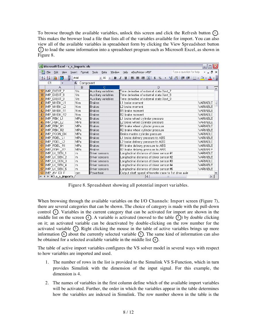
To browse through the available variables, unlock this screen and click the Refresh button 1 .
This makes the browser load a file that lists all of the variables available for import. You can also
view all of the available variables in spreadsheet form by clicking the View Spreadsheet button
2 to load the same information into a spreadsheet program such as Microsoft Excel, as shown in
Figure 8.
Figure 8. Spreadsheet showing all potential import variables.
When browsing through the available variables on the I/O Channels: Import screen (Figure 7),
there are several categories that can be shown. The choice of category is made with the pull-down
control 3 . Variables in the current category that can be activated for import are shown in the
middle list on the screen 4 . A variable is activated (moved to the table 5 ) by double clicking
on it; an activated variable can be deactivated by double-clicking on the row number for the
activated variable 5 . Right clicking the mouse in the table of active variables brings up more
information 6 about the currently selected variable 5 . The same kind of information can also
be obtained for a selected available variable in the middle list 4 .
The table of active import variables configures the VS solver model in several ways with respect
to how variables are imported and used.
1. The number of rows in the list is provided to the Simulink VS S-Function, which in turn
provides Simulink with the dimension of the input signal. For this example, the
dimension is 4.
2. The names of variables in the first column define which of the available import variables
will be activated. Further, the order in which the variables appear in the table determines
how the variables are indexed in Simulink. The row number shown in the table is the
8 / 12
�


 2023年江西萍乡中考道德与法治真题及答案.doc
 2012年重庆南川中考生物真题及答案.doc
 2013年江西师范大学地理学综合及文艺理论基础考研真题.doc
 2020年四川甘孜小升初语文真题及答案I卷.doc
 2020年注册岩土工程师专业基础考试真题及答案.doc
 2023-2024学年福建省厦门市九年级上学期数学月考试题及答案.doc
 2021-2022学年辽宁省沈阳市大东区九年级上学期语文期末试题及答案.doc
 2022-2023学年北京东城区初三第一学期物理期末试卷及答案.doc
 2018上半年江西教师资格初中地理学科知识与教学能力真题及答案.doc
 2012年河北国家公务员申论考试真题及答案-省级.doc
 2020-2021学年江苏省扬州市江都区邵樊片九年级上学期数学第一次质量检测试题及答案.doc
 2022下半年黑龙江教师资格证中学综合素质真题及答案.doc