Schematic Capture
Training Module
�
Document Version 1.01, December 4, 2006
Software, documentation and related materials:
Copyright © 2006 Altium Limited.
All rights reserved. You are permitted to print this document provided that (1) the use of such is
for personal use only and will not be copied or posted on any network computer or broadcast in
any media, and (2) no modifications of the document is made. Unauthorized duplication, in whole
or part, of this document by any means, mechanical or electronic, including translation into
another language, except for brief excerpts in published reviews, is prohibited without the express
written permission of Altium Limited. Unauthorized duplication of this work may also be prohibited
by local statute. Violators may be subject to both criminal and civil penalties, including fines
and/or imprisonment.
Altium, Altium Designer, Board Insight, CAMtastic, CircuitStudio, Design Explorer, DXP,
LiveDesign, NanoBoard, NanoTalk, Nexar, nVisage, P-CAD, Protel, SimCode, Situs, TASKING,
and Topological Autorouting and their respective logos are trademarks or registered trademarks
of Altium Limited or its subsidiaries.
Microsoft, Microsoft Windows and Microsoft Access are registered trademarks of Microsoft
Corporation. OrCAD, OrCAD Capture, OrCAD Layout and SPECCTRA are registered trademarks
of Cadence Design Systems Inc. AutoCAD is a registered trademark of AutoDesk Inc. HP-GL is a
registered trademark of Hewlett Packard Corporation. PostScript is a registered trademark of
Adobe Systems, Inc. All other registered or unregistered trademarks referenced herein are the
property of their respective owners and no trademark rights to the same are claimed.
Schematic Capture Training Module
ii
�
Schematic Capture Training Module
4.
3.
1.
2.
Introduction to Schematic Capture .........................................................................3-1
The Schematic Editor workspace............................................................................3-2
2.1
Document Options..........................................................................................3-2
2.2
Preferences ....................................................................................................3-8
Libraries and components .....................................................................................3-21
Locating and loading libraries ......................................................................3-21
3.1
3.2
Locating components ...................................................................................3-22
Browsing libraries .........................................................................................3-23
3.3
3.4
Exercises – Libraries and components ........................................................3-24
Placing and wiring ..................................................................................................3-26
Placing components.....................................................................................3-26
4.1
Pin-to-pin wiring............................................................................................3-26
4.2
Exercise – Drawing the schematic ...............................................................3-27
4.3
4.4
Exercise – Setting the component’s footprint value .....................................3-29
Exercise – Completing the Sensor schematic .............................................3-30
4.5
5. Multi-Sheet Design..................................................................................................3-31
Structuring a multi-sheet design...................................................................3-31
5.1
Multi-sheet design connectivity ....................................................................3-32
5.2
Constructing the top sheet ...........................................................................3-33
5.3
Assigning the sheet numbers and total number of sheets...........................3-35
5.4
Checking sheet symbol to sub-sheet synchronization.................................3-36
5.5
Assigning designators ...........................................................................................3-37
Using Annotate to assign designators..........................................................3-37
6.1
6.2
Designators on multi-part components ........................................................3-38
6.3
Exercise – Annotating the design.................................................................3-38
Compiling and verifying the project......................................................................3-39
7.1
Setting up to compile the design ..................................................................3-39
7.2
Interpreting the messages and locating the errors.......................................3-41
Editing Multiple Text Objects.................................................................................3-42
8.1
Find and Replace Text .................................................................................3-42
Interfacing to other design tools ...........................................................................3-43
Setting the relevant project options..............................................................3-43
9.1
Transferring a design to the PCB Editor ......................................................3-43
9.2
Netlist formats ..............................................................................................3-44
9.3
9.4
Exercise – setting project options for design transfer ..................................3-44
10. Parameters...............................................................................................................3-45
10.1
The Parameter Manager ..............................................................................3-46
10.2 Exercises – Using the Parameter Manager .................................................3-48
11. Reports.....................................................................................................................3-49
11.1 Schematic Editor reports..............................................................................3-49
12. Printing.....................................................................................................................3-51
12.1 Setting up and printing .................................................................................3-51
6.
7.
8.
9.
Schematic Capture Training Module
iii
�
1. Introduction to Schematic Capture
The Schematic Capture training session covers how to create single sheet schematics and multi-
sheet hierarchical projects from initial setup through to component placement, wiring, design
verification and printing. The functionality of the Schematic Editor will be explored and a series of
exercises will show you how to capture a design as a schematic, ready for PCB design.
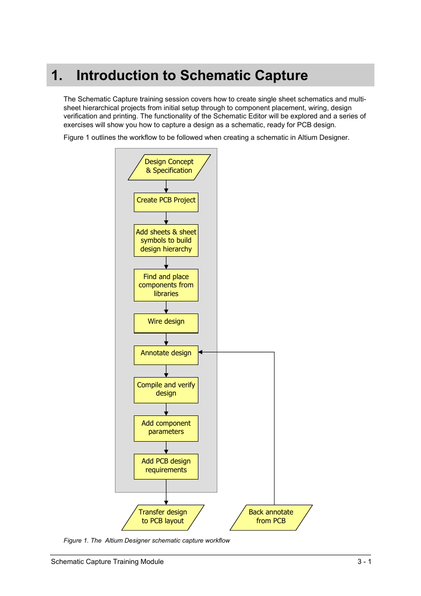
Figure 1 outlines the workflow to be followed when creating a schematic in Altium Designer.
Design Concept
& Specification
Create PCB Project
Add sheets & sheet
symbols to build
design hierarchy
Find and place
components from
libraries
Wire design
Annotate design
Compile and verify
design
Add component
parameters
Add PCB design
requirements
Transfer design
to PCB layout
Back annotate
from PCB
Figure 1. The Altium Designer schematic capture workflow
Schematic Capture Training Module
3 - 1
�
2. The Schematic Editor workspace
This section describes how to set up and browse the Schematic Editor workspace, done via the
Document Options and Preferences dialogs. Sheet options, such as grids and templates, as well
as preferences and defaults can be set through these dialogs.
To open the Schematic Editor, simply create a new schematic document (File » New »
Schematic) or open an existing .SchDoc document in Altium Designer.
2.1
Document Options
The Document Options dialog allows you to:
• Set parameters relating to individual schematic files.
• The settings in this dialog are saved with that schematic file.
• The Document Options dialog is displayed by double-clicking on the sheet border, or by
choosing the Design » Options menu command.
The tabs of the Document Options dialog are described in the following sections.
2.1.1
Sheet Options tab
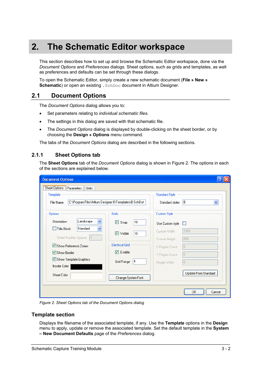
The Sheet Options tab of the Document Options dialog is shown in Figure 2. The options in each
of the sections are explained below.
Figure 2. Sheet Options tab of the Document Options dialog
Template section
Displays the filename of the associated template, if any. Use the Template options in the Design
menu to apply, update or remove the associated template. Set the default template in the System
– New Document Defaults page of the Preferences dialog.
Schematic Capture Training Module
3 - 2
�
Options section
Orientation
Sets the sheet orientation to Landscape or Portrait.
Title Block
When checked, a standard title block is attached to the sheet. The format of that title block is set
using the drop-down list next to this option. Note that this is typically only used when there is no
associated template.
Show Reference Zones
When checked, the sheet has a reference grid defined in its border.
Show Border
When checked the sheet border is displayed.
Show Template Graphics
When checked, any objects placed in the template file defined for the sheet will be displayed in
the sheet. This is typically used to display a non-standard title block, in which case you would
uncheck the Title Block option.
Border Color
Allows you to set the border color from the Choose Color dialog.
Sheet Color
Allows you to set the background color of the sheet.
Standard Style section
Allows you to select the size of the sheet from a number of standard sizes e.g. A4, A3.
Custom Style section
Allows you to define a custom sheet size and border. Use this option if you want a sheet size not
covered in the Standard Style section.
Change System Font
This button allows you to change the font used to display pin numbers, pin names, port text,
power port text and sheet border text.
Grids section
Grids Options allow you to set the size and turn on or off the Snap Grid and the Visible Grid.
SnapOn
The Snap Grid forces the mouse click location to the closest snap grid point. The Snap Grid is set
and can be turned on or off in the Document Options dialog. You can also cycle though three
predefined grids by pressing the G shortcut key at any time.
Visible
The Visible Grid displays a grid when turned on. This is independent of the Snap Grid. The Visible
Grid can also be turned on or off in the View menu (VV).
Schematic Capture Training Module
3 - 3
�
Electrical Grid section
The Electrical Grid can be turned on or off and the Electrical Grid Range can be set in the
Document Options dialog. It can also be turned on or off in the View menu (VE).
When the Electrical Grid is turned on and you are executing a command that supports the
electrical grid, the cursor overrides the Snap Grid and jumps to key points on objects.
For example, if you are using the Place » Wire command and move the cursor to a certain
distance within the Electrical Grid Range of a pin, the cursor will jump to the pin.
2.1.2
Parameters tab
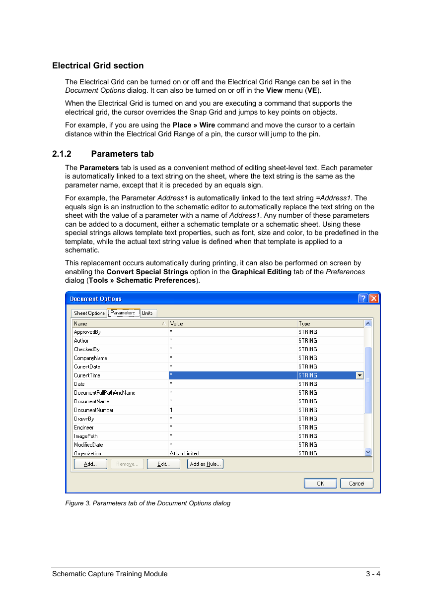
The Parameters tab is used as a convenient method of editing sheet-level text. Each parameter
is automatically linked to a text string on the sheet, where the text string is the same as the
parameter name, except that it is preceded by an equals sign.
For example, the Parameter Address1 is automatically linked to the text string =Address1. The
equals sign is an instruction to the schematic editor to automatically replace the text string on the
sheet with the value of a parameter with a name of Address1. Any number of these parameters
can be added to a document, either a schematic template or a schematic sheet. Using these
special strings allows template text properties, such as font, size and color, to be predefined in the
template, while the actual text string value is defined when that template is applied to a
schematic.
This replacement occurs automatically during printing, it can also be performed on screen by
enabling the Convert Special Strings option in the Graphical Editing tab of the Preferences
dialog (Tools » Schematic Preferences).
Figure 3. Parameters tab of the Document Options dialog
Schematic Capture Training Module
3 - 4
�
The default special strings are listed in the table below, but you can create custom parameters to
suit your document and design requirements.
Special String
=Address1
=Address2
=Address3
=Address4
=ApprovedBy
=Author
Description
Line of an address
Line of an address
Line of an address
Line of an address
Approver’s name
Author’s name
=Checked By
=CompanyName
Checker’s name
Company name
=CurrentDate
=CurrentTime
=Date
=DocumentFullPath
AndName
=DocumentName
Computer system date
(value entered automatically)
Computer system time
(value entered automatically)
Date (not automatically
updated)
Filename with full path of the
schematic sheet (value
entered automatically)
Filename without the path
(value entered automatically)
=DocumentNumber
=DrawnBy
Document number
Draftsperson’s name
Special String
=Engineer
=ImagePath
=Modified Date
=Organization
=Revision
=Rule
=SheetNumber
=SheetTotal
=Time
=Title
Description
Engineer’s name
Path to image file
Computer system date of
last modification to file (value
entered automatically)
Organization name
Revision number
Rule description if added
using Add as Rule option
Schematic sheet number
Total number of sheets in
the project
Time (not automatically
updated)
Title of schematic sheet
=Engineer
Engineer’s name
=ImagePath
Path to image file
=Modified Date
Computer system date of
last modification to file (value
entered automatically)
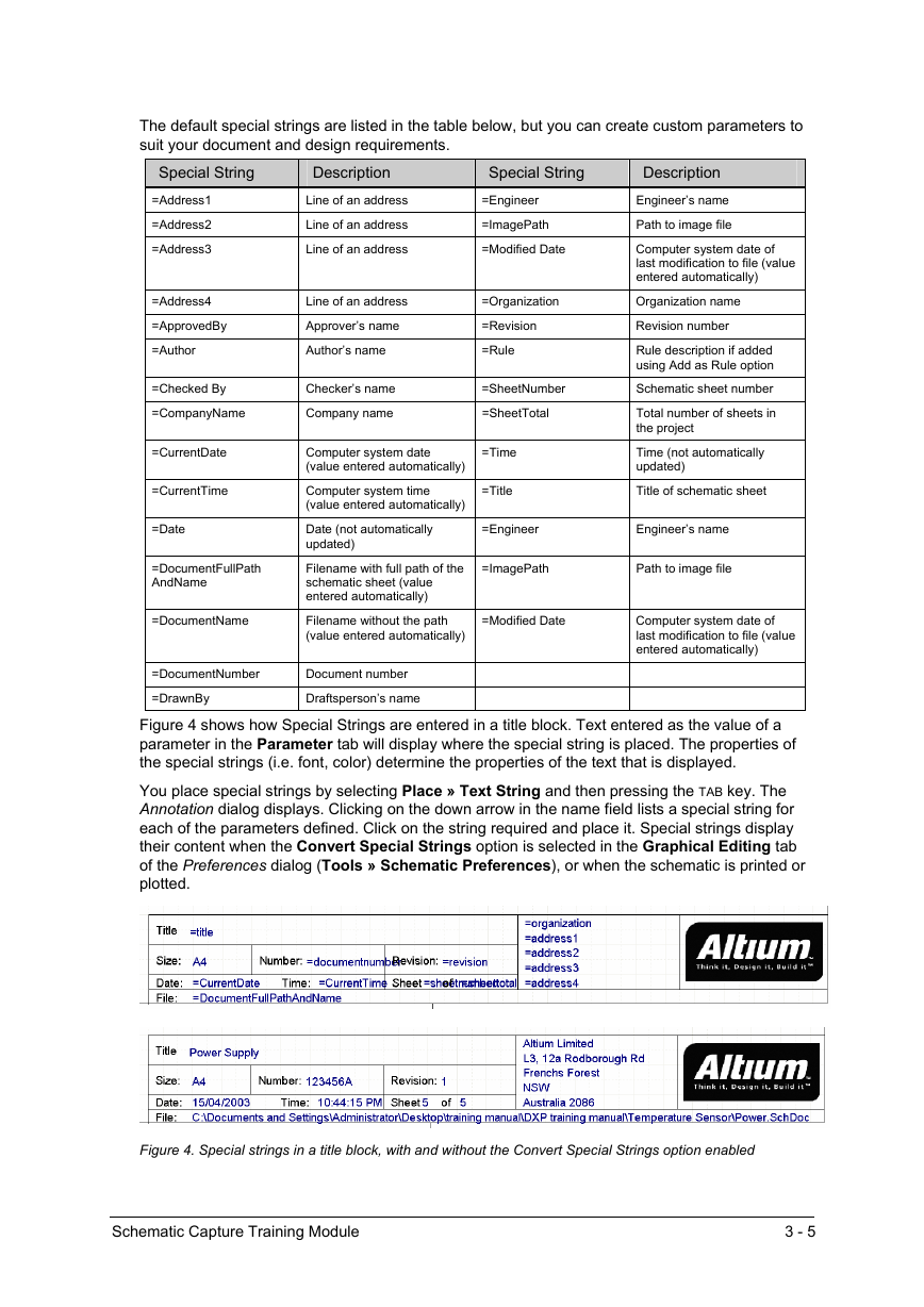
Figure 4 shows how Special Strings are entered in a title block. Text entered as the value of a
parameter in the Parameter tab will display where the special string is placed. The properties of
the special strings (i.e. font, color) determine the properties of the text that is displayed.
You place special strings by selecting Place » Text String and then pressing the TAB key. The
Annotation dialog displays. Clicking on the down arrow in the name field lists a special string for
each of the parameters defined. Click on the string required and place it. Special strings display
their content when the Convert Special Strings option is selected in the Graphical Editing tab
of the Preferences dialog (Tools » Schematic Preferences), or when the schematic is printed or
plotted.
Figure 4. Special strings in a title block, with and without the Convert Special Strings option enabled
Schematic Capture Training Module
3 - 5
�





 2023年江西萍乡中考道德与法治真题及答案.doc
 2012年重庆南川中考生物真题及答案.doc
 2013年江西师范大学地理学综合及文艺理论基础考研真题.doc
 2020年四川甘孜小升初语文真题及答案I卷.doc
 2020年注册岩土工程师专业基础考试真题及答案.doc
 2023-2024学年福建省厦门市九年级上学期数学月考试题及答案.doc
 2021-2022学年辽宁省沈阳市大东区九年级上学期语文期末试题及答案.doc
 2022-2023学年北京东城区初三第一学期物理期末试卷及答案.doc
 2018上半年江西教师资格初中地理学科知识与教学能力真题及答案.doc
 2012年河北国家公务员申论考试真题及答案-省级.doc
 2020-2021学年江苏省扬州市江都区邵樊片九年级上学期数学第一次质量检测试题及答案.doc
 2022下半年黑龙江教师资格证中学综合素质真题及答案.doc