klcd-001
产品说明书
1
�
目录
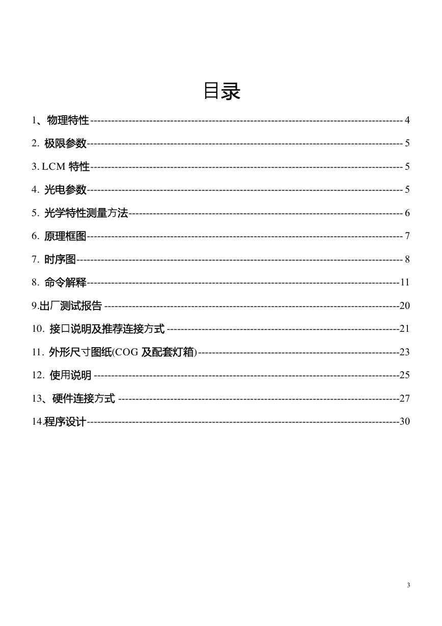
1、物理特性 ------------------------------------------------------------------------------------------ 4
2. 极限参数------------------------------------------------------------------------------------------- 5
3. LCM 特性------------------------------------------------------------------------------------------ 5
4. 光电参数------------------------------------------------------------------------------------------- 5
5. 光学特性测量方法------------------------------------------------------------------------------- 6
6. 原理框图------------------------------------------------------------------------------------------- 7
7. 时序图---------------------------------------------------------------------------------------------- 8
8. 命令解释------------------------------------------------------------------------------------------11
9.出厂测试报告 -------------------------------------------------------------------------------------20
10. 接口说明及推荐连接方式 -------------------------------------------------------------------21
11. 外形尺寸图纸(COG 及配套灯箱)----------------------------------------------------------23
12. 使用说明 ----------------------------------------------------------------------------------------25
13、硬件连接方式 ---------------------------------------------------------------------------------27
14.程序设计------------------------------------------------------------------------------------------30
3
�
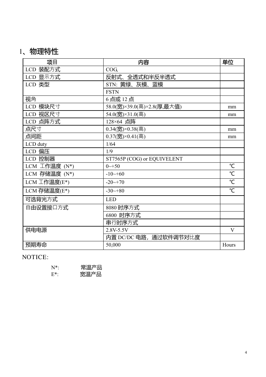
内容
COG,
反射式、全透式和半反半透式
STN: 黄绿、灰模、蓝模
FSTN
6 点或 12 点
58.0(宽)×39.0(高)×2.8(厚,最大值)
54.0(宽)×31.0(高)
128×64 点阵
0.34(宽)×0.38(高)
0.37(宽)×0.41(高)
1/64
1/9
ST7565P (COG) or EQUIVELENT
0~+50
-10~+60
-20~+70
-30~+80
LED
8080 时序方式
6800 时序方式
串行时序方式
2.8V-5.5V
内置 DC/DC 电路,通过软件调节对比度
50,000
1、物理特性
项目
LCD 装配方式
LCD 显示方式
LCD 类型
视角
LCD 模块尺寸
LCD 视区尺寸
LCD 点阵方式
点尺寸
点间距
LCD duty
LCD 偏压
LCD 控制器
LCM 工作温度 (N*)
LCM 存储温度 (N*)
LCM 工作温度(E*)
LCM 存储温度(E*)
可选背光方式
自由设置接口方式
供电电源
预期寿命
NOTICE:
N*: 常温产品
E*: 宽温产品
单位
mm
mm
mm
mm
℃
℃
℃
℃
V
Hours
4
�
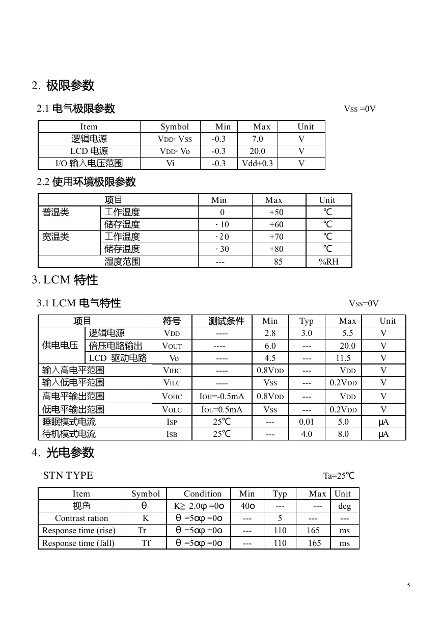
2. 极限参数
2.1 电气极限参数
Item
逻辑电源
LCD 电源
Symbol
VDD-VSS
VDD-Vo
I/O 输入电压范围
Vi
2.2 使用环境极限参数
项目
普温类
工作温度
储存温度
工作温度
储存温度
湿度范围
宽温类
VSS =0V
Max
7.0
20.0
Vdd+0.3
Unit
V
V
V
Max
+50
+60
+70
+80
85
Unit
℃
℃
℃
℃
%RH
Min
-0.3
-0.3
-0.3
Min
0
-10
-20
-30
---
3. LCM 特性
3.1 LCM 电气特性
项目
供电电压
逻辑电源
倍压电路输出
LCD 驱动电路
输入高电平范围
输入低电平范围
高电平输出范围
低电平输出范围
睡眠模式电流
待机模式电流
4. 光电参数
符号
VDD
VOUT
Vo
VIHC
VILC
VOHC
VOLC
ISP
ISB
----
----
----
----
----
VSS=0V
Unit
V
V
V
V
V
V
V
μA
μA
测试条件 Min
2.8
6.0
4.5
0.8VDD
VSS
0.8VDD
VSS
---
---
Max
5.5
20.0
11.5
VDD
0.2VDD
VDD
0.2VDD
Typ
3.0
---
---
---
---
---
---
0.01
4.0
IOH=-0.5mA
IOL=0.5mA
25℃
25℃
5.0
8.0
STN TYPE Ta=25℃
Item
视角
Contrast ration
Response time (rise)
Response time (fall)
Symbol
θ
K
Tr
Tf
Condition Min
40o
---
---
---
K≧2.0φ=0o
θ=5oφ=0o
θ=5oφ=0o
θ=5oφ=0o
Typ
---
5
110
110
Max Unit
---
deg
---
---
ms
165
165
ms
5
�
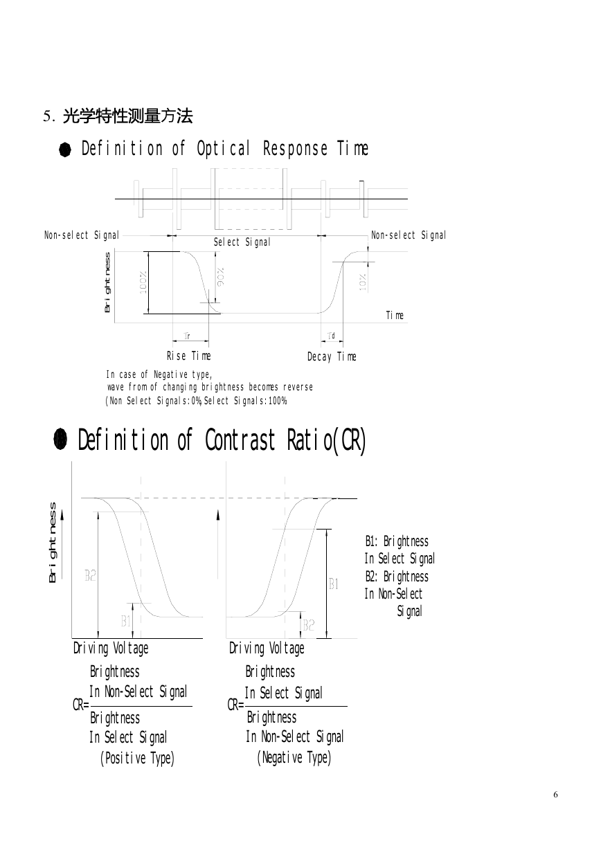
5. 光学特性测量方法
Definition of Optical Response Time
Non-select Signal
Select Signal
Non-select Signal
s
s
e
n
t
h
g
i
r
B
r
Rise Time
d
Decay Time
In case of Negative type,
wave from of changing brightness becomes reverse
(Non Select Signals:0%,Select Signals:100%
Definition of Contrast Ratio(CR)
Time
s
s
e
n
t
h
g
i
r
B
B1: Brightness
In Select Signal
B2: Brightness
In Non-Select
Signal
Driving Voltage
Driving Voltage
Brightness
In Non-Select Signal
CR=
Brightness
In Select Signal
(Positive Type)
CR=
Brightness
In Select Signal
Brightness
In Non-Select Signal
(Negative Type)
6
�
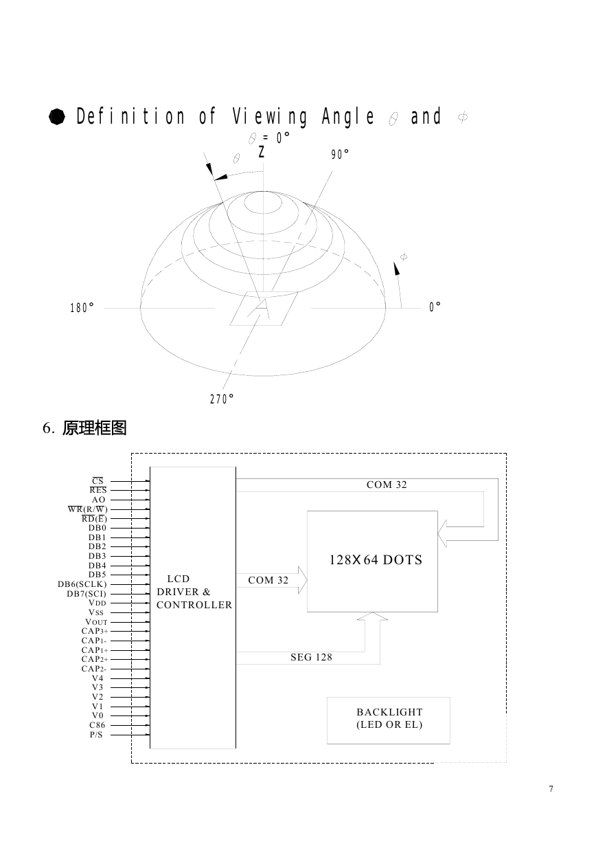
Definition of Viewing Angle and
0°
=
z
90°
180°
0°
270°
6. 原理框图
CS
RES
AO
WR(R/W)
RD(E)
DB0
DB1
DB2
DB3
DB4
DB5
DB6(SCLK)
DB7(SCI)
VDD
VSS
VOUT
CAP3+
CAP1-
CAP1+
CAP2+
CAP2-
V4
V3
V2
V1
V0
C86
P/S
LCD
DRIVER &
CONTROLLER
COM 32
COM 32
128X64 DOTS
SEG 128
BACKLIGHT
(LED OR EL)
7
�
7. 时序图
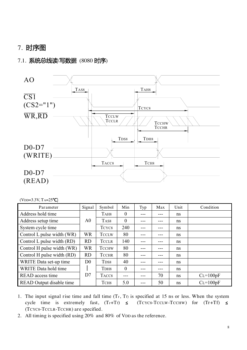
7.1. 系统总线读/写数据 (8080 时序)
AO
CS1
(CS2="1")
WR,RD
D0-D7
(WRITE)
D0-D7
(READ)
TAS8
TAH8
TCYC8
TCCLW
TCCLR
TCCHW
TCCHR
TDS8
TDH8
TACC8
TCH8
A0
(VDD=3.3V, TA=25℃)
Parameter
Address hold time
Address setup time
System cycle time
Control L pulse width (WR) WR
Control L pulse width (RD)
RD
Control H pulse width (WR) WR
RD
Control H pulse width (RD)
D0
WRITE Data set-up time
│
WRITE Data hold time
D7
READ access time
READ Output disable time
1. The input signal rise time and fall time (Tr, Tf) is specified at 15 ns or less. When the system
(Tr+Tf) ≤
Signal Symbol
TAH8
TAS8
TCYC8
TCCLW
TCCLR
TCCHW
TCCHR
TDS8
TDH8
TACC8
TCH8
Max
---
---
---
---
---
---
---
---
---
70
50
Unit
ns
ns
ns
ns
ns
ns
ns
ns
ns
ns
ns
Min
0
0
240
80
140
80
80
40
0
---
5.0
Typ
---
---
---
---
---
---
---
---
---
---
---
CL=100pF
CL=100pF
(Tr+Tf) ≤
(TCYC8-TCCLW-TCCHW)
for
time
cycle
(TCYC8-TCCLR-TCCHR) are specified.
is extremely
fast,
2. All timing is specified using 20% and 80% of VDD as the reference.
Condition
8
�
3. TCCLW and TCCLR are specified as the overlap between /CS1 being “L” (CS2=“H”) and /WR
and /RD being at the “L” level.
7.2. System buses Read/Write characteristics (For the 6800 Series MPU)
(VDD=3.3V, TA=25℃)
Parameter
Condition
Signal
A0
D0
│
D7
RD
WR
RD
WR
Symbol Min
240
TCYC6
TAS6
0
0
TAH6
40
TDS6
TDH6
0
5
TOH6
---
TACC6
TEWHR
140
80
TEWHW
80
TEWLR
TEWLW
80
System cycle time
Address setup time
Address hold time
WRITE Data set-up time
WRITE Data hold time
READ Output disable time
READ Access time
Enable H pulse width (Read)
Enable H pulse width (Write)
Enable L pulse width (Read)
Enable L pulse width (Write)
1.The input signal rise time and fall time (Tr, Tf) is specified at 15 ns or less. When the system cycle
time is extremely fast, (Tr+Tf) ≤ (TCYC6-TEWLW-TEWHW) for (Tr+Tf) ≤ (TCYC6-TEWLR-TEWHR)
are specified.
2.All timing is specified using 20% and 80% of VDD as the reference.
3.TEWLW and TEWLR are specified as the overlap between /CS1 being “L” (CS2=“H”) and E.
7.3. Serial interface
Max
---
---
---
---
---
50
70
---
---
---
---
Unit
ns
ns
ns
ns
ns
ns
ns
ns
ns
ns
ns
Typ
---
---
---
---
---
---
---
---
---
---
---
CL=100pF
CL=100pF
A O
R /W
C S 1
(C S 2 = " 1 " )
E
D 0 -D 7
(W R IT E )
D 0 -D 7
(R E A D )
T A S 6
T A H 6
T C Y C 6
T E W H W T E W H R
T D S 6
T E W L W T E W L R
T D H 6
T A C C 6
T O H 6
9
�


 2023年江西萍乡中考道德与法治真题及答案.doc
 2012年重庆南川中考生物真题及答案.doc
 2013年江西师范大学地理学综合及文艺理论基础考研真题.doc
 2020年四川甘孜小升初语文真题及答案I卷.doc
 2020年注册岩土工程师专业基础考试真题及答案.doc
 2023-2024学年福建省厦门市九年级上学期数学月考试题及答案.doc
 2021-2022学年辽宁省沈阳市大东区九年级上学期语文期末试题及答案.doc
 2022-2023学年北京东城区初三第一学期物理期末试卷及答案.doc
 2018上半年江西教师资格初中地理学科知识与教学能力真题及答案.doc
 2012年河北国家公务员申论考试真题及答案-省级.doc
 2020-2021学年江苏省扬州市江都区邵樊片九年级上学期数学第一次质量检测试题及答案.doc
 2022下半年黑龙江教师资格证中学综合素质真题及答案.doc