IEEE TRANSACTIONS ON INDUSTRY APPLICATIONS, VOL. 44, NO. 3, MAY/JUNE 2008
777
A New Speed-Varying Ellipse Voltage Injection
Method for Sensorless Drive of Permanent-Magnet
Synchronous Motors With Pole Saliency—New PLL
Method Using High-Frequency Current
Component Multiplied Signal
Shinji Shinnaka, Member, IEEE
Abstract—This paper proposes a new sensorless vector control
method for salient-pole permanent-magnet synchronous motors.
With regard to phase estimation, the sensorless vector control
method is featured by a new high-frequency voltage injection
method (i.e., carrier modulation method), which is distinguished
from the conventional ones by a unique ellipse shape of spatially
rotating high-frequency voltage, and by a new phase-locked-loop
method as a demodulation method whose input is a high-frequency
current component multiplied signal. The new vector control
method established by two innovative technologies for modulation/
demodulation can have the following high-performance and at-
tractive characteristics. 1) It can allow 250% rated torque at
standstill. 2) It can operate from zero to the rated speed under
the rated motoring or regenerating load. 3) It accepts instant
injection of the rated load even for zero-speed control. 4) Phase
estimation is robust against inverter dead time, and proper phase
estimate can be obtained even under circumstances where stator
current crosses the zero at high frequency. 5) Computational
load for estimating rotor phase is very small. Usefulness of the
proposed new vector control method is verified through extensive
experiments.
Index Terms—Current component multiplied signal, high-
frequency voltage injection, phase-locked loop (PLL), sensorless,
synchronous motor.
I. INTRODUCTION
O NE OF THE most important challenges in sensorless
vector control for permanent-magnet synchronous mo-
tors (PMSMs) will be high-torque evolution based on proper
phase (in other words, position) estimation of rotor at low
speed including standstill. As a practical and, possibly, best
solution to such problems, specifically for salient-pole PMSMs
(SP-PMSMs), several constant-amplitude high-frequency volt-
age injection methods have been proposed so far [1]–[8].
Paper IPCSD-07-100, presented at the 2007 IEEE International Electric
Machines and Drives Conference, Antalya, Turkey, May 3–5, and approved
for publication in the IEEE TRANSACTIONS ON INDUSTRY APPLICATIONS
by the Industrial Drives Committee of the IEEE Industry Applications Society.
Manuscript submitted for review May 7, 2007, and released for publication
October 17, 2007.
The author is with the Department of Electrical Engineering, Kanagawa
University, Yokohama 221-8686, Japan (e-mail: shinnaka@kanagawa-u.ac.jp).
Color versions of one or more of the figures in this paper are available online
at http://ieeexplore.ieee.org.
Digital Object Identifier 10.1109/TIA.2008.921446
They inject constant-amplitude high-frequency voltage into
SP-PMSMs in addition to fundamental driving voltage and
estimate rotor phase by processing high-frequency current
caused by the high-frequency voltage. Generally speaking, the
methods have attractive advantage that rotor phase estimates
are insensitive to motor parameters such as stator resistance
and inductance, although the high-frequency current acts as
disturbance from viewpoints of fundamental driving current
control.
The conventional constant-amplitude high-frequency voltage
injection methods can be categorized into two classes such as
constant-amplitude rotating type and constant-amplitude non-
rotating type, according to the injected voltage shape in the ref-
erence frame where the voltage is injected. The former injects
constant-amplitude spatially rotating voltage, whose shape is
sinusoidal in the injection reference frame [1]–[3]. On the other
hand, the latter injects constant-amplitude nonrotating voltage,
which does not spatially rotate in the injection reference frame
and whose shape is sinusoidal or rectangular [4]–[8], [13].
As explained earlier, the constant-amplitude high-frequency
voltage injection methods have been developed for high-torque
evolution at low speed. However, recent applications of the
high-frequency voltage injection methods to battery or hy-
brid electric vehicles demand both high-torque evolution of
200%–250% rating at low speed including standstill and stable
wide-range drive at least up to 100 rad/s (in other words, 10%
of the maximum speed or 20% where feasible) [10]–[13]. If
the demand is met, it is possible to make another sensorless
method using fundamental components of the driving voltage
and current to dedicate effectively to the higher speed drive, for
example, 100–1500 rad/s, and consequently sensorless-driven
vehicles become a reality [10]–[13].
The purpose of this paper is to propose a new sensorless vec-
tor control method for SP-PMSMs taking a new high-frequency
voltage injection approach, which is distinguished from the
conventional ones by a unique ellipse shape of the spatially
rotating high-frequency voltage, and by a new PLL-type phase
detection method whose PLL input is a high-frequency current
component multiplied signal.
The minor axis of the ellipse shape varies dependently of
rotor speed, and the injected voltage is no longer constant
0093-9994/$25.00 © 2008 IEEE
�
778
IEEE TRANSACTIONS ON INDUSTRY APPLICATIONS, VOL. 44, NO. 3, MAY/JUNE 2008
The electromagnetic characteristics of SP-PMSMs can be
described as
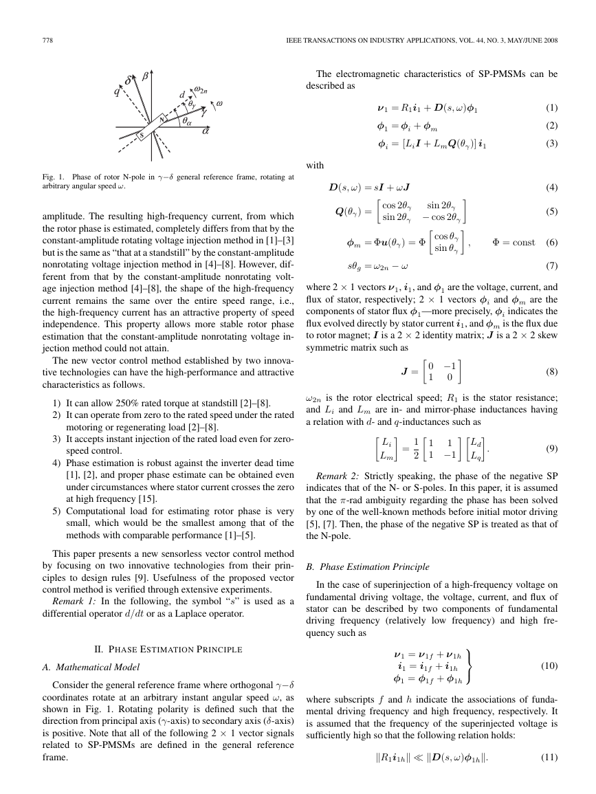
Fig. 1. Phase of rotor N-pole in γ−δ general reference frame, rotating at
arbitrary angular speed ω.
with
amplitude. The resulting high-frequency current, from which
the rotor phase is estimated, completely differs from that by the
constant-amplitude rotating voltage injection method in [1]–[3]
but is the same as “that at a standstill” by the constant-amplitude
nonrotating voltage injection method in [4]–[8]. However, dif-
ferent from that by the constant-amplitude nonrotating volt-
age injection method [4]–[8], the shape of the high-frequency
current remains the same over the entire speed range, i.e.,
the high-frequency current has an attractive property of speed
independence. This property allows more stable rotor phase
estimation that the constant-amplitude nonrotating voltage in-
jection method could not attain.
The new vector control method established by two innova-
tive technologies can have the high-performance and attractive
characteristics as follows.
1) It can allow 250% rated torque at standstill [2]–[8].
2) It can operate from zero to the rated speed under the rated
motoring or regenerating load [2]–[8].
3) It accepts instant injection of the rated load even for zero-
speed control.
4) Phase estimation is robust against the inverter dead time
[1], [2], and proper phase estimate can be obtained even
under circumstances where stator current crosses the zero
at high frequency [15].
5) Computational load for estimating rotor phase is very
small, which would be the smallest among that of the
methods with comparable performance [1]–[5].
This paper presents a new sensorless vector control method
by focusing on two innovative technologies from their prin-
ciples to design rules [9]. Usefulness of the proposed vector
control method is verified through extensive experiments.
Remark 1: In the following, the symbol “s” is used as a
differential operator d/dt or as a Laplace operator.
II. PHASE ESTIMATION PRINCIPLE
A. Mathematical Model
Consider the general reference frame where orthogonal γ−δ
coordinates rotate at an arbitrary instant angular speed ω, as
shown in Fig. 1. Rotating polarity is defined such that the
direction from principal axis (γ-axis) to secondary axis (δ-axis)
is positive. Note that all of the following 2 × 1 vector signals
related to SP-PMSMs are defined in the general reference
frame.
ν1 = R1i1 + D(s, ω)φ1
φ1 = φi + φm
φi = [LiI + LmQ(θγ)] i1
(1)
(2)
(3)
(4)
(5)
Φ = const
(6)
Q(θγ) =
D(s, ω) = sI + ωJ
cos 2θγ
sin 2θγ
sin 2θγ − cos 2θγ
cos θγ
sin θγ
φm = Φu(θγ) = Φ
sθg = ω2n − ω
,
(7)
where 2 × 1 vectors ν1, i1, and φ1 are the voltage, current, and
flux of stator, respectively; 2 × 1 vectors φi and φm are the
components of stator flux φ1—more precisely, φi indicates the
flux evolved directly by stator current i1, and φm is the flux due
to rotor magnet; I is a 2 × 2 identity matrix; J is a 2 × 2 skew
symmetric matrix such as
0 −1
0
1
J =
ω2n is the rotor electrical speed; R1 is the stator resistance;
and Li and Lm are in- and mirror-phase inductances having
a relation with d- and q-inductances such as
Li
Lm
=
1
2
1
1
1 −1
Ld
Lq
.
(9)
Remark 2: Strictly speaking, the phase of the negative SP
indicates that of the N- or S-poles. In this paper, it is assumed
that the π-rad ambiguity regarding the phase has been solved
by one of the well-known methods before initial motor driving
[5], [7]. Then, the phase of the negative SP is treated as that of
the N-pole.
B. Phase Estimation Principle
In the case of superinjection of a high-frequency voltage on
fundamental driving voltage, the voltage, current, and flux of
stator can be described by two components of fundamental
driving frequency (relatively low frequency) and high fre-
quency such as
ν1 = ν1f + ν1h
i1 = i1f + i1h
φ1 = φ1f + φ1h
(8)
(10)
where subscripts f and h indicate the associations of funda-
mental driving frequency and high frequency, respectively. It
is assumed that the frequency of the superinjected voltage is
sufficiently high so that the following relation holds:
R1i1h D(s, ω)φ1h
.
(11)
�
SHINNAKA: NEW SPEED-VARYING ELLIPSE VOLTAGE INJECTION METHOD FOR SENSORLESS DRIVE OF PMSMs
779
In the case where (10) holds, the following relation about the
high-frequency components of stator signals ν1h, i1h, and φ1h
can be obtained from (1)–(3) and (10):
2) The product of the first and second components of (15)
immediately yields the first relation in (16). Applying the
following relation
ν1h = D(s, ω)φ1h
φ1h = [LiI + LmQ(θγ)] i1h.
(12)
(13)
For high-frequency stator signals ν1h, i1h, and φ1h in (12)
and (13), the following useful theorem holds.
Theorem 1 (Speed-Varying Ellipse Voltage Theorem):
1) If high-frequency voltage ν1h is selected to be a speed-
varying signal such as
ν1h = Vh
cos ωht
sin ωht
ω
ωh
,
Vh = const
ωh = const
(14)
where Vh and ωh are constants and ω is the angular speed
of the γ−δ coordinates (refer to Fig. 1), then the high-
frequency current i1h as a response of the voltage turns
out to be
i1h = Vh
ωhLdLq
Li − Lm cos 2θγ
−Lm sin 2θγ
sin ωht.
(15)
2) Let iγh and iδh be the γ- and δ-axis components of the
high-frequency current i1h. The signal by multiplication
of two components of the high-frequency current
in
(15) is reconstructed as a linear combination of a zero-
frequency component ci1 having rotor phase information
and a 2ωh high-frequency component ci2, namely
iγhiδh = (2 sin2 ωht)ci1 = ci1 + ci2
(16)
with
Proof:
−V 2
h Lm
2ω2
hL2
dL2
q
ci1 =
ci2 = − ci1 cos 2ωht.
(Li − Lm cos 2θγ) sin 2θγ (17a)
(17b)
with
2 sin2 ωht = (1 − cos 2ωht)
(20)
to the first relation yields the second relation in (16).
Note that the high-frequency voltage in (14) tracks a tra-
jectory of an ellipse shape. Although the major axis com-
ponent of the ellipse is constant, the minor axis component
varies proportionally to the speed ω of the γ−δ coordinates,
which are expected to keep track of the d−q coordinates as
will be explained later. Amplitudes of the major and minor
axes are not the same in general; in addition, the minor axis
component varies with the rotor speed. These facts mean that
the high-frequency voltage in (14) has no longer constant
amplitude.
As a useful effect of the speed variance of the high-frequency
voltage, the associated high-frequency current can be inde-
pendent of the speed, i.e., the relation in (15) is valid for all
rotor speeds and is independent of the rotor speed. The rotor
phase is detected through processing the high-frequency cur-
rent. Because the characteristics of the high-frequency current
are speed independent, the rotor-phase overall speed range can
be detected just like at a standstill. In other words, the high-
frequency voltage injection method can be used stably in the
higher speed range. The speed-independence characteristics
of the high-frequency current play a key role in order that
phase estimation methods using the high-frequency current can
operate stably in wide speed range.
As (15) clearly shows, the high-frequency current has infor-
mation of the rotor phase θγ. The subsequent problem after the
speed-independent high-frequency current is obtained is how
to extract the phase information from the current. Consider
the case where the γ−δ coordinates keep track of the d−q
coordinates with a small rotor phase θγ. In that case, the zero-
frequency (in other words, dc) component ci1 in (17a) can be
approximated as
ci1 ≈ Kθθγ
Kθ =
−V 2
ω2
hL2
h Lm
dLq
> 0.
(21)
(22)
1) Equations (12) and (13) can be solved with respect to the
high-frequency current as
−1 D
[LiI−LmQ(θγ)]
i1h = [LiI +LmQ(θγ)]
=
1
LdLq
−1(s, ω)ν 1h
s2+ω2 D(s,−ω)ν1h.
1
Substituting (14) into (18) yields
i1h =
1
LdLq
[LiI − LmQ(θγ)]
Vh
ωh
sin ωht
0
which leads to (15).
(18)
(19)
The constant high-frequency ωh and amplitude Vh imply that
Kθ defined in (22) is a positive constant. Consequently, in the
case, a simple linear relation holds between the rotor phase θγ
evaluated in the γ−δ reference frame and the zero-frequency
component ci1 of the high-frequency current component multi-
plied signal (refer to the following Remark 3).
The principle of the proposed phase estimation method is to
estimate the rotor phase evaluated in the α−β (stator) reference
frame using the component multiplied signal in (16), which is
originally caused by injection of the high-frequency voltage in
shape of speed-varying ellipse in (14) in the γ−δ coordinates
�
780
IEEE TRANSACTIONS ON INDUSTRY APPLICATIONS, VOL. 44, NO. 3, MAY/JUNE 2008
keeping track of the d−q coordinates. In more detail, the
estimation principle is realized by the following three steps.
1) Inject the high-frequency voltage in shape of speed-
varying ellipse in (14) in the γ−δ reference frame.
2) Detect the high-frequency current associated with the
voltage and produce the signal through multiplication by
two components of the current as in (16).
3) Estimate directly the rotor phase evaluated in the α−β
(stator) reference frame using the component multiplied
signal by exploiting the characteristics in (21) and (22).
Remark 3: The rotor phase appears in the high-frequency
current in the form in (15) that is the same as the one at
“a standstill” in [4]–[8]. The form implies that, as long as one
of the γ- and δ-components of the current is directly used for
the phase estimation, at least a nonunity parameter originating
from the motor parameters appears inevitably between the rotor
phase and the directly used signal. This characteristic is com-
mon to the phase estimations in the nonrotating high-frequency
voltage injection method in [4]–[8] and is not unique to (21).
In the aforementioned phase estimations, in which the FFT
method in [4] and [5], the scalar heterodyne method in [6], the
sign method in [7], and the high-frequency rotation method in
[8] are included, the existence of the nonunity parameter should
be taken into account.
III. GENERALIZED INTEGRAL-TYPE PLL DRIVEN BY
HIGH-FREQUENCY CURRENT COMPONENT
MULTIPLIED SIGNAL
A. Generalized Integral-Type PLL Method
This section explains the aforementioned step 3) in detail.
For sensorless vector controls of SP-PMSMs, the rotor phase
θα evaluated in the α−β (stator) reference frame is necessary
(refer to Fig. 1). In the situation that the γ−δ coordinates are
in phase with the d−q coordinates, the phase ˆθα of γ-axis
evaluated in the α−β reference frame can be a proper estimate
of the rotor phase. Universal methods for such coordinate syn-
chronization will be PLL methods typified by the generalized
integral-type PLL method such as
(23)
ω = CPLL(s)uPLL
ˆθα = 1
s ω
with
CPLL(s) = Cn(s)
Cd(s)
= cnmsm + cnm−1sm−1 + ··· + cn0
sm + cdm−1sm−1 + ··· + cd0
(24)
where uPLL is an input signal to PLL, and cdi and cni are the
constant parameters of the “PLL controller” CPLL(s) [1].
The original generalized integral-type PLL method assumes
that the input signal uPLL is a proper estimate of the rotor
phase θγ evaluated in the γ−δ reference frame and guarantees
proper “phase-lock” ˆθα → θα under the assumption [1]. This
paper newly proposes the direct use of the high-frequency
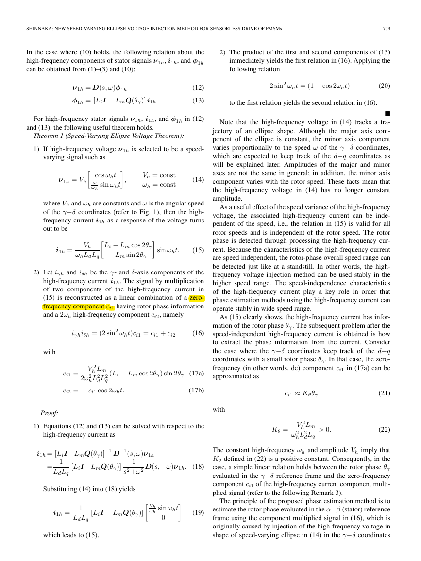
Fig. 2. Phase synchronizer as a realization of the generalized integral-type
PLL using input of the high-frequency current component multiplied signal.
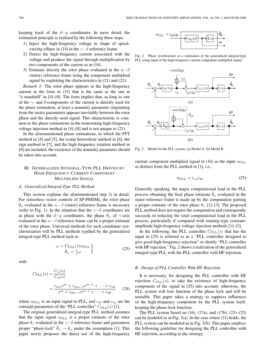
Fig. 3. Model for the PLL system. (a) Model A. (b) Model B.
current component multiplied signal in (16) as the input uPLL
as distinct from the PLL method in [1], i.e.,
uPLL = iγhiδh.
(25)
Generally speaking, the major computational load in the PLL
process obtaining the final phase estimate ˆθα evaluated in the
stator reference frame is made up by the computation gaining
a proper estimate of the rotor phase θγ [1]–[3]. The proposed
PLL method does not require the computation and consequently
succeeds in reducing the total computational load in the PLL
process, particularly if compared with rotating-type constant-
amplitude high-frequency voltage injection methods [1]–[3].
In the following, the PLL controller CPLL(s) that has the
input in (25) is referred to as a “PLL controller designed to
give good high-frequency rejection” or shortly “PLL controller
with HF rejection.” Fig. 2 shows a realization of the generalized
integral-type PLL with the PLL controller with HF rejection.
B. Design of PLL Controller With HF Rejection
It is necessary, for designing the PLL controller with HF
rejection CPLL(s), to take the existence of high-frequency
component of the signal in (25) into account; otherwise, the
PLL system will lose function of the phase lock and will be
unstable. This paper takes a strategy to suppress influences
of the high-frequency component by the PLL system itself,
keeping the phase-lock function.
The PLL system based on (16), (17a), and (17b), (23)–(25)
can be modeled as in Fig. 3(a). In the case where (21) holds, the
PLL system can be modeled as in Fig. 3(b). This paper employs
the following guideline for designing the PLL controller with
HF rejection, according to the strategy.
�
SHINNAKA: NEW SPEED-VARYING ELLIPSE VOLTAGE INJECTION METHOD FOR SENSORLESS DRIVE OF PMSMs
781
Design Guidelines of PLL Controller With HF Rejection:
1) The mth-order polynomial Cd(s) has a factor of “s” in an
2) The (m + 1)th-order polynomial H(s) in (26) is the
independent form.
Hurwitz for every 0 < Kω ≤ 2
H(s) = sCd(s) + KωKθCn(s),
0 < Kω ≤ 2.
(26)
The purpose of guideline 1) is to prevent the high-frequency
component contained in the input signal in (25) from appearing
in coordinate speed ω at a constant speed drive. The purposes
of guideline 2) are to treat the high-frequency component as an
equivalent varying coefficient 0 < Kω ≤ 2 of the PLL system
[refer to Fig. 3(b)] and to design the PLL system to be stable.
The following theorem gives concrete design rules for first-
and second-order PLL controller with HF rejections, based on
the aforementioned guidelines.
Theorem 2 (PLL Controller Theorem):
1) If Cd(s) is designed to be a first-order polynomial
such as
CPLL(s) = cn1s + cn0
s
,
cn0 > 0
cn1 > 0
(27a)
(27b)
then polynomial H(s) results in the Hurwitz for every
0 < Kω ≤ 2.
2) If Cd(s) is designed to be a second-order polynomial
such as
CPLL(s) = cn1s + cn0
s(s + cd1)
cn0 > 0, cn1 > 0, cd1 > 0
cd1 > cn0
cn1
(28a)
(28b)
then polynomial H(s) results in the Hurwitz for every
0 < Kω ≤ 2.
Proof:
1) Consider a second-order polynomial A(s) such that
A(s) = s2 + a1s + a0.
(29)
The polynomial A(s) is the Hurwitz if and only if all
parameters ai’s are positive.
From (27a), the condition cn0 = 0 is necessary for
polynomial Cd(s) to have a factor of “s” in an indepen-
dent form. In this case, H(s) defined in (26) becomes a
second-order polynomial such as
The polynomial A(s) is the Hurwitz if and only
if all parameters ai’s are positive and the following
relation holds:
a0 < a1a2.
(32)
From (28a), the condition cn0 = 0 is necessary for
polynomial Cd(s) to have a factor of “s” in an indepen-
dent form. In this case, H(s) defined in (26) becomes a
third-order polynomial such as
H(s) = s3 + cd1s2 + KωKθ(cn1s + cn0).
(33)
According to the aforementioned general property, the
condition that the third-order H(s) in (33) results in the
Hurwitz for every 0 < Kω ≤ 2 is given by (28b).
The high-frequency component ci2 defined in (17b) contains
the case of instant occurrence of equivalent coefficient Kω = 0.
As shown in Fig. 3(b), the instant occurrence of Kω = 0 means
that the input to the PLL controller with HF rejection is zero.
Because the PLL controller with HF rejection has the integral
function according to the design guideline 1), interior and
output signals of the PLL controller with HF rejection basically
keep the values of just-before zero input, at instant of the zero
input. This implies that the PLL controller with HF rejection
shows the most desired response to the zero input and can keep
stability.
The PLL controller with HF rejection in (27a) and (27b)
and (28a) and (28b) does not explicitly present conditions
about equivalent coefficient 0 < Kω ≤2 equivalently expressing
effects of the high-frequency component, and as a matter of
form, the PLL controllers in (27a) and (27b) and (28a) and
(28b) accidentally appear similarly with the conventional ones
using estimate of rotor phase θγ as input [1]. However, as shown
in the proof, the PLL controllers in (27a) and (27b) and (28a)
and (28b) take influences of the high-frequency component into
account and are designed based on the strategy to suppress
the influences of the high-frequency component by the PLL
system itself. It is noteworthy that every conventional PLL
controller cannot be necessarily used as a PLL controller with
HF rejection.
Remark 4: The PLL controller with HF rejection in (28a)
can be treated as an integral (I) controller with a phase com-
pensator or as a proportional and integral (PI) controller with a
low-pass filter, i.e.,
·
cn1
s
=
cn1
cd1
+ cn0
cd1
s + cn0/cn1
s + cd1
1
s
·
cd1
s + cd1
.
H(s) = s2 + KωKθ(cn1s + cn0).
(30)
CPLL(s) =
According to the aforementioned general property, the
condition that the second-order H(s) in (30) results in
the Hurwitz for every 0 < Kω ≤ 2 is given by (27b).
2) Consider a third-order polynomial A(s) such that
A(s) = s3 + a2s2 + a1s + a0.
Note that these parameters cannot be designed independently,
as shown in (28b) of Theorem 2.
(31)
�
782
IEEE TRANSACTIONS ON INDUSTRY APPLICATIONS, VOL. 44, NO. 3, MAY/JUNE 2008
CHARACTERISTICS OF TEST MOTOR (SST4-20P4AEA-L)
TABLE I
C. Example of Design and Response
This section shows a design example of the PLL controller
with HF rejection and response examples of the PLL system
installed with the controller.
Example 1: Let the parameters of a test motor be those in
Table I, and let the parameters of speed-varying high-frequency
voltage in (14) be
Vh = 23
ωh = 2π · 400
.
(34)
In this case, Kθ in (22) becomes
Kθ =
−V 2
ω2
hL2
h Lm
dLq
= 0.0352251 > 0.
(35)
Consider (27a) and (27b) as a PLL controller with HF rejection,
and design the associated H(s) in (30) to have two stable
zeros at s = −75 for the midvalue Kω = 1. In this case, two
coefficients of the PLL controller with HF rejection are deter-
mined to be
cn0 = 1.59687 · 105 > 0
cn1 = 4.25833 · 103 > 0
(36)
which satisfies the parameter condition in (27b).
Using the PLL controller with HF rejection CPLL(s) with
parameters in (36), models A and B of the PLL system in
Fig. 3 were constructed. Experiment conditions were set such
that the test SP-PMSM is rotating at a constant electrical speed
of ω2n = 30 rad/s and that the PLL system starts to operate
with initial value ˆθα = 0 rad at instant of the actual phase
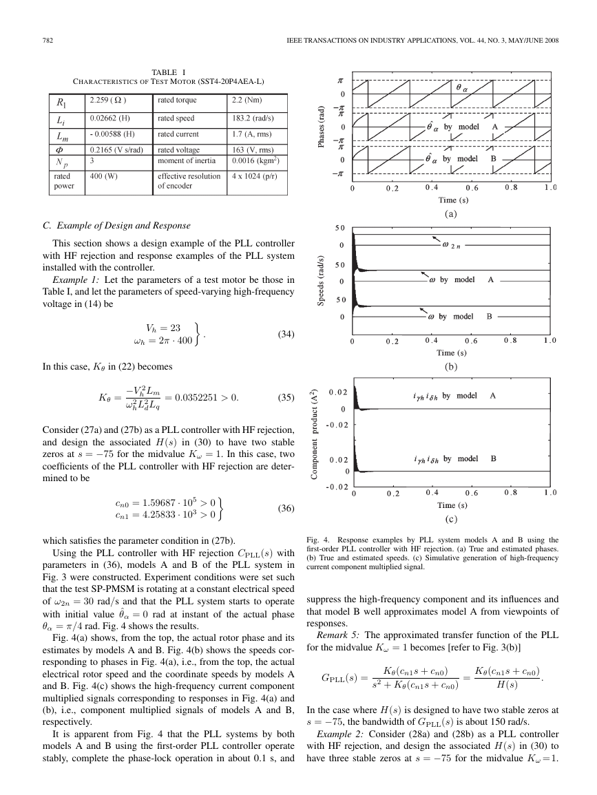
θα = π/4 rad. Fig. 4 shows the results.
Fig. 4(a) shows, from the top, the actual rotor phase and its
estimates by models A and B. Fig. 4(b) shows the speeds cor-
responding to phases in Fig. 4(a), i.e., from the top, the actual
electrical rotor speed and the coordinate speeds by models A
and B. Fig. 4(c) shows the high-frequency current component
multiplied signals corresponding to responses in Fig. 4(a) and
(b), i.e., component multiplied signals of models A and B,
respectively.
It is apparent from Fig. 4 that the PLL systems by both
models A and B using the first-order PLL controller operate
stably, complete the phase-lock operation in about 0.1 s, and
Fig. 4. Response examples by PLL system models A and B using the
first-order PLL controller with HF rejection. (a) True and estimated phases.
(b) True and estimated speeds. (c) Simulative generation of high-frequency
current component multiplied signal.
suppress the high-frequency component and its influences and
that model B well approximates model A from viewpoints of
responses.
Remark 5: The approximated transfer function of the PLL
for the midvalue Kω = 1 becomes [refer to Fig. 3(b)]
GPLL(s) = Kθ(cn1s + cn0)
s2 + Kθ(cn1s + cn0)
= Kθ(cn1s + cn0)
H(s)
.
In the case where H(s) is designed to have two stable zeros at
s = −75, the bandwidth of GPLL(s) is about 150 rad/s.
Example 2: Consider (28a) and (28b) as a PLL controller
with HF rejection, and design the associated H(s) in (30) to
have three stable zeros at s = −75 for the midvalue Kω =1.
�
SHINNAKA: NEW SPEED-VARYING ELLIPSE VOLTAGE INJECTION METHOD FOR SENSORLESS DRIVE OF PMSMs
783
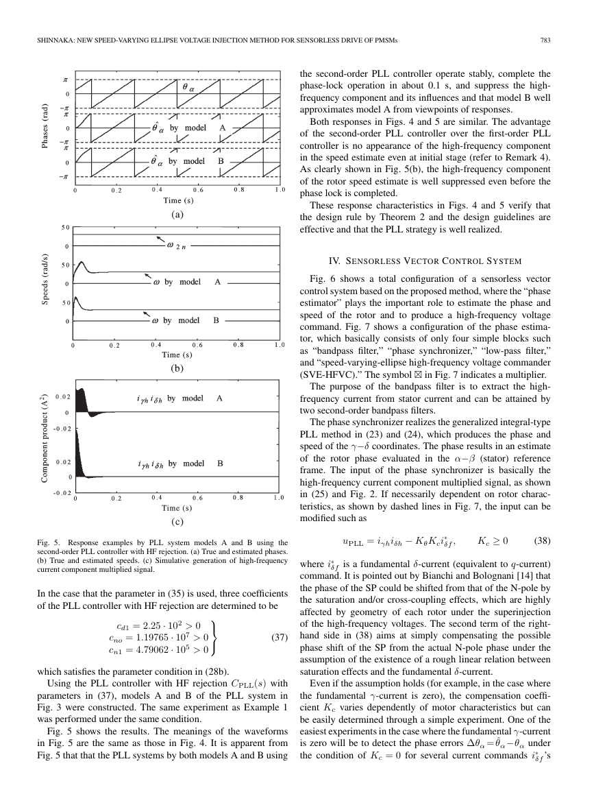
the second-order PLL controller operate stably, complete the
phase-lock operation in about 0.1 s, and suppress the high-
frequency component and its influences and that model B well
approximates model A from viewpoints of responses.
Both responses in Figs. 4 and 5 are similar. The advantage
of the second-order PLL controller over the first-order PLL
controller is no appearance of the high-frequency component
in the speed estimate even at initial stage (refer to Remark 4).
As clearly shown in Fig. 5(b), the high-frequency component
of the rotor speed estimate is well suppressed even before the
phase lock is completed.
These response characteristics in Figs. 4 and 5 verify that
the design rule by Theorem 2 and the design guidelines are
effective and that the PLL strategy is well realized.
IV. SENSORLESS VECTOR CONTROL SYSTEM
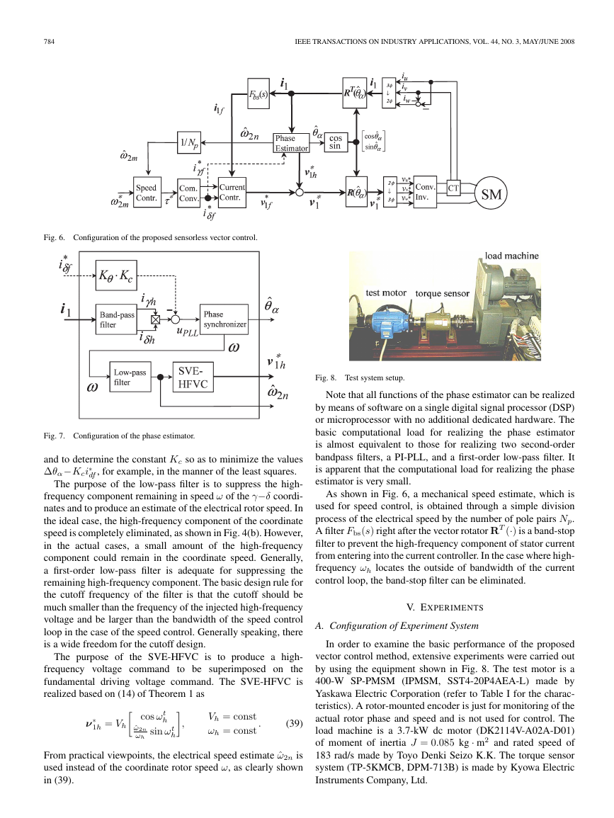
Fig. 6 shows a total configuration of a sensorless vector
control system based on the proposed method, where the “phase
estimator” plays the important role to estimate the phase and
speed of the rotor and to produce a high-frequency voltage
command. Fig. 7 shows a configuration of the phase estima-
tor, which basically consists of only four simple blocks such
as “bandpass filter,” “phase synchronizer,” “low-pass filter,”
and “speed-varying-ellipse high-frequency voltage commander
(SVE-HFVC).” The symbol in Fig. 7 indicates a multiplier.
The purpose of the bandpass filter is to extract the high-
frequency current from stator current and can be attained by
two second-order bandpass filters.
The phase synchronizer realizes the generalized integral-type
PLL method in (23) and (24), which produces the phase and
speed of the γ−δ coordinates. The phase results in an estimate
of the rotor phase evaluated in the α−β (stator) reference
frame. The input of the phase synchronizer is basically the
high-frequency current component multiplied signal, as shown
in (25) and Fig. 2. If necessarily dependent on rotor charac-
teristics, as shown by dashed lines in Fig. 7, the input can be
modified such as
uPLL = iγhiδh − KθKci
∗
δf ,
Kc ≥ 0
(38)
∗
δf is a fundamental δ-current (equivalent to q-current)
where i
command. It is pointed out by Bianchi and Bolognani [14] that
the phase of the SP could be shifted from that of the N-pole by
the saturation and/or cross-coupling effects, which are highly
affected by geometry of each rotor under the superinjection
of the high-frequency voltages. The second term of the right-
hand side in (38) aims at simply compensating the possible
phase shift of the SP from the actual N-pole phase under the
assumption of the existence of a rough linear relation between
saturation effects and the fundamental δ-current.
Even if the assumption holds (for example, in the case where
the fundamental γ-current is zero), the compensation coeffi-
cient Kc varies dependently of motor characteristics but can
be easily determined through a simple experiment. One of the
easiest experiments in the case where the fundamental γ-current
is zero will be to detect the phase errors ∆θα = ˆθα−θα under
∗
the condition of Kc = 0 for several current commands i
δf ’s
Fig. 5. Response examples by PLL system models A and B using the
second-order PLL controller with HF rejection. (a) True and estimated phases.
(b) True and estimated speeds. (c) Simulative generation of high-frequency
current component multiplied signal.
In the case that the parameter in (35) is used, three coefficients
of the PLL controller with HF rejection are determined to be
cd1 = 2.25 · 102 > 0
cno = 1.19765 · 107 > 0
cn1 = 4.79062 · 105 > 0
(37)
which satisfies the parameter condition in (28b).
Using the PLL controller with HF rejection CPLL(s) with
parameters in (37), models A and B of the PLL system in
Fig. 3 were constructed. The same experiment as Example 1
was performed under the same condition.
Fig. 5 shows the results. The meanings of the waveforms
in Fig. 5 are the same as those in Fig. 4. It is apparent from
Fig. 5 that that the PLL systems by both models A and B using
�
784
IEEE TRANSACTIONS ON INDUSTRY APPLICATIONS, VOL. 44, NO. 3, MAY/JUNE 2008
Fig. 6. Configuration of the proposed sensorless vector control.
Fig. 7. Configuration of the phase estimator.
and to determine the constant Kc so as to minimize the values
∆θα−Kci
∗
df , for example, in the manner of the least squares.
The purpose of the low-pass filter is to suppress the high-
frequency component remaining in speed ω of the γ−δ coordi-
nates and to produce an estimate of the electrical rotor speed. In
the ideal case, the high-frequency component of the coordinate
speed is completely eliminated, as shown in Fig. 4(b). However,
in the actual cases, a small amount of the high-frequency
component could remain in the coordinate speed. Generally,
a first-order low-pass filter is adequate for suppressing the
remaining high-frequency component. The basic design rule for
the cutoff frequency of the filter is that the cutoff should be
much smaller than the frequency of the injected high-frequency
voltage and be larger than the bandwidth of the speed control
loop in the case of the speed control. Generally speaking, there
is a wide freedom for the cutoff design.
The purpose of the SVE-HFVC is to produce a high-
frequency voltage command to be superimposed on the
fundamental driving voltage command. The SVE-HFVC is
realized based on (14) of Theorem 1 as
,
∗
1h = Vh
ν
cos ωt
h
ˆω2n
ωh
sin ωt
h
Vh = const
ωh = const .
(39)
From practical viewpoints, the electrical speed estimate ˆω2n is
used instead of the coordinate rotor speed ω, as clearly shown
in (39).
Fig. 8. Test system setup.
Note that all functions of the phase estimator can be realized
by means of software on a single digital signal processor (DSP)
or microprocessor with no additional dedicated hardware. The
basic computational load for realizing the phase estimator
is almost equivalent to those for realizing two second-order
bandpass filters, a PI-PLL, and a first-order low-pass filter. It
is apparent that the computational load for realizing the phase
estimator is very small.
As shown in Fig. 6, a mechanical speed estimate, which is
used for speed control, is obtained through a simple division
process of the electrical speed by the number of pole pairs Np.
A filter Fbs(s) right after the vector rotator RT (·) is a band-stop
filter to prevent the high-frequency component of stator current
from entering into the current controller. In the case where high-
frequency ωh locates the outside of bandwidth of the current
control loop, the band-stop filter can be eliminated.
V. EXPERIMENTS
A. Configuration of Experiment System
In order to examine the basic performance of the proposed
vector control method, extensive experiments were carried out
by using the equipment shown in Fig. 8. The test motor is a
400-W SP-PMSM (IPMSM, SST4-20P4AEA-L) made by
Yaskawa Electric Corporation (refer to Table I for the charac-
teristics). A rotor-mounted encoder is just for monitoring of the
actual rotor phase and speed and is not used for control. The
load machine is a 3.7-kW dc motor (DK2114V-A02A-D01)
of moment of inertia J = 0.085 kg · m2 and rated speed of
183 rad/s made by Toyo Denki Seizo K.K. The torque sensor
system (TP-5KMCB, DPM-713B) is made by Kyowa Electric
Instruments Company, Ltd.
�



 2023年江西萍乡中考道德与法治真题及答案.doc
 2012年重庆南川中考生物真题及答案.doc
 2013年江西师范大学地理学综合及文艺理论基础考研真题.doc
 2020年四川甘孜小升初语文真题及答案I卷.doc
 2020年注册岩土工程师专业基础考试真题及答案.doc
 2023-2024学年福建省厦门市九年级上学期数学月考试题及答案.doc
 2021-2022学年辽宁省沈阳市大东区九年级上学期语文期末试题及答案.doc
 2022-2023学年北京东城区初三第一学期物理期末试卷及答案.doc
 2018上半年江西教师资格初中地理学科知识与教学能力真题及答案.doc
 2012年河北国家公务员申论考试真题及答案-省级.doc
 2020-2021学年江苏省扬州市江都区邵樊片九年级上学期数学第一次质量检测试题及答案.doc
 2022下半年黑龙江教师资格证中学综合素质真题及答案.doc