一、实验目的:
1.熟悉 OPNET 软件的使用
2.建立更加高效的协议
3.设计简单的多路总线接口模型,包括 Aloha 模型和 CSMA 模型
4.执行参数的仿真
5.根据理论预测值进行仿真结果的分析,并对两种模型仿真结果进行比较
二、实验原理分析:
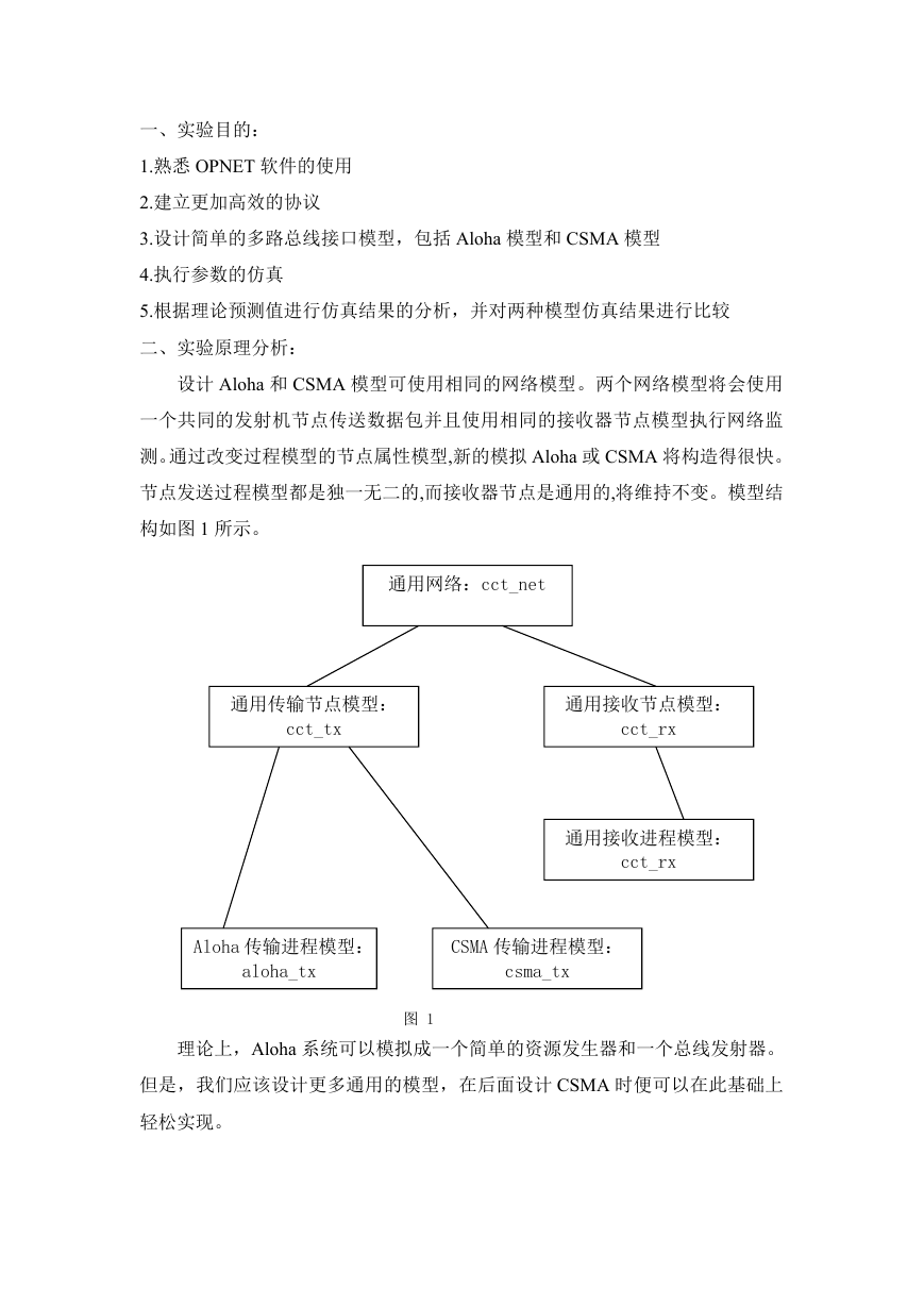
设计 Aloha 和 CSMA 模型可使用相同的网络模型。两个网络模型将会使用
一个共同的发射机节点传送数据包并且使用相同的接收器节点模型执行网络监
测。通过改变过程模型的节点属性模型,新的模拟 Aloha 或 CSMA 将构造得很快。
节点发送过程模型都是独一无二的,而接收器节点是通用的,将维持不变。模型结
构如图 1 所示。
通用网络:cct_net
通用传输节点模型:
cct_tx
通用接收节点模型:
cct_rx
通用接收进程模型:
cct_rx
Aloha 传输进程模型:
CSMA 传输进程模型:
aloha_tx
csma_tx
图 1
理论上,Aloha 系统可以模拟成一个简单的资源发生器和一个总线发射器。
但是,我们应该设计更多通用的模型,在后面设计 CSMA 时便可以在此基础上
轻松实现。
�
三、实验步骤:
1、创建 Aloha 发送进程模块
(1)启动 OPNET。
(2)选择 File>New…,选择 Process Model,点击 OK。
(3)利用 Create State 工具按钮,在工作空间中放置三个状态。
(4)对三个状态的属性进行设置,步骤如下:
a.将第一个状态的名字命名为 init,并将其状态改为强制类型。
b.将第二个状态的名字命名为 idle,并将其状态改为非强制类型。
c.将第三个状态的名字命名为 tx_pkt,并将其状态改为强制类型。
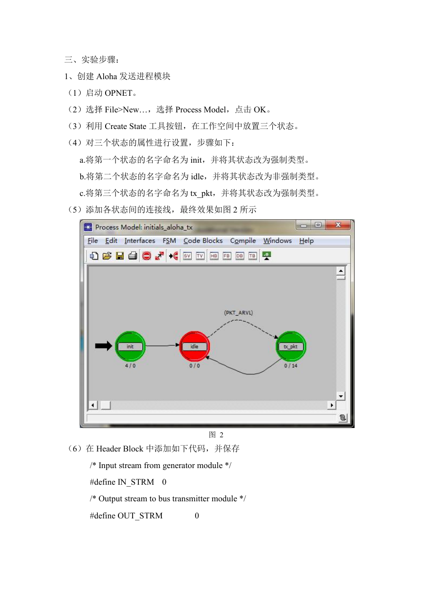
(5)添加各状态间的连接线,最终效果如图 2 所示
(6)在 Header Block 中添加如下代码,并保存
图 2
/* Input stream from generator module */
#define IN_STRM 0
/* Output stream to bus transmitter module */
#define OUT_STRM
0
�
/* Conditional macros */
#define PKT_ARVL (op_intrpt_type() == OPC_INTRPT_STRM)
/* Global Variable */
extern int subm_pkts;
(7)打开 State Variable Block 进行如图 3 所示设置
(8)定义 init 状态的动作,并添加如下执行代码
图 3
/* Get the maximum packet count, */
/* set at simulation run-time */
op_ima_sim_attr_get_int32 ("max packet count",
&max_packet_count);
(9)定义 tx_pkt 状态的动作,并添加如下执行代码
/* Outgoing packet */
Packet *out_pkt;
/* A packet has arrived for transmission. Acquire */
/* the packet from the input stream, send the packet */
/* and update the global submitted packet counter. */
out_pkt = op_pk_get (IN_STRM);
op_pk_send (out_pkt, OUT_STRM);
++subm_pkts;
�
/* Compare the total number of packets submitted with */
/* the maximum set for this simulation run.
If equal */
/* end the simulation run. */
if (subm_pkts == max_packet_count)
op_sim_end ("max packet count reached.", "", "", "");
(10) 定 义 一 个 全 局 属 性 , 它 将 被 设 定 在 仿 真 运 行 时 加 载 到 状 态 变 量
max_packet_count 中。
(11)编辑进程接口。
(12)编译进程模块,保存为 initial_aloha_tx。
2、创建通用发送节点模块
(1)选择 File>New…,选择 Node Model,点击 OK。
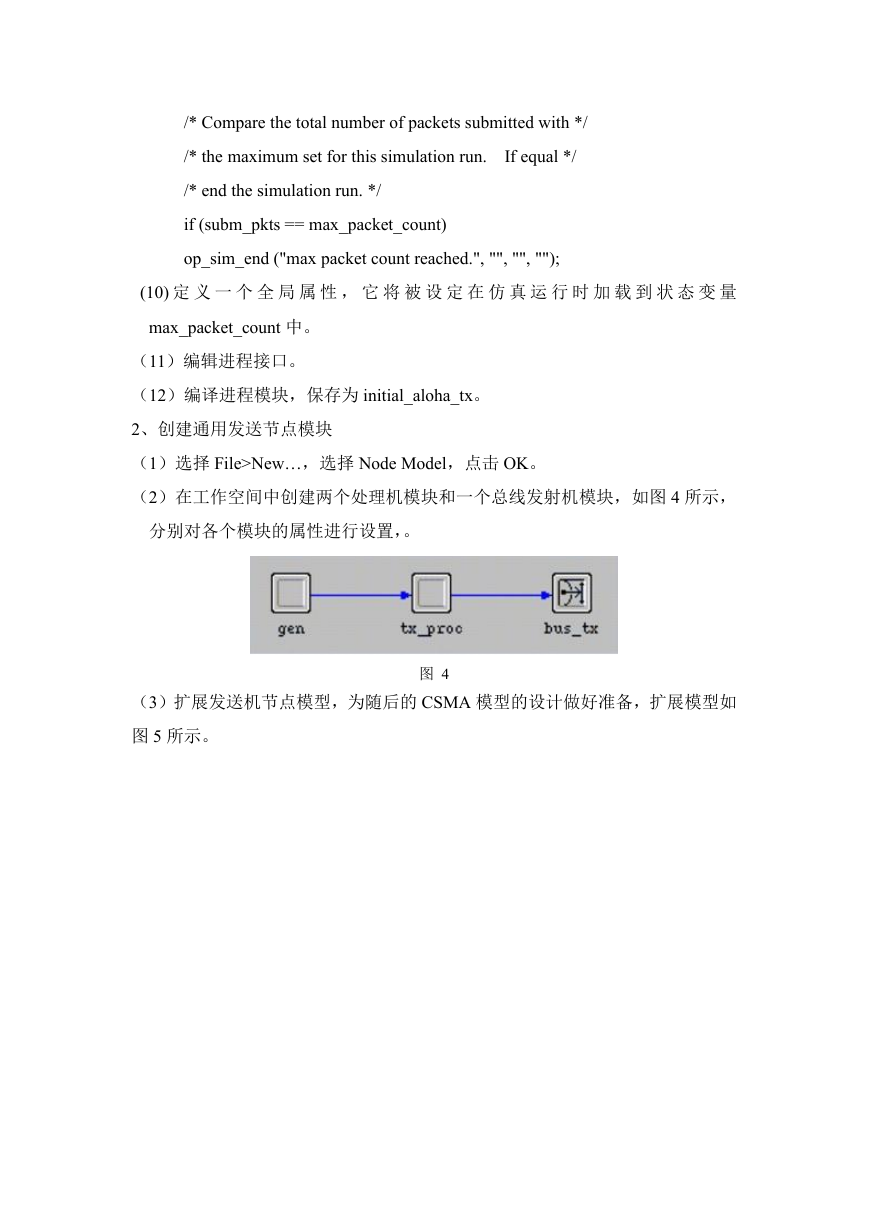
(2)在工作空间中创建两个处理机模块和一个总线发射机模块,如图 4 所示,
分别对各个模块的属性进行设置,。
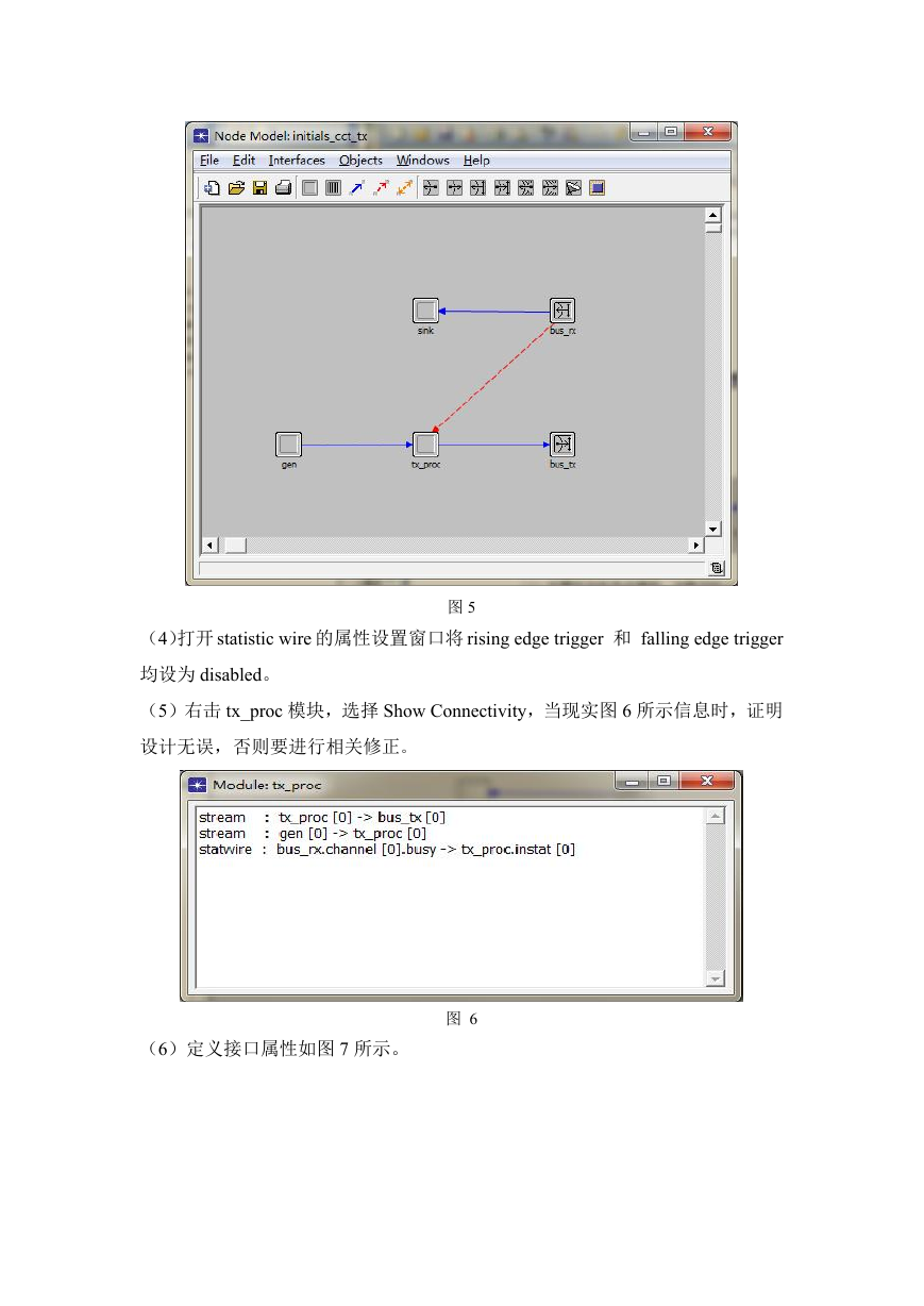
(3)扩展发送机节点模型,为随后的 CSMA 模型的设计做好准备,扩展模型如
图 5 所示。
图 4
�
图 5
(4)打开 statistic wire 的属性设置窗口将 rising edge trigger 和 falling edge trigger
均设为 disabled。
(5)右击 tx_proc 模块,选择 Show Connectivity,当现实图 6 所示信息时,证明
设计无误,否则要进行相关修正。
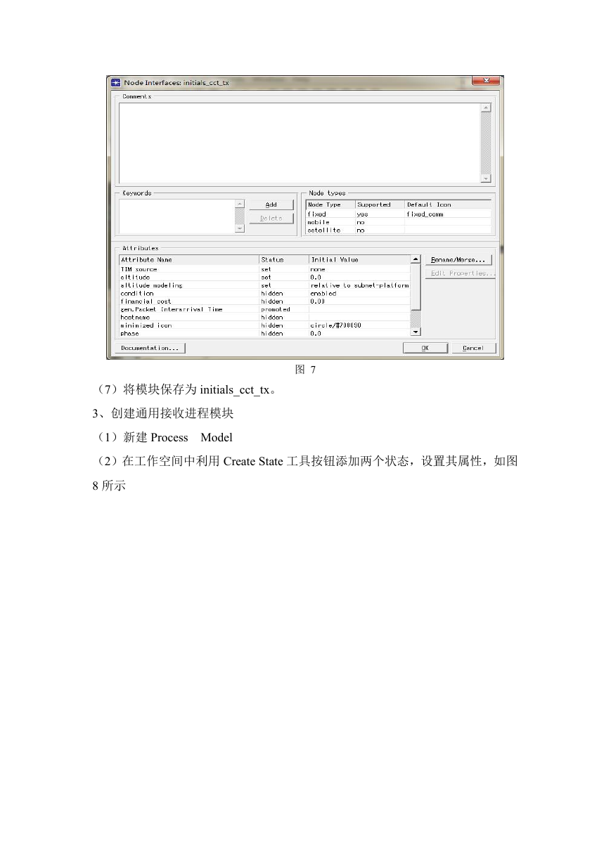
(6)定义接口属性如图 7 所示。
图 6
�
图 7
(7)将模块保存为 initials_cct_tx。
3、创建通用接收进程模块
(1)新建 Process Model
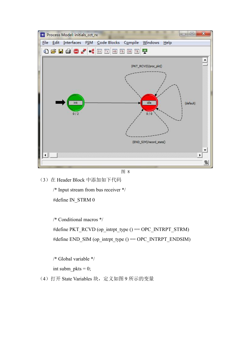
(2)在工作空间中利用 Create State 工具按钮添加两个状态,设置其属性,如图
8 所示
�
图 8
(3)在 Header Block 中添加如下代码
/* Input stream from bus receiver */
#define IN_STRM 0
/* Conditional macros */
#define PKT_RCVD (op_intrpt_type () == OPC_INTRPT_STRM)
#define END_SIM (op_intrpt_type () == OPC_INTRPT_ENDSIM)
/* Global variable */
int subm_pkts = 0;
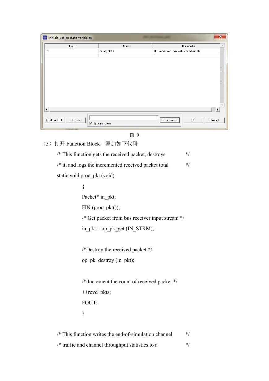
(4)打开 State Variables 块,定义如图 9 所示的变量
�
图 9
(5)打开 Function Block,添加如下代码
/* This function gets the received packet, destroys
/* it, and logs the incremented received packet total
static void proc_pkt (void)
*/
*/
{
Packet* in_pkt;
FIN (proc_pkt());
/* Get packet from bus receiver input stream */
in_pkt = op_pk_get (IN_STRM);
/*Destroy the received packet */
op_pk_destroy (in_pkt);
/* Increment the count of received packet */
++rcvd_pkts;
FOUT;
}
/* This function writes the end-of-simulation channel
/* traffic and channel throughput statistics to a
*/
*/
�



 2023年江西萍乡中考道德与法治真题及答案.doc
 2012年重庆南川中考生物真题及答案.doc
 2013年江西师范大学地理学综合及文艺理论基础考研真题.doc
 2020年四川甘孜小升初语文真题及答案I卷.doc
 2020年注册岩土工程师专业基础考试真题及答案.doc
 2023-2024学年福建省厦门市九年级上学期数学月考试题及答案.doc
 2021-2022学年辽宁省沈阳市大东区九年级上学期语文期末试题及答案.doc
 2022-2023学年北京东城区初三第一学期物理期末试卷及答案.doc
 2018上半年江西教师资格初中地理学科知识与教学能力真题及答案.doc
 2012年河北国家公务员申论考试真题及答案-省级.doc
 2020-2021学年江苏省扬州市江都区邵樊片九年级上学期数学第一次质量检测试题及答案.doc
 2022下半年黑龙江教师资格证中学综合素质真题及答案.doc