logo资料库

LLC杨波的论文.pdf

第1页 / 共332页
第2页 / 共332页
第3页 / 共332页
第4页 / 共332页
第5页 / 共332页
第6页 / 共332页
第7页 / 共332页
第8页 / 共332页
资料共332页,剩余部分请下载后查看
Front Page
Abstract
Table of Content
Ch1 Introduction
Ch2.pdf
State of the art topologies and improvements
Introduction
State of the art topologies and issues
Two-switch-forward converter
Phase Shift Full Bridge converter
Half bridge converter
Comparison of three topologies
Issue with hold up time requirement
Asymmetrical half bridge with hold up time design
Phase shift full bridge with hold up time design
Conclusion
Range winding for wide input range
Asymmetrical Winding Asymmetrical Half Bridge
QSW Synchronous Rectification
Synchronous Rectifier for front end DC/DC Converter
QSW Synchronous Rectifier
Summary and issues
Ch3.pdf
Integrated Power Electronics Module
Introduction
Integrated Power Electronics Module for Front end DC/DC
Active IPEM
Passive IPEM
Performance evaluation
Summary
Ch4.pdf
LLC Resonant Converter
Introduction
Three traditional resonant topologies
Series resonant converter
Parallel resonant converter
Series parallel resonant converter
LLC resonant converter
Operation of LLC resonant converter
Design of LLC resonant converter
Design of power stage parameters
Design trade offs:
Test results
Loss comparison
Extension of LLC resonant topology
High frequency operation
Summary
Ch5.pdf
Improvements of LLC Resonant Converter
Magnetic design for LLC Resonant Converter
Discrete design and issues
Integrated magnetic design
Real transformer with leakage and magnetizing inductance
Integrated magnetic design A
Extraction of Common Structure for Integrated Magnetic
Integrated magnetic design B for LLC resonant converter
Test Result
Summary
Over load protection for LLC resonant converter
Intrinsic response of LLC resonant converter to over load condition
Method 1: Increasing Switching Frequency
Method 2: Variable frequency control plus PWM Control
Method 3: LLC resonant converter with clamping diode
Integrated power electronics module for LLC
Summary
Ch6.pdf
Small signal analysis and control design of LLC converter
Introduction
Extended Describing Function analysis
Time domain simulation method
Small signal characteristic of LLC resonant converter
Impact of load variation on small signal characteristic
Impact of circuit parameters
Impact of output capacitance
Impact of magnetizing inductance
Impact of resonant tank impedance
Test verification
Compensator design for LLC resonant converter
Summary
Ch7.pdf
Summary and Future Work
Summary
Improvement of the state of the art topologies
LLC resonant converter
DC analysis of LLC resonant converter
Magnetic integration and over load protection
Small signal analysis of LLC resonant converter
Future work
Passive integration for LLC resonant converter
LLC resonant converter for other application
Small signal modeling of resonant converter
RefAppendixVita.pdf
Two and Three Components Resonant Tanks
Two resonant components resonant tank
Three resonant components resonant tank
Operation modes and DC analysis of LLC resonant converter
Operating modes of LLC resonant converter in Region 1
Operating modes of LLC resonant converter in Region 2
Operating modes of LLC resonant converter in Region 3
DC analysis of LLC resonant converter
Small signal characteristic of SRC converter
Small signal characteristic of SRC
LLC converter model for EDF analysis
Process of building LLC circuit model for EDF analysis
Model of LLC resonant converter in region 1
Model of LLC resonant converter in region 2
LLC resonant converter model
R
Reference
B. Resonant converter
C. Integrated Magnetic
D. Small Signal Modeling
E. General Textbooks
Vita
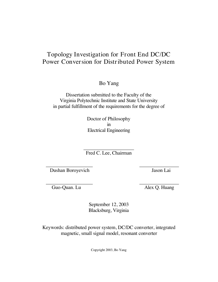
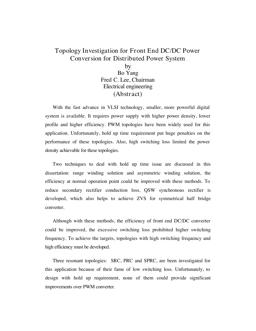
Topology Investigation for Front End DC/DC Power Conversion for Distributed Power System Bo Yang Dissertation submitted to the Faculty of the Virginia Polytechnic Institute and State University in partial fulfillment of the requirements for the degree of Dushan Boroyevich Jason Lai Guo-Quan. Lu Alex Q. Huang Keywords: distributed power system, DC/DC converter, integrated magnetic, small signal model, resonant converter Doctor of Philosophy in Electrical Engineering Fred C. Lee, Chairman September 12, 2003 Blacksburg, Virginia Copyright 2003, Bo Yang
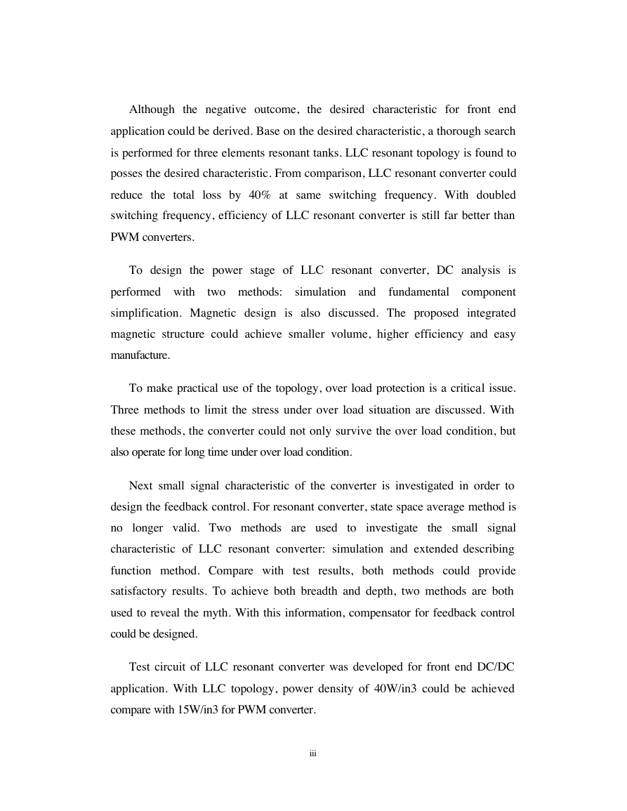
by Bo Yang Fred C. Lee, Chairman Electrical engineering (Abstract) Topology Investigation for Front End DC/DC Power Conversion for Distributed Power System With the fast advance in VLSI technology, smaller, more powerful digital system is available. It requires power supply with higher power density, lower profile and higher efficiency. PWM topologies have been widely used for this application. Unfortunately, hold up time requirement put huge penalties on the performance of these topologies. Also, high switching loss limited the power density achievable for these topologies. Two techniques to deal with hold up time issue are discussed in this dissertation: range winding solution and asymmetric winding solution, the efficiency at normal operation point could be improved with these methods. To reduce secondary rectifier conduction loss, QSW synchronous rectifier is developed, which also helps to achieve ZVS for symmetrical half bridge converter. Although with these methods, the efficiency of front end DC/DC converter could be improved, the excessive switching loss prohibited higher switching frequency. To achieve the targets, topologies with high switching frequency and high efficiency must be developed. Three resonant topologies: SRC, PRC and SPRC, are been investigated for this application because of their fame of low switching loss. Unfortunately, to design with hold up requirement, none of them could provide significant improvements over PWM converter.
Although the negative outcome, the desired characteristic for front end application could be derived. Base on the desired characteristic, a thorough search is performed for three elements resonant tanks. LLC resonant topology is found to posses the desired characteristic. From comparison, LLC resonant converter could reduce the total loss by 40% at same switching frequency. With doubled switching frequency, efficiency of LLC resonant converter is still far better than PWM converters. two methods: simulation and To design the power stage of LLC resonant converter, DC analysis is performed with fundamental component simplification. Magnetic design is also discussed. The proposed integrated magnetic structure could achieve smaller volume, higher efficiency and easy manufacture. To make practical use of the topology, over load protection is a critical issue. Three methods to limit the stress under over load situation are discussed. With these methods, the converter could not only survive the over load condition, but also operate for long time under over load condition. Next small signal characteristic of the converter is investigated in order to design the feedback control. For resonant converter, state space average method is no longer valid. Two methods are used to investigate the small signal characteristic of LLC resonant converter: simulation and extended describing function method. Compare with test results, both methods could provide satisfactory results. To achieve both breadth and depth, two methods are both used to reveal the myth. With this information, compensator for feedback control could be designed. Test circuit of LLC resonant converter was developed for front end DC/DC application. With LLC topology, power density of 40W/in3 could be achieved compare with 15W/in3 for PWM converter. iii
To My Wife Qiaoqiao iv
Bo Yang Acknowledgement ACKNOWLEDGMENT I would like to thank my advisor, Dr. Fred C. Lee. Till today, I am still amused by his great intuition, broad knowledge and accurate judgment. The most precious thing I learned from him is the attitude toward research, which can be applied to every aspects of life too. Without his guidance and challenging, I will never be able to achieve this. I am grateful to my committee: Dr. Dushan Boroyevich, Dr. Jason Lai, Dr. Alex Q. Huang and Dr. Guo Q. Lu, and Dr. Dan Y. Chen for their valuable suggestions and numerous help. It has been a great pleasure to work in the Center for Power Electronics Systems (CPES). I would like to acknowledge the CPES administrative and management staff, Ms. Teresa Shaw, Ms. Linda Gallagher, Ms. Trish Rose, Ms. Ann Craig, Ms. Marianne Hawthome, Ms. Elizabeth Tranter, Ms. Lesli Farmer, Mr. Robert Martin, Mr. Steve Z. Chen, Mr. Dan Huff, Mr. Gary Kerr, and Mr. Jamie Evans for their countless help. I would like to thank my colleagues, Dr. Qiong Li, Dr. Xunwei Zhou, Dr. Pitleong Wong, Dr. Richard Zhang, Dr. Kun Xing, Dr. Jindong Zhang, Dr.Fengfeng Tao, Dr. Weiyun Chen, Mr. David Wen, Mr. Deng-Ming Peng, Mr. Zhou Chen, Mr. Yuanxuan Hu, Dr. Yong Li, Mr. Wenkang Huang, Dr. Sihua Wen, Mr. Rengang Chen, Miss Jinghong Guo, Mr. Wei Xu, Mr. Zhenxue Xu, Dr. v
Bo Yang Acknowledgement Ming, Xu, Mr. Ho-Pu Wu, Mr. Xiaowu Sun, Mr. Kaiwei Yao, Mr. Yuhui Chen, Mr. Mao Ye, Mr. Yu Meng, Mr. Yuancheng Ren, Prof. Wei Chen and Prof. Xiaochuan Jia. Their friendships and help have made my stay at CPES pleasant and enjoyable. I am especially indebted to my teammates in the DPS group, Dr. Peter Barbosa, Dr. Qun Zhao, Dr. Francisco Canales, Dr. Wei Dong, Mr. Bing Lu, Mr. Yang Qiu, Mr. Liyu Yang, Miss Manjing Xie, Miss Juanjuan Sun, Miss Tina Sang, and Mr. Dianbo Fu. It was a pleasure to work with such a talented, hard- working and creative group. My heartfelt appreciation goes toward my father, Huairui Yang, who has always encouraged me to pursue higher education. I also want thank my sister, Jing, for her love and support to me. With deepest love, I would like to thank my wife, Qiaoqiao, who has always been there with her love, support, understanding and encouragement for all my endeavors. vi
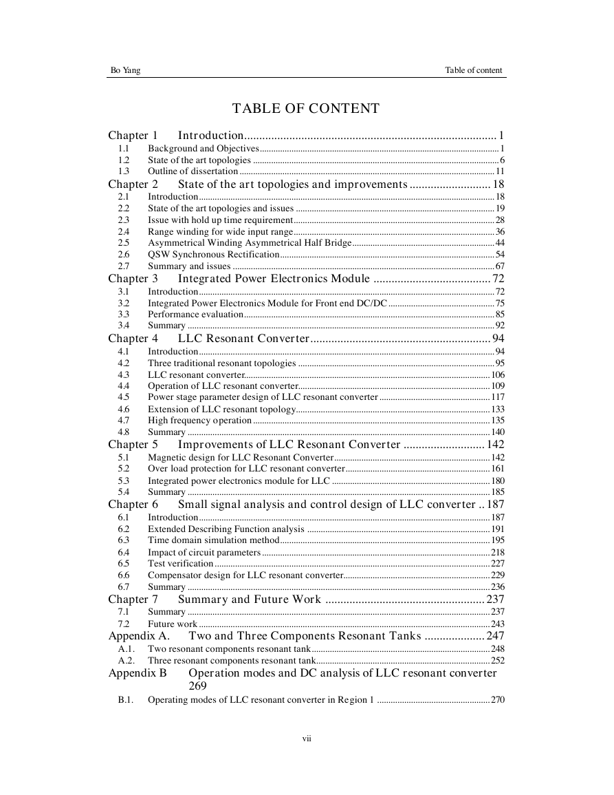
Chapter 3 3.1 3.2 3.3 3.4 Chapter 4 Chapter 1 1.1 1.2 1.3 Chapter 2 2.1 2.2 2.3 2.4 2.5 2.6 2.7 4.1 4.2 4.3 4.4 4.5 4.6 4.7 4.8 Introduction.................................................................................... 1 Background and Objectives.......................................................................................................... 1 State of the art topologies ............................................................................................................. 6 Outline of dissertation................................................................................................................. 11 State of the art topologies and improvements ........................... 18 Introduction................................................................................................................................... 18 State of the art topologies and issues ........................................................................................ 19 Issue with hold up time requirement......................................................................................... 28 Range winding for wide input range......................................................................................... 36 Asymmetrical Winding Asymmetrical Half Bridge............................................................... 44 QSW Synchronous Rectification............................................................................................... 54 Summary and issues .................................................................................................................... 67 Integrated Power Electronics Module ....................................... 72 Introduction................................................................................................................................... 72 Integrated Power Electronics Module for Front end DC/DC............................................... 75 Performance evaluation............................................................................................................... 85 Summary ........................................................................................................................................ 92 LLC Resonant Converter............................................................ 94 Introduction................................................................................................................................... 94 Three traditional resonant topologies ....................................................................................... 95 LLC resonant converter............................................................................................................. 106 Operation of LLC resonant converter..................................................................................... 109 Power stage parameter design of LLC resonant converter................................................. 117 Extension of LLC resonant topology...................................................................................... 133 High frequency operation......................................................................................................... 135 Summary ...................................................................................................................................... 140 Improvements of LLC Resonant Converter ........................... 142 5.1 Magnetic design for LLC Resonant Converter..................................................................... 142 Over load protection for LLC resonant converter................................................................ 161 5.2 5.3 Integrated power electronics module for LLC ...................................................................... 180 Summary ...................................................................................................................................... 185 5.4 Small signal analysis and control design of LLC converter .. 187 Introduction................................................................................................................................. 187 Extended Describing Function analysis ................................................................................. 191 Time domain simulation method............................................................................................. 195 Impact of circuit parameters..................................................................................................... 218 Test verification.......................................................................................................................... 227 Compensator design for LLC resonant converter................................................................. 229 Summary ...................................................................................................................................... 236 Summary and Future Work ..................................................... 237 Summary ...................................................................................................................................... 237 Future work................................................................................................................................. 243 Appendix A. Two and Three Components Resonant Tanks .................... 247 A.1. Two resonant components resonant tank............................................................................... 248 A.2. Three resonant components resonant tank............................................................................. 252 6.1 6.2 6.3 6.4 6.5 6.6 6.7 7.1 7.2 Chapter 7 Chapter 5 Chapter 6 Bo Yang Table of content TABLE OF CONTENT Appendix B Operation modes and DC analysis of LLC resonant converter 269 B.1. Operating modes of LLC resonant converter in Region 1 .................................................. 270 vii
Bo Yang Table of content B.2. Operating modes of LLC resonant converter in Region 2 .................................................. 276 B.3. Operating modes of LLC resonant converter in Region 3 .................................................. 282 B.4. DC analysis of LLC resonant converter................................................................................. 284 Appendix C. Small signal characteristic of SRC converter...................... 289 Appendix D. LLC converter model for EDF analysis ............................... 293 D.1. Process of building LLC circuit model for EDF analysis ................................................... 293 D.2. LLC resonant converter model ................................................................................................ 304 Reference...................................................................................................... 309 Vita ..................................................................................................................... 317 viii
分享到:
收藏