C:\Program Files\IAR FOR MSP430\iar\430\inc\msp430x14x.h
/********************************************************************
*
* Standard register and bit definitions for the Texas Instruments
* MSP430 microcontroller.
*
* This file supports assembler and C development for
* MSP430x14x devices.
*
* Texas Instruments, Version 2.4
*
* Rev. 1.2, Additional Timer B bit definitions.
* Renamed XTOFF to XT2OFF.
* Rev. 1.3, Removed leading 0 to aviod interpretation as octal
* values under C
* Included rather than "In430.h"
* Rev. 1.4, Corrected LPMx_EXIT to reference new intrinsic _BIC_SR_IRQ
* Changed TAIV and TBIV to be read-only
* Rev. 1.5, Enclose all #define statements with parentheses
* Rev. 1.6, Defined vectors for USART (in addition to UART)
* Rev. 1.7, Added USART special function labels (UxME, UxIE, UxIFG)
* Rev. 2.1, Alignment of defintions in Users Guide and of version numbers
* Rev. 2.2, Fixed type in ADC12 bit definitions (replaced ADC10 with ADC12)
* Rev. 2.3, Removed unused def of TASSEL2 / TBSSEL2
* Rev. 2.4, added definitions for Interrupt Vectors xxIV
*
********************************************************************/
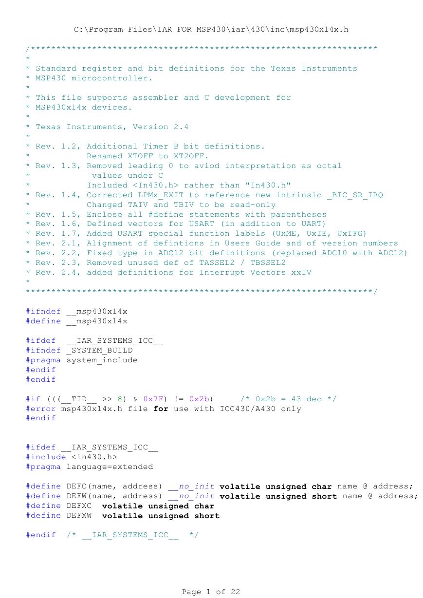
#ifndef __msp430x14x
#define __msp430x14x
#ifdef __IAR_SYSTEMS_ICC__
#ifndef _SYSTEM_BUILD
#pragma system_include
#endif
#endif
#if (((__TID__ >> 8) & 0x7F) != 0x2b) /* 0x2b = 43 dec */
#error msp430x14x.h file for use with ICC430/A430 only
#endif
#ifdef __IAR_SYSTEMS_ICC__
#include
#pragma language=extended
#define DEFC(name, address) __no_init volatile unsigned char name @ address;
#define DEFW(name, address) __no_init volatile unsigned short name @ address;
#define DEFXC volatile unsigned char
#define DEFXW volatile unsigned short
#endif /* __IAR_SYSTEMS_ICC__ */
Page 1 of 22
�
C:\Program Files\IAR FOR MSP430\iar\430\inc\msp430x14x.h
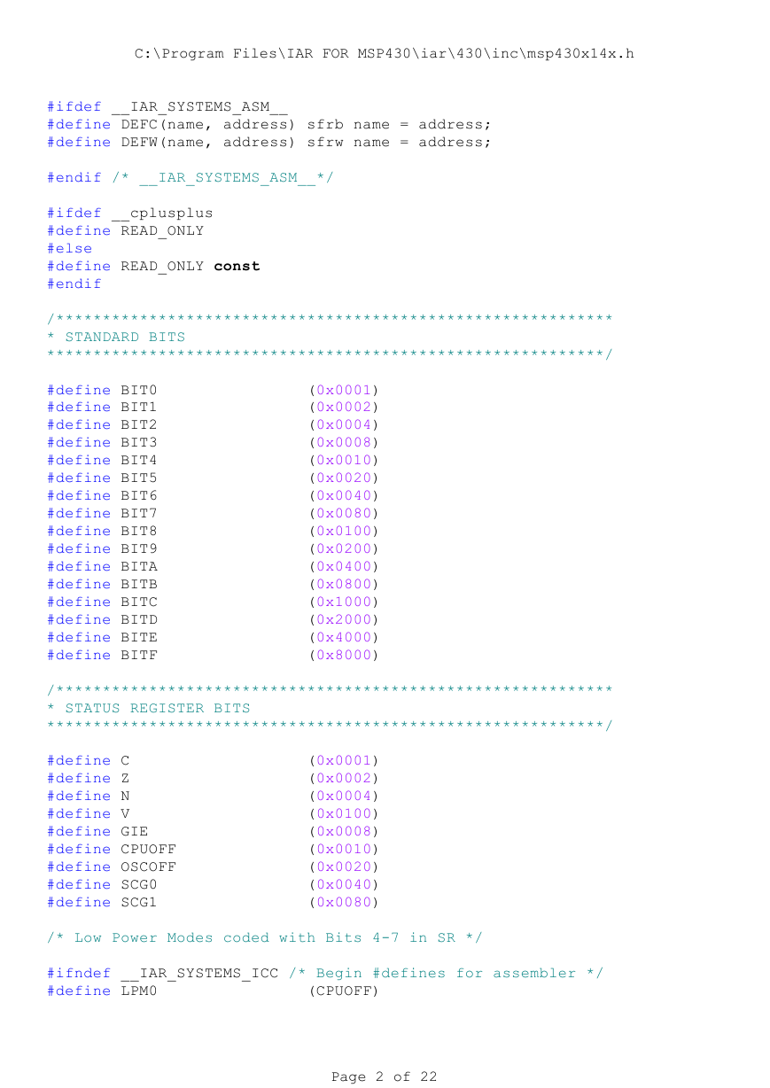
#ifdef __IAR_SYSTEMS_ASM__
#define DEFC(name, address) sfrb name = address;
#define DEFW(name, address) sfrw name = address;
#endif /* __IAR_SYSTEMS_ASM__*/
#ifdef __cplusplus
#define READ_ONLY
#else
#define READ_ONLY const
#endif
/************************************************************
* STANDARD BITS
************************************************************/
#define BIT0 (0x0001)
#define BIT1 (0x0002)
#define BIT2 (0x0004)
#define BIT3 (0x0008)
#define BIT4 (0x0010)
#define BIT5 (0x0020)
#define BIT6 (0x0040)
#define BIT7 (0x0080)
#define BIT8 (0x0100)
#define BIT9 (0x0200)
#define BITA (0x0400)
#define BITB (0x0800)
#define BITC (0x1000)
#define BITD (0x2000)
#define BITE (0x4000)
#define BITF (0x8000)
/************************************************************
* STATUS REGISTER BITS
************************************************************/
#define C (0x0001)
#define Z (0x0002)
#define N (0x0004)
#define V (0x0100)
#define GIE (0x0008)
#define CPUOFF (0x0010)
#define OSCOFF (0x0020)
#define SCG0 (0x0040)
#define SCG1 (0x0080)
/* Low Power Modes coded with Bits 4-7 in SR */
#ifndef __IAR_SYSTEMS_ICC /* Begin #defines for assembler */
#define LPM0 (CPUOFF)
Page 2 of 22
�
C:\Program Files\IAR FOR MSP430\iar\430\inc\msp430x14x.h
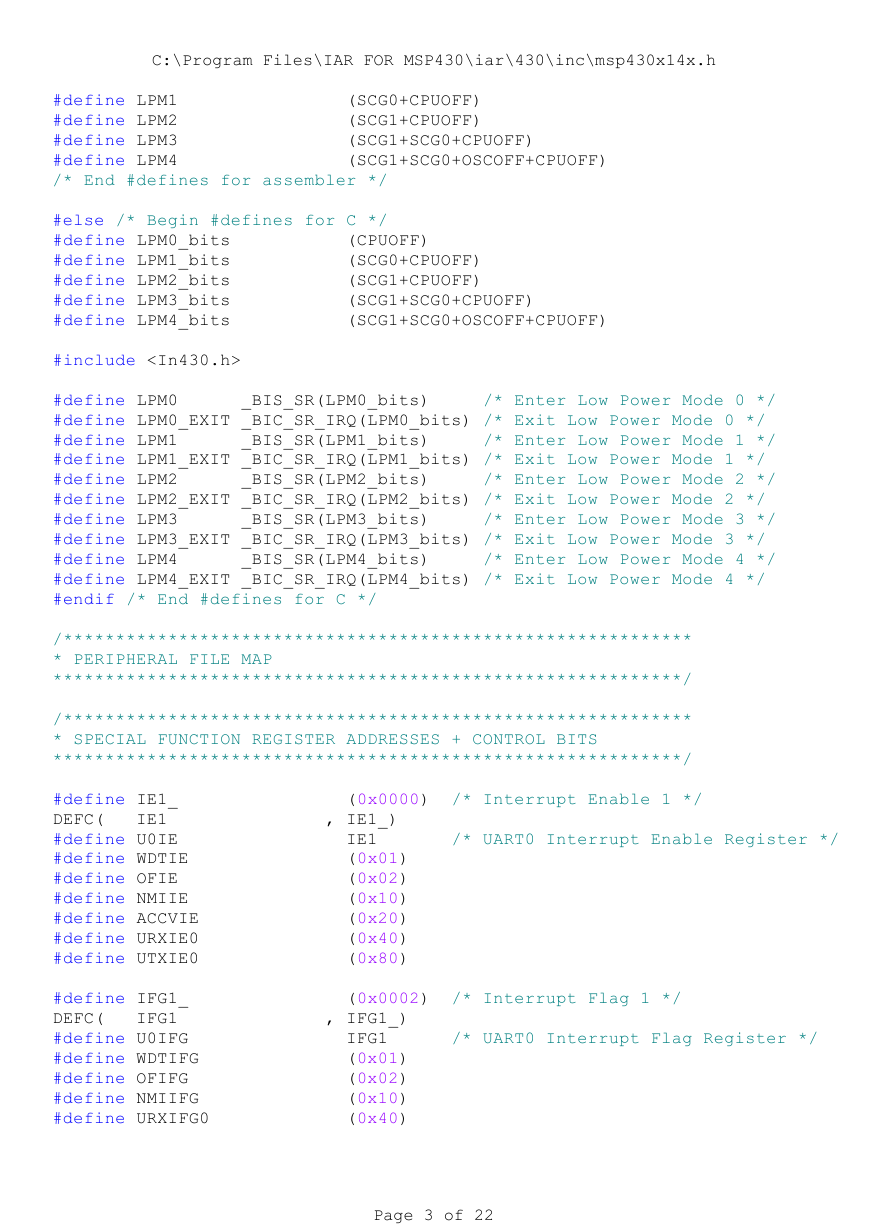
#define LPM1 (SCG0+CPUOFF)
#define LPM2 (SCG1+CPUOFF)
#define LPM3 (SCG1+SCG0+CPUOFF)
#define LPM4 (SCG1+SCG0+OSCOFF+CPUOFF)
/* End #defines for assembler */
#else /* Begin #defines for C */
#define LPM0_bits (CPUOFF)
#define LPM1_bits (SCG0+CPUOFF)
#define LPM2_bits (SCG1+CPUOFF)
#define LPM3_bits (SCG1+SCG0+CPUOFF)
#define LPM4_bits (SCG1+SCG0+OSCOFF+CPUOFF)
#include
#define LPM0 _BIS_SR(LPM0_bits) /* Enter Low Power Mode 0 */
#define LPM0_EXIT _BIC_SR_IRQ(LPM0_bits) /* Exit Low Power Mode 0 */
#define LPM1 _BIS_SR(LPM1_bits) /* Enter Low Power Mode 1 */
#define LPM1_EXIT _BIC_SR_IRQ(LPM1_bits) /* Exit Low Power Mode 1 */
#define LPM2 _BIS_SR(LPM2_bits) /* Enter Low Power Mode 2 */
#define LPM2_EXIT _BIC_SR_IRQ(LPM2_bits) /* Exit Low Power Mode 2 */
#define LPM3 _BIS_SR(LPM3_bits) /* Enter Low Power Mode 3 */
#define LPM3_EXIT _BIC_SR_IRQ(LPM3_bits) /* Exit Low Power Mode 3 */
#define LPM4 _BIS_SR(LPM4_bits) /* Enter Low Power Mode 4 */
#define LPM4_EXIT _BIC_SR_IRQ(LPM4_bits) /* Exit Low Power Mode 4 */
#endif /* End #defines for C */
/************************************************************
* PERIPHERAL FILE MAP
************************************************************/
/************************************************************
* SPECIAL FUNCTION REGISTER ADDRESSES + CONTROL BITS
************************************************************/
#define IE1_ (0x0000) /* Interrupt Enable 1 */
DEFC( IE1 , IE1_)
#define U0IE IE1 /* UART0 Interrupt Enable Register */
#define WDTIE (0x01)
#define OFIE (0x02)
#define NMIIE (0x10)
#define ACCVIE (0x20)
#define URXIE0 (0x40)
#define UTXIE0 (0x80)
#define IFG1_ (0x0002) /* Interrupt Flag 1 */
DEFC( IFG1 , IFG1_)
#define U0IFG IFG1 /* UART0 Interrupt Flag Register */
#define WDTIFG (0x01)
#define OFIFG (0x02)
#define NMIIFG (0x10)
#define URXIFG0 (0x40)
Page 3 of 22
�
C:\Program Files\IAR FOR MSP430\iar\430\inc\msp430x14x.h
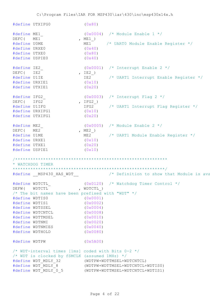
#define UTXIFG0 (0x80)
#define ME1_ (0x0004) /* Module Enable 1 */
DEFC( ME1 , ME1_)
#define U0ME ME1 /* UART0 Module Enable Register */
#define URXE0 (0x40)
#define UTXE0 (0x80)
#define USPIE0 (0x40)
#define IE2_ (0x0001) /* Interrupt Enable 2 */
DEFC( IE2 , IE2_)
#define U1IE IE2 /* UART1 Interrupt Enable Register */
#define URXIE1 (0x10)
#define UTXIE1 (0x20)
#define IFG2_ (0x0003) /* Interrupt Flag 2 */
DEFC( IFG2 , IFG2_)
#define U1IFG IFG2 /* UART1 Interrupt Flag Register */
#define URXIFG1 (0x10)
#define UTXIFG1 (0x20)
#define ME2_ (0x0005) /* Module Enable 2 */
DEFC( ME2 , ME2_)
#define U1ME ME2 /* UART1 Module Enable Register */
#define URXE1 (0x10)
#define UTXE1 (0x20)
#define USPIE1 (0x10)
/************************************************************
* WATCHDOG TIMER
************************************************************/
#define __MSP430_HAS_WDT__ /* Definition to show that Module is ava
#define WDTCTL_ (0x0120) /* Watchdog Timer Control */
DEFW( WDTCTL , WDTCTL_)
/* The bit names have been prefixed with "WDT" */
#define WDTIS0 (0x0001)
#define WDTIS1 (0x0002)
#define WDTSSEL (0x0004)
#define WDTCNTCL (0x0008)
#define WDTTMSEL (0x0010)
#define WDTNMI (0x0020)
#define WDTNMIES (0x0040)
#define WDTHOLD (0x0080)
#define WDTPW (0x5A00)
/* WDT-interval times [1ms] coded with Bits 0-2 */
/* WDT is clocked by fSMCLK (assumed 1MHz) */
#define WDT_MDLY_32 (WDTPW+WDTTMSEL+WDTCNTCL)
#define WDT_MDLY_8 (WDTPW+WDTTMSEL+WDTCNTCL+WDTIS0)
#define WDT_MDLY_0_5 (WDTPW+WDTTMSEL+WDTCNTCL+WDTIS1)
Page 4 of 22
�
C:\Program Files\IAR FOR MSP430\iar\430\inc\msp430x14x.h
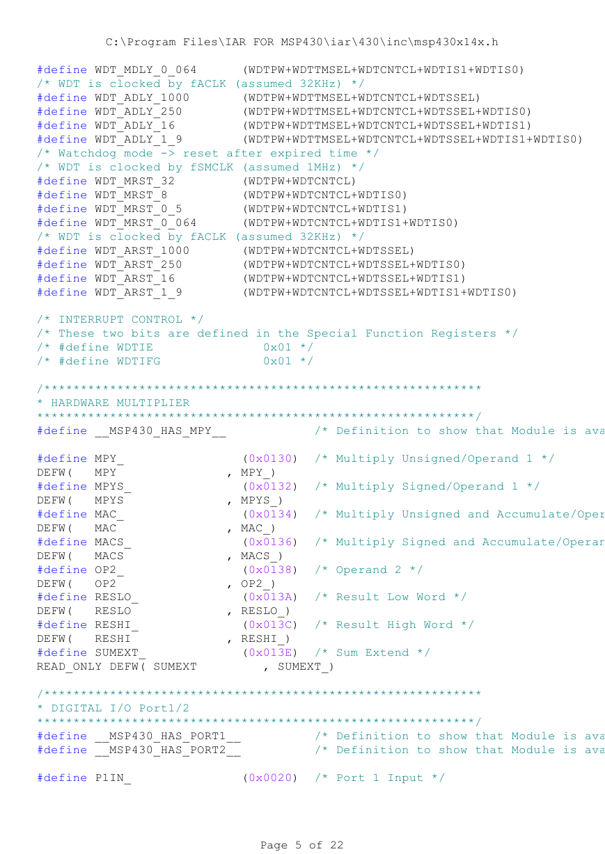
#define WDT_MDLY_0_064 (WDTPW+WDTTMSEL+WDTCNTCL+WDTIS1+WDTIS0)
/* WDT is clocked by fACLK (assumed 32KHz) */
#define WDT_ADLY_1000 (WDTPW+WDTTMSEL+WDTCNTCL+WDTSSEL)
#define WDT_ADLY_250 (WDTPW+WDTTMSEL+WDTCNTCL+WDTSSEL+WDTIS0)
#define WDT_ADLY_16 (WDTPW+WDTTMSEL+WDTCNTCL+WDTSSEL+WDTIS1)
#define WDT_ADLY_1_9 (WDTPW+WDTTMSEL+WDTCNTCL+WDTSSEL+WDTIS1+WDTIS0)
/* Watchdog mode -> reset after expired time */
/* WDT is clocked by fSMCLK (assumed 1MHz) */
#define WDT_MRST_32 (WDTPW+WDTCNTCL)
#define WDT_MRST_8 (WDTPW+WDTCNTCL+WDTIS0)
#define WDT_MRST_0_5 (WDTPW+WDTCNTCL+WDTIS1)
#define WDT_MRST_0_064 (WDTPW+WDTCNTCL+WDTIS1+WDTIS0)
/* WDT is clocked by fACLK (assumed 32KHz) */
#define WDT_ARST_1000 (WDTPW+WDTCNTCL+WDTSSEL)
#define WDT_ARST_250 (WDTPW+WDTCNTCL+WDTSSEL+WDTIS0)
#define WDT_ARST_16 (WDTPW+WDTCNTCL+WDTSSEL+WDTIS1)
#define WDT_ARST_1_9 (WDTPW+WDTCNTCL+WDTSSEL+WDTIS1+WDTIS0)
/* INTERRUPT CONTROL */
/* These two bits are defined in the Special Function Registers */
/* #define WDTIE 0x01 */
/* #define WDTIFG 0x01 */
/************************************************************
* HARDWARE MULTIPLIER
************************************************************/
#define __MSP430_HAS_MPY__ /* Definition to show that Module is ava
#define MPY_ (0x0130) /* Multiply Unsigned/Operand 1 */
DEFW( MPY , MPY_)
#define MPYS_ (0x0132) /* Multiply Signed/Operand 1 */
DEFW( MPYS , MPYS_)
#define MAC_ (0x0134) /* Multiply Unsigned and Accumulate/Oper
DEFW( MAC , MAC_)
#define MACS_ (0x0136) /* Multiply Signed and Accumulate/Operan
DEFW( MACS , MACS_)
#define OP2_ (0x0138) /* Operand 2 */
DEFW( OP2 , OP2_)
#define RESLO_ (0x013A) /* Result Low Word */
DEFW( RESLO , RESLO_)
#define RESHI_ (0x013C) /* Result High Word */
DEFW( RESHI , RESHI_)
#define SUMEXT_ (0x013E) /* Sum Extend */
READ_ONLY DEFW( SUMEXT , SUMEXT_)
/************************************************************
* DIGITAL I/O Port1/2
************************************************************/
#define __MSP430_HAS_PORT1__ /* Definition to show that Module is ava
#define __MSP430_HAS_PORT2__ /* Definition to show that Module is ava
#define P1IN_ (0x0020) /* Port 1 Input */
Page 5 of 22
�
C:\Program Files\IAR FOR MSP430\iar\430\inc\msp430x14x.h
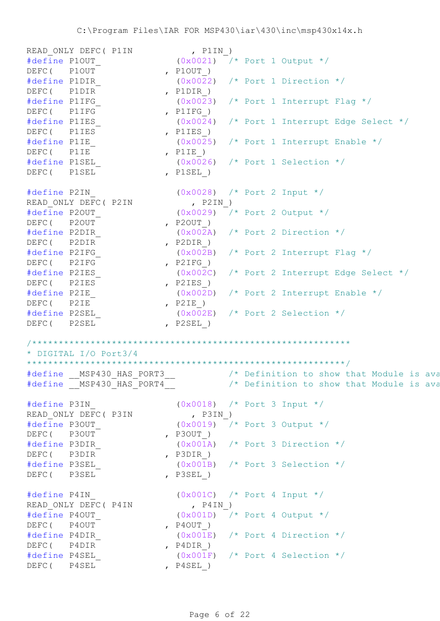
READ_ONLY DEFC( P1IN , P1IN_)
#define P1OUT_ (0x0021) /* Port 1 Output */
DEFC( P1OUT , P1OUT_)
#define P1DIR_ (0x0022) /* Port 1 Direction */
DEFC( P1DIR , P1DIR_)
#define P1IFG_ (0x0023) /* Port 1 Interrupt Flag */
DEFC( P1IFG , P1IFG_)
#define P1IES_ (0x0024) /* Port 1 Interrupt Edge Select */
DEFC( P1IES , P1IES_)
#define P1IE_ (0x0025) /* Port 1 Interrupt Enable */
DEFC( P1IE , P1IE_)
#define P1SEL_ (0x0026) /* Port 1 Selection */
DEFC( P1SEL , P1SEL_)
#define P2IN_ (0x0028) /* Port 2 Input */
READ_ONLY DEFC( P2IN , P2IN_)
#define P2OUT_ (0x0029) /* Port 2 Output */
DEFC( P2OUT , P2OUT_)
#define P2DIR_ (0x002A) /* Port 2 Direction */
DEFC( P2DIR , P2DIR_)
#define P2IFG_ (0x002B) /* Port 2 Interrupt Flag */
DEFC( P2IFG , P2IFG_)
#define P2IES_ (0x002C) /* Port 2 Interrupt Edge Select */
DEFC( P2IES , P2IES_)
#define P2IE_ (0x002D) /* Port 2 Interrupt Enable */
DEFC( P2IE , P2IE_)
#define P2SEL_ (0x002E) /* Port 2 Selection */
DEFC( P2SEL , P2SEL_)
/************************************************************
* DIGITAL I/O Port3/4
************************************************************/
#define __MSP430_HAS_PORT3__ /* Definition to show that Module is ava
#define __MSP430_HAS_PORT4__ /* Definition to show that Module is ava
#define P3IN_ (0x0018) /* Port 3 Input */
READ_ONLY DEFC( P3IN , P3IN_)
#define P3OUT_ (0x0019) /* Port 3 Output */
DEFC( P3OUT , P3OUT_)
#define P3DIR_ (0x001A) /* Port 3 Direction */
DEFC( P3DIR , P3DIR_)
#define P3SEL_ (0x001B) /* Port 3 Selection */
DEFC( P3SEL , P3SEL_)
#define P4IN_ (0x001C) /* Port 4 Input */
READ_ONLY DEFC( P4IN , P4IN_)
#define P4OUT_ (0x001D) /* Port 4 Output */
DEFC( P4OUT , P4OUT_)
#define P4DIR_ (0x001E) /* Port 4 Direction */
DEFC( P4DIR , P4DIR_)
#define P4SEL_ (0x001F) /* Port 4 Selection */
DEFC( P4SEL , P4SEL_)
Page 6 of 22
�
C:\Program Files\IAR FOR MSP430\iar\430\inc\msp430x14x.h
/************************************************************
* DIGITAL I/O Port5/6
************************************************************/
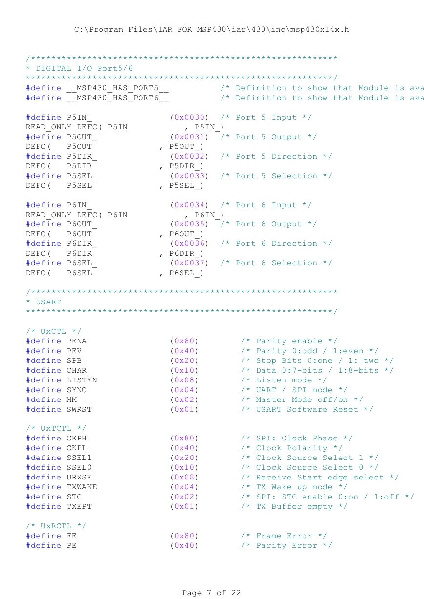
#define __MSP430_HAS_PORT5__ /* Definition to show that Module is ava
#define __MSP430_HAS_PORT6__ /* Definition to show that Module is ava
#define P5IN_ (0x0030) /* Port 5 Input */
READ_ONLY DEFC( P5IN , P5IN_)
#define P5OUT_ (0x0031) /* Port 5 Output */
DEFC( P5OUT , P5OUT_)
#define P5DIR_ (0x0032) /* Port 5 Direction */
DEFC( P5DIR , P5DIR_)
#define P5SEL_ (0x0033) /* Port 5 Selection */
DEFC( P5SEL , P5SEL_)
#define P6IN_ (0x0034) /* Port 6 Input */
READ_ONLY DEFC( P6IN , P6IN_)
#define P6OUT_ (0x0035) /* Port 6 Output */
DEFC( P6OUT , P6OUT_)
#define P6DIR_ (0x0036) /* Port 6 Direction */
DEFC( P6DIR , P6DIR_)
#define P6SEL_ (0x0037) /* Port 6 Selection */
DEFC( P6SEL , P6SEL_)
/************************************************************
* USART
************************************************************/
/* UxCTL */
#define PENA (0x80) /* Parity enable */
#define PEV (0x40) /* Parity 0:odd / 1:even */
#define SPB (0x20) /* Stop Bits 0:one / 1: two */
#define CHAR (0x10) /* Data 0:7-bits / 1:8-bits */
#define LISTEN (0x08) /* Listen mode */
#define SYNC (0x04) /* UART / SPI mode */
#define MM (0x02) /* Master Mode off/on */
#define SWRST (0x01) /* USART Software Reset */
/* UxTCTL */
#define CKPH (0x80) /* SPI: Clock Phase */
#define CKPL (0x40) /* Clock Polarity */
#define SSEL1 (0x20) /* Clock Source Select 1 */
#define SSEL0 (0x10) /* Clock Source Select 0 */
#define URXSE (0x08) /* Receive Start edge select */
#define TXWAKE (0x04) /* TX Wake up mode */
#define STC (0x02) /* SPI: STC enable 0:on / 1:off */
#define TXEPT (0x01) /* TX Buffer empty */
/* UxRCTL */
#define FE (0x80) /* Frame Error */
#define PE (0x40) /* Parity Error */
Page 7 of 22
�
C:\Program Files\IAR FOR MSP430\iar\430\inc\msp430x14x.h
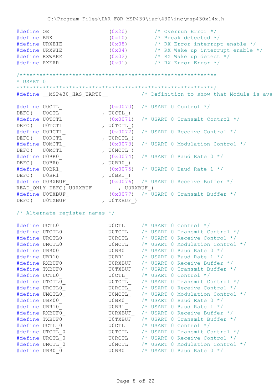
#define OE (0x20) /* Overrun Error */
#define BRK (0x10) /* Break detected */
#define URXEIE (0x08) /* RX Error interrupt enable */
#define URXWIE (0x04) /* RX Wake up interrupt enable */
#define RXWAKE (0x02) /* RX Wake up detect */
#define RXERR (0x01) /* RX Error Error */
/************************************************************
* USART 0
************************************************************/
#define __MSP430_HAS_UART0__ /* Definition to show that Module is ava
#define U0CTL_ (0x0070) /* USART 0 Control */
DEFC( U0CTL , U0CTL_)
#define U0TCTL_ (0x0071) /* USART 0 Transmit Control */
DEFC( U0TCTL , U0TCTL_)
#define U0RCTL_ (0x0072) /* USART 0 Receive Control */
DEFC( U0RCTL , U0RCTL_)
#define U0MCTL_ (0x0073) /* USART 0 Modulation Control */
DEFC( U0MCTL , U0MCTL_)
#define U0BR0_ (0x0074) /* USART 0 Baud Rate 0 */
DEFC( U0BR0 , U0BR0_)
#define U0BR1_ (0x0075) /* USART 0 Baud Rate 1 */
DEFC( U0BR1 , U0BR1_)
#define U0RXBUF_ (0x0076) /* USART 0 Receive Buffer */
READ_ONLY DEFC( U0RXBUF , U0RXBUF_)
#define U0TXBUF_ (0x0077) /* USART 0 Transmit Buffer */
DEFC( U0TXBUF , U0TXBUF_)
/* Alternate register names */
#define UCTL0 U0CTL /* USART 0 Control */
#define UTCTL0 U0TCTL /* USART 0 Transmit Control */
#define URCTL0 U0RCTL /* USART 0 Receive Control */
#define UMCTL0 U0MCTL /* USART 0 Modulation Control */
#define UBR00 U0BR0 /* USART 0 Baud Rate 0 */
#define UBR10 U0BR1 /* USART 0 Baud Rate 1 */
#define RXBUF0 U0RXBUF /* USART 0 Receive Buffer */
#define TXBUF0 U0TXBUF /* USART 0 Transmit Buffer */
#define UCTL0_ U0CTL_ /* USART 0 Control */
#define UTCTL0_ U0TCTL_ /* USART 0 Transmit Control */
#define URCTL0_ U0RCTL_ /* USART 0 Receive Control */
#define UMCTL0_ U0MCTL_ /* USART 0 Modulation Control */
#define UBR00_ U0BR0_ /* USART 0 Baud Rate 0 */
#define UBR10_ U0BR1_ /* USART 0 Baud Rate 1 */
#define RXBUF0_ U0RXBUF_ /* USART 0 Receive Buffer */
#define TXBUF0_ U0TXBUF_ /* USART 0 Transmit Buffer */
#define UCTL_0 U0CTL /* USART 0 Control */
#define UTCTL_0 U0TCTL /* USART 0 Transmit Control */
#define URCTL_0 U0RCTL /* USART 0 Receive Control */
#define UMCTL_0 U0MCTL /* USART 0 Modulation Control */
#define UBR0_0 U0BR0 /* USART 0 Baud Rate 0 */
Page 8 of 22
�


 2023年江西萍乡中考道德与法治真题及答案.doc
 2012年重庆南川中考生物真题及答案.doc
 2013年江西师范大学地理学综合及文艺理论基础考研真题.doc
 2020年四川甘孜小升初语文真题及答案I卷.doc
 2020年注册岩土工程师专业基础考试真题及答案.doc
 2023-2024学年福建省厦门市九年级上学期数学月考试题及答案.doc
 2021-2022学年辽宁省沈阳市大东区九年级上学期语文期末试题及答案.doc
 2022-2023学年北京东城区初三第一学期物理期末试卷及答案.doc
 2018上半年江西教师资格初中地理学科知识与教学能力真题及答案.doc
 2012年河北国家公务员申论考试真题及答案-省级.doc
 2020-2021学年江苏省扬州市江都区邵樊片九年级上学期数学第一次质量检测试题及答案.doc
 2022下半年黑龙江教师资格证中学综合素质真题及答案.doc