Simplorer
E.01
M01
Co-simulation with Maxwell
Example of co-simulation of Simplorer and Maxwell:
Motor-Drive simulation
i
l
i
i
i
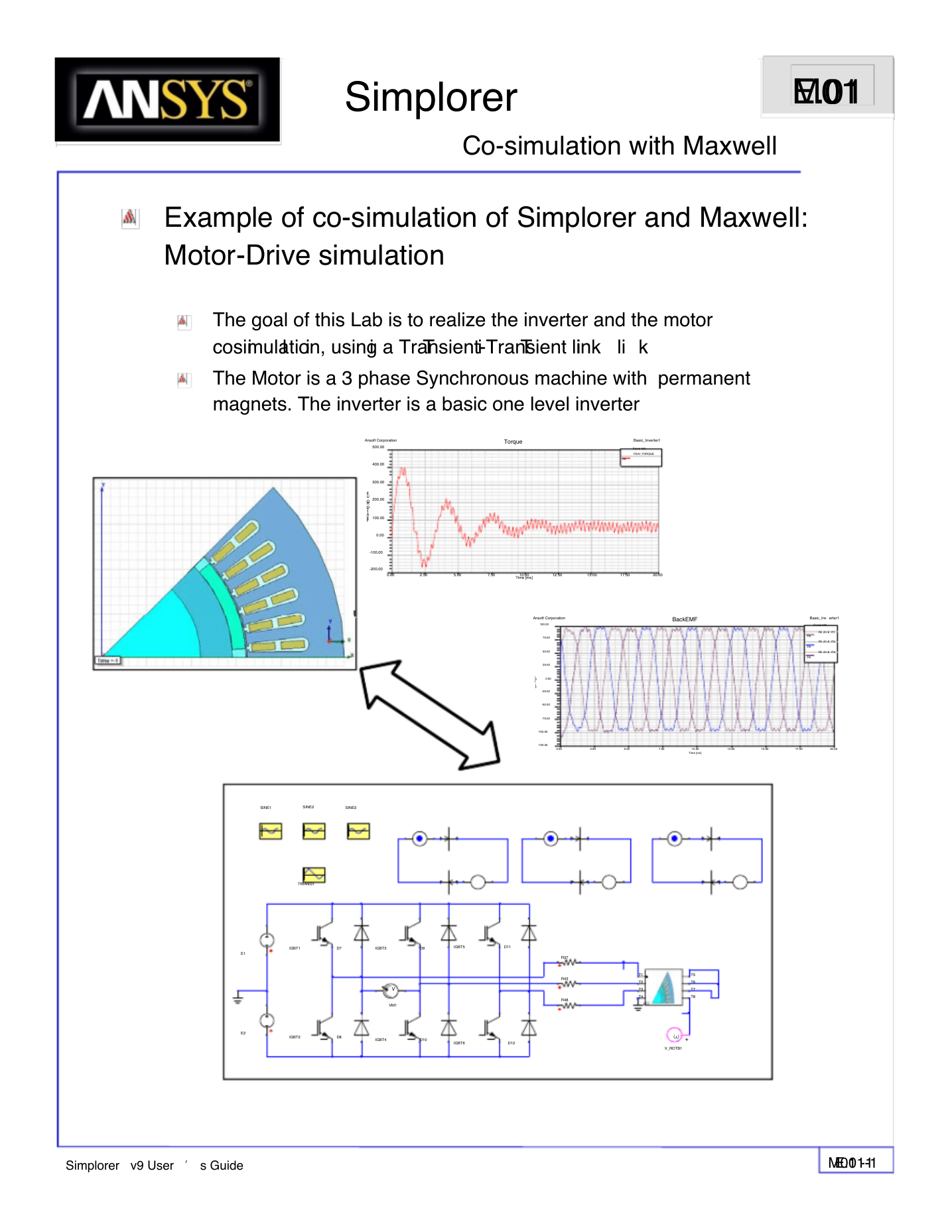
The goal of this Lab is to realize the inverter and the motor
cosimulation, using a Transient-Transient link
The Motor is a 3 phase Synchronous machine with permanent
magnets. The inverter is a basic one level inverter
li k
T
T
i
Torque
Basic_Inverter1
Curve Info
FEA1.TORQUE
TR
Ansoft Corporation
500.00
400.00
300.00
200.00
100.00
0.00
E
U
RQ
1.TO
A
E
F
-100.00
-200.00
0.00
2.50
5.00
7.50
10.00
Time [ms]
12.50
15.00
17.50
20.00
Ansoft Corporation
100.00
BackEMF
]
V
[
1
Y
75.00
50.00
25.00
0.00
-25.00
-50.00
-75.00
-100.00
-125.00
Basic_Inv erter1
Curve Info
FE A1.E IT1
FE A1.E IT2
FE A1.E IT3
TR
TR
TR
0.00
2.50
5.00
7.50
10.00
Time [ms]
12.50
15.00
17.50
20.00
SINE1
SINE2
SINE3
TRIANG1
E1
E2
IGBT1
D7
IGBT3
D9
IGBT5
D11
+
V
VM1
IGBT2
D8
IGBT4
D10
IGBT6
D12
R37
R43
R48
T1
T2
T3
T4
0
T5
T6
T7
T8
ω +
V_ROTB1
Simplorer v9 User ’ s Guide
E.01-1
M01 -1
�
Simplorer
E.01
M01
Co-simulation with Maxwell
Technical Background
The co-simulation is the most accurate way of coupling the drive and the motor
model. The advantage of this method is the high accuraty, having the real
inverter currents as source in Maxwell and the back emf of the motor on the
inverter currents as source in Maxwell, and the back-emf of the motor on the
inverter side.
The transient-transient link enables the use to pass data between Simplorer and
Maxwell during the simulation:
Maxwell2D and Maxwell3D can be used
Simplorer and Maxwell will run altogether
Simplorer is the Master, Maxwell is the slave
At a given time step, the Winding currents and the Rotor angle are passed
from Simplorer to Maxwell, the Back EMF and the Torque are passed from
Maxwell to Simplorer
The complexity of the drive system and of the mechanical system is not
The complexity of the drive system and of the mechanical system is not
limited
Insights on the coupling Method
0
The Simplorer time steps and the Maxwell time steps don
same. Usually, Simplorer requires much more time steps than Maxwell.
Assume the current simulation time is t
Simplorer, based on the previous time steps, gives a forward meeting time
t1 to Maxwell where both simulators will exchange data. Between t
both code run by themselves.
At t 1, both codes exchange data. If during the t
appears on Simplorer side (state graph transition, large change of the
dynamic of the circuit), Simplorer will roll back to t
meeting time t 1’, t1’< t1.
0-t1 period, some event
g p
pp
,
g
g
p
(
0 and set a new forward
’ t have to be the
0 and t 1,
Simplorer v9 User ’ s Guide
E.01-2
M01 -2
�
Simplorer
E.01
M01
Co-simulation with Maxwell
Simplorer Schematic
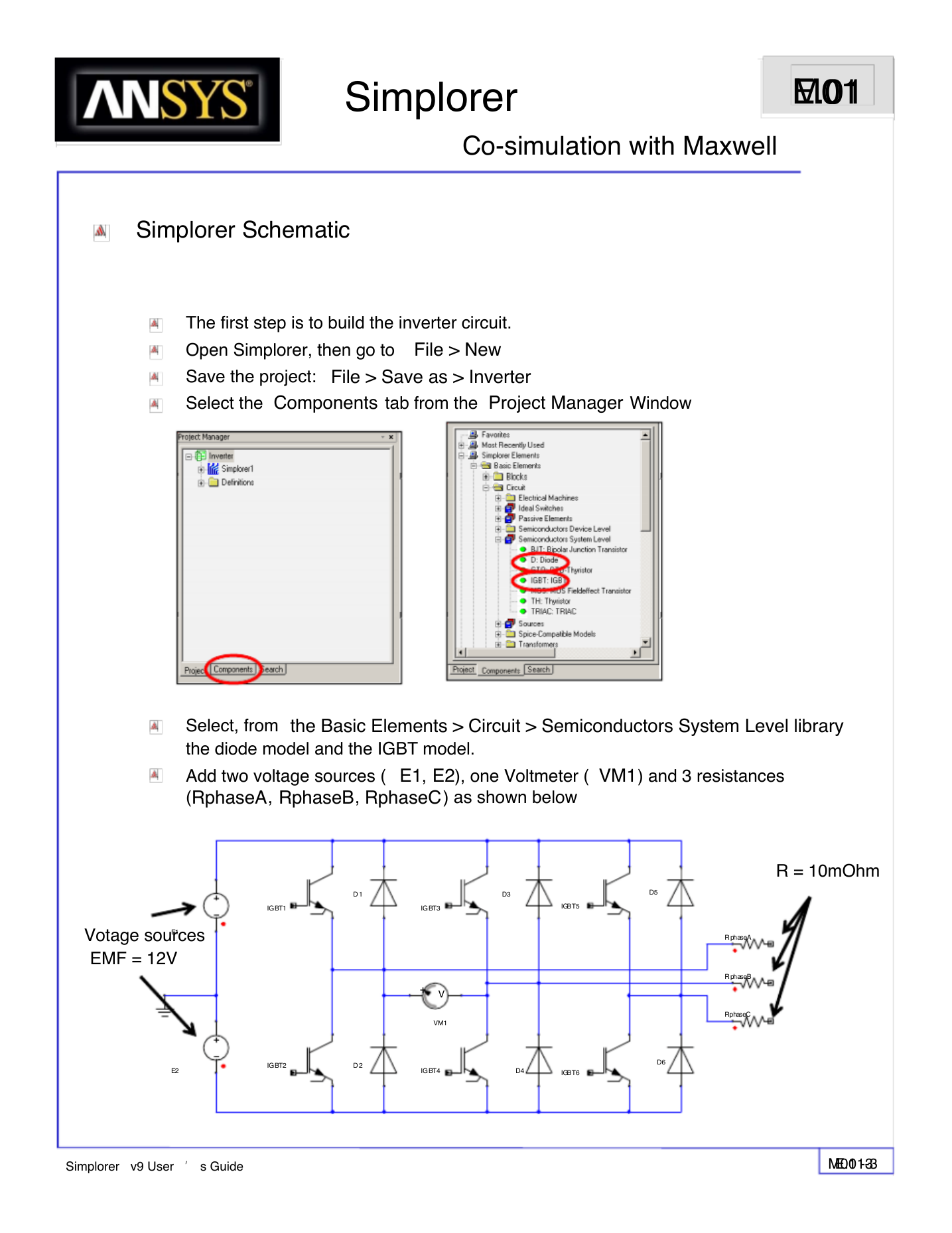
The first step is to build the inverter circuit.
Open Simplorer, then go to File > New
Save the project: File > Save as > Inverter
Select the Components tab from the Project Manager Window
Select, from the Basic Elements > Circuit > Semiconductors System Level library
the diode model and the IGBT model.
Add two voltage sources ( E1, E2), one Voltmeter ( VM1) and 3 resistances
(RphaseA, RphaseB, RphaseC) as shown below
IGBT1
IGBT3
IGBT5
D 1
D3
D5
Votage sources
EMF = 12V
E1
+ V
VM1
E2
IGBT2
D 2
IGBT4
D4
IGBT6
D6
R = 10mOhm
R phaseA
R phaseB
RphaseC
Simplorer v9 User ’ s Guide
E.01-3
M01 -3
�
Simplorer
E.01
M01
Co-simulation with Maxwell
Simplorer Schematic
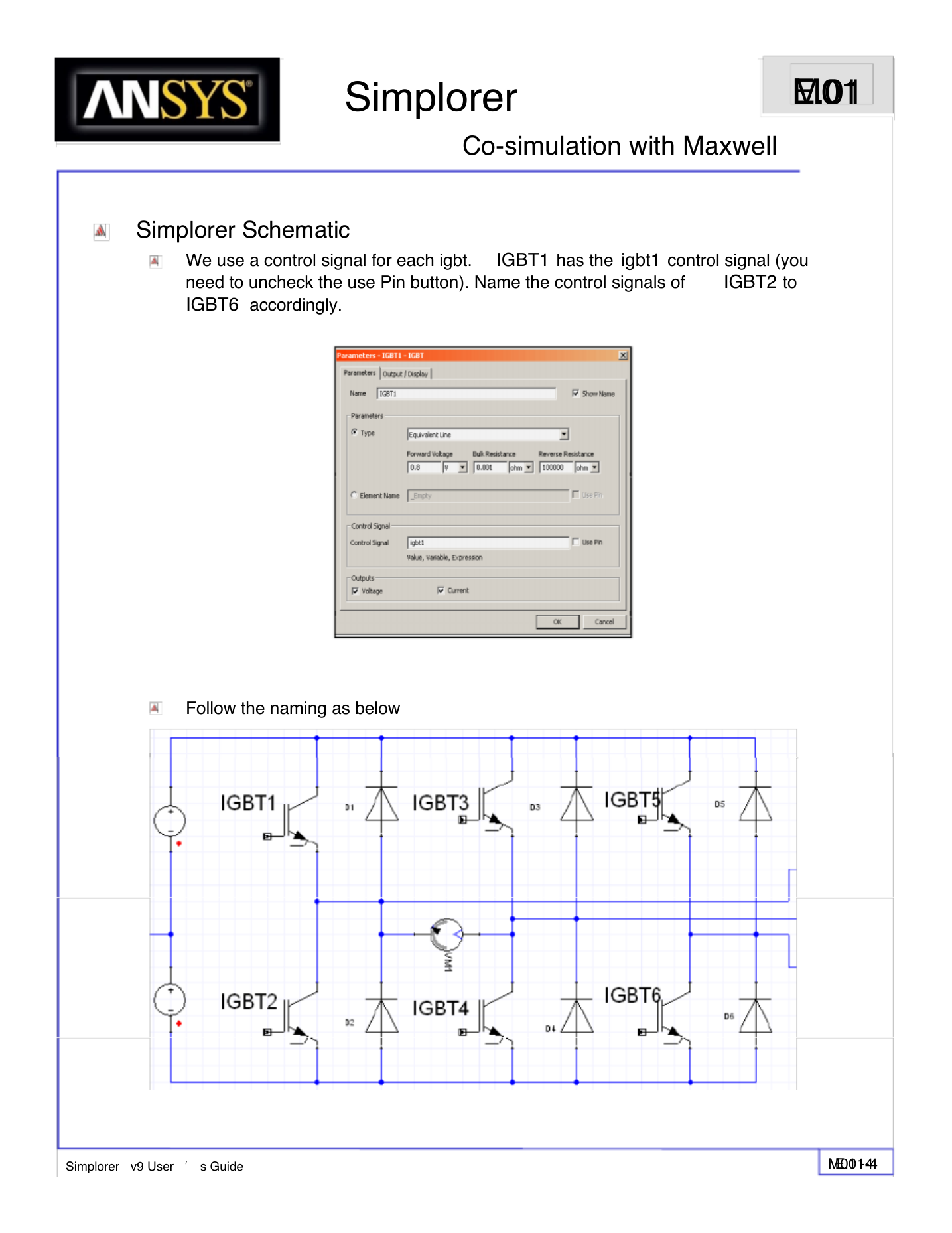
We use a control signal for each igbt.
need to uncheck the use Pin button). Name the control signals of
IGBT6 accordingly.
IGBT1 has the igbt1 control signal (you
IGBT2 to
Follow the naming as below
Simplorer v9 User ’ s Guide
E.01-4
M01 -4
�
Simplorer
E.01
M01
Co-simulation with Maxwell
Simplorer Schematic
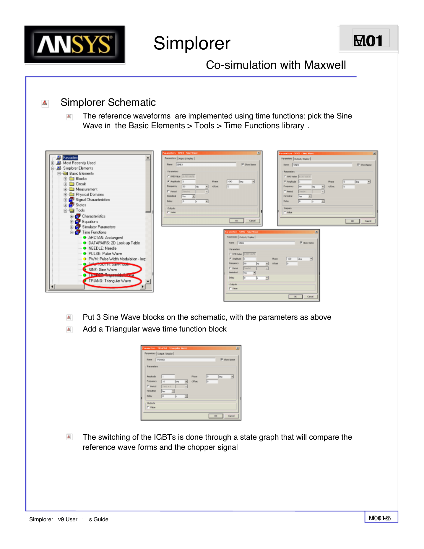
The reference waveforms are implemented using time functions: pick the Sine
Wave in the Basic Elements > Tools > Time Functions library .
Put 3 Sine Wave blocks on the schematic, with the parameters as above
Add a Triangular wave time function block
The switching of the IGBTs is done through a state graph that will compare the
reference wave forms and the chopper signal
Simplorer v9 User ’ s Guide
E.01-5
M01 -5
�
Simplorer
E.01
M01
Co-simulation with Maxwell
Simplorer Schematic
Simplorer Schematic
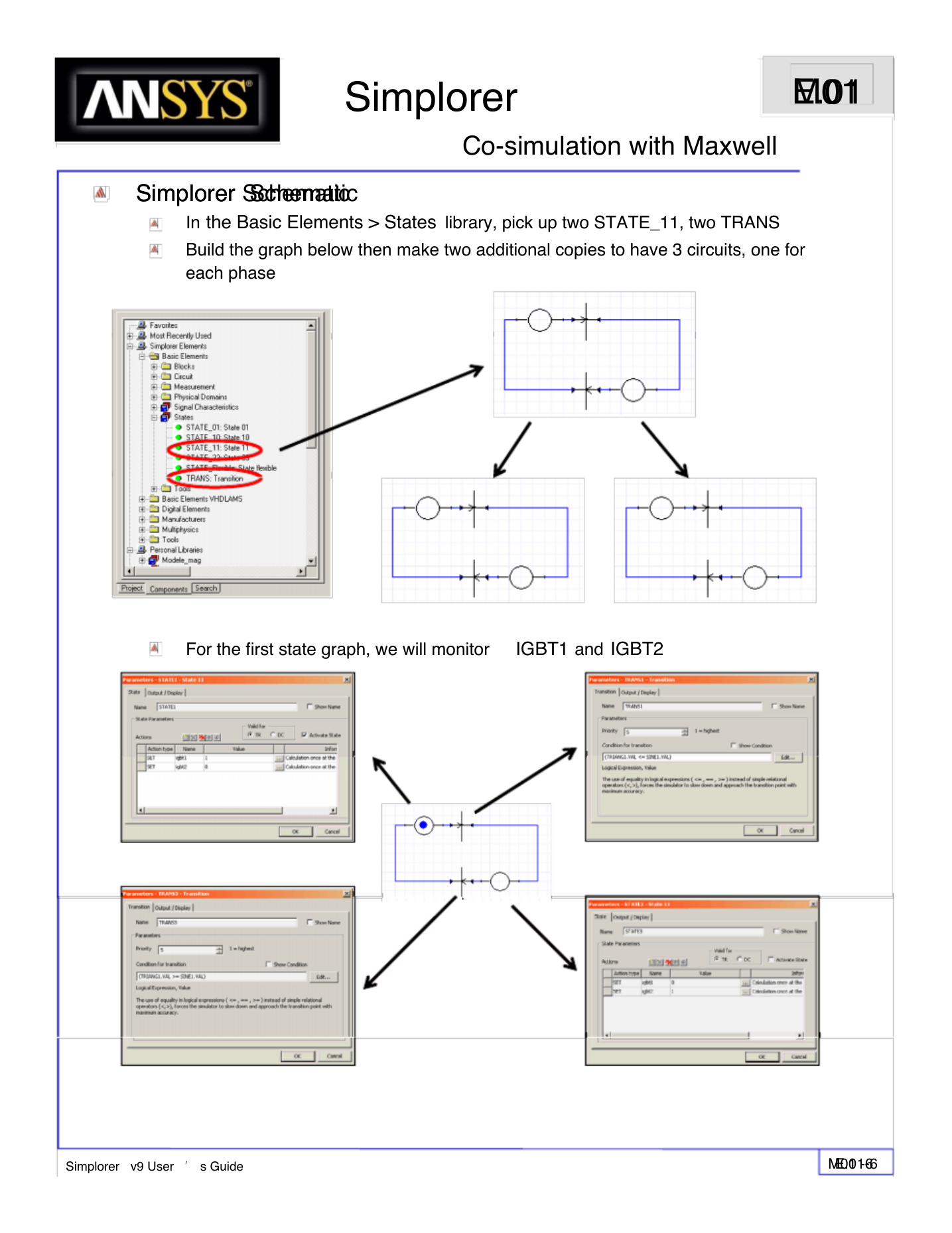
In the Basic Elements > States library, pick up two STATE_11, two TRANS
Build the graph below then make two additional copies to have 3 circuits, one for
each phase
For the first state graph, we will monitor
IGBT1 and IGBT2
Simplorer v9 User ’ s Guide
E.01-6
M01 -6
�
Simplorer
E.01
M01
Co-simulation with Maxwell
Simplorer Schematic
Fill the rest of the graphs: the second state graph monitors
and third state graph monitors
the second and third state graph are the SIN2 and SIN3 blocks respectively.
y
The inverter looks like this:
IGBT3 and IGBT4
IGBT5 and IGBT6. The reference waveforms for
g p
p
SINE1
SINE2
SINE3
TRIANG1
E1
E2
IGBT1
D7
IGBT3
D9
IGBT5
D11
+ V
VM1
R37
R43
R48
IGBT2
D8
IGBT4
D10
IGBT6
D12
Simplorer v9 User ’ s Guide
E.01-7
M01 -7
�
Simplorer
E.01
M01
Co-simulation with Maxwell
Mawell Project
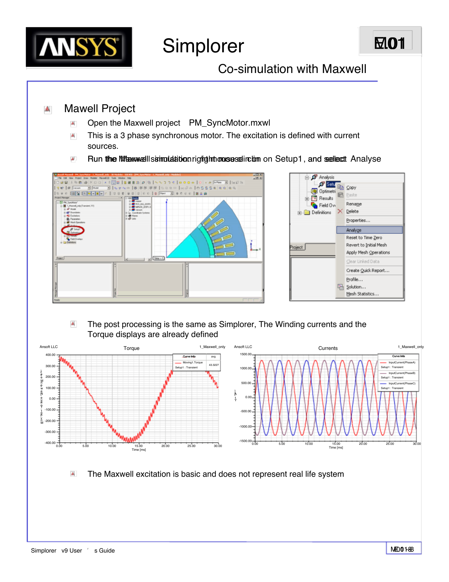
Open the Maxwell project PM_SyncMotor.mxwl
This is a 3 phase synchronous motor. The excitation is defined with current
sources.
Run the Maxwell simulation: right mouse clin on
Run the Maxwell simulation: right mouse clin on
and select
Setup1, and select Analyse
Ansoft LLC
400.00
300.00
200.00
100.00
0.00
-100.00
-200.00
-300.00
r]
te
e
nM
to
w
e
[N
e
rqu
.To
g1
in
ov
M
-400.00
0.00
The post processing is the same as Simplorer, The Winding currents and the
Torque displays are already defined
Torque
1_Maxwell_only
Ansoft LLC
Currents
1_Maxwell_only
Curve Info
Curve Info
avg
Moving1.Torque
Setup1 : Transient
43.3227
1500.00
1000.00
500.00
0.00
-500.00
-1000.00
]
[A
1
Y
Curve Info
Curve Info
InputCurrent(PhaseA)
Setup1 : Transient
InputCurrent(PhaseB)
Setup1 : Transient
InputCurrent(PhaseC)
Setup1 : Transient
5.00
10.00
15.00
Time [ms]
20.00
25.00
30.00
-1500.00
0.00
5.00
10.00
15.00
Time [ms]
20.00
25.00
30.00
The Maxwell excitation is basic and does not represent real life system
Simplorer v9 User ’ s Guide
E.01-8
M01 -8
�



 2023年江西萍乡中考道德与法治真题及答案.doc
 2012年重庆南川中考生物真题及答案.doc
 2013年江西师范大学地理学综合及文艺理论基础考研真题.doc
 2020年四川甘孜小升初语文真题及答案I卷.doc
 2020年注册岩土工程师专业基础考试真题及答案.doc
 2023-2024学年福建省厦门市九年级上学期数学月考试题及答案.doc
 2021-2022学年辽宁省沈阳市大东区九年级上学期语文期末试题及答案.doc
 2022-2023学年北京东城区初三第一学期物理期末试卷及答案.doc
 2018上半年江西教师资格初中地理学科知识与教学能力真题及答案.doc
 2012年河北国家公务员申论考试真题及答案-省级.doc
 2020-2021学年江苏省扬州市江都区邵樊片九年级上学期数学第一次质量检测试题及答案.doc
 2022下半年黑龙江教师资格证中学综合素质真题及答案.doc