2012 IEEE 16th International Symposium
2012 ISCE 1569579313
THE OPTIMIZATION CAPACITY OF THE MU-MIMO WITH
CHANNEL QUALITY INFORMATION
Jean-Baptiste YAMINDI Hong Ji Wu Mu-qing
jbyamindi@yahoo.fr jihong@bupt.edu.cn wumuqing@bupt.edu.cn
Institute, School of Information & Telecom. Engineering Beijing University of Posts and Telecommunications, Beijing, CHINA
In this paper our main work focus is on feedback v
Channel Quality Information (CQI) in order to optimize the
MU-MIMO transmissions operation as important to further
enhance system capacity. The rest of paper is organized as
follows: the Signal Model and Transmission Schemes in
Section II; System Proceeding of feedback information in
section III; the PMI/CQI feedback in section IV; section V on
Zero Forced Precoder Technology for feedback; section VI
analyzes and provides simulation results and section VII is
the conclusion.
II. SIGNAL MODEL AND TRANSMISSION SCHEMES
By the consideration of the signal model for the DL MIMO
transmission, the receiver known as eNodeB is designed with
a
precoder which each terminal can use to get the
information for its own data stream reception.
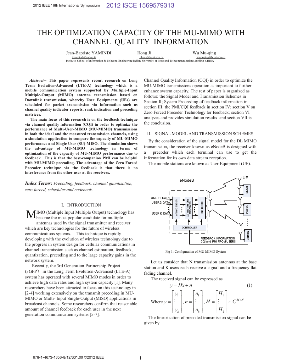
The mobile stations are known as User Equipment (UE).
eNodeB
UE
Abstract-- This paper represents recent research on Long
Term Evolution-Advanced (LTE-A) technology which is a
mobile communication system supported by Multiple-Input
Multiple-Output (MIMO) antenna transmission based on
Downlink transmission, whereby User Equipments (UEs) are
scheduled for packet transmission via information such as
channel quality indicator reports, rank indication and precoding
matrices.
The main focus of this research is on the feedback technique
via channel quality information (CQI) in order to optimize the
performance of Multi-User-MIMO (MU-MIMO) transmissions
in both the ideal and the measured transmission channels, using
a simulation application to compare the capacity of MU-MIMO
performance and Single User (SU)-MISO. The simulation shows
the advantage of MU-MIMO
terms of
optimization of the capacity of MU-MIMO performance due to
feedback. This is that the best-companion PMI can be helpful
with MU-MIMO precoding. The advantage of the Zero Forced
Precoder technique via the feedback is that there is no
interference from the other user at the receivers.
Index Terms: Precoding, feedback, channel quantization,
zero forced, scheduler and codebook.
technology
in
I. INTRODUCTION
M
IMO (Multiple Input Multiple Output) technology has
become the most popular candidate for multiple
antennas used by the signal transmitter and receiver
which are key technologies for the future of wireless
communications systems. This technique is rapidly
developing with the evolution of wireless technology due to
the progress in system design for cellular communications in
channel transmission such as channel estimation, feedback,
quantization, precoding and to the large capacity gains in the
network system.
Recently, the 3rd Generation Partnership Project
(3GPP� in the Long Term Evolution-Advanced (LTE-A)
system has operated with several MIMO modes in order to
achieve high data rates and high system capacity [1]. Many
researchers have been attracted to focus on this technology in
[2-4] working extensively on the transmit precoding in MU-
MIMO or Multi- Input Single-Output (MISO) applications in
broadcast channels. Some researchers confirm that reasonable
amount of channel feedback for each user in the next
generation communication systems [5-7].
978-1-4673-1356-8/12/$31.00 ©2012 IEEE
1
Fig 1: Configuration of MU-MIMO System
Let us consider that N transmission antennas at the base
station and K users each receive a signal and a frequency flat
fading channel.
The received signal can be expressed as
=
y Hx n
⎡
y
1
⎢
= ⎢
M
⎢
y
⎣
⎤
⎥
⎥
⎥
⎦
n
,
k
+ (1)
⎡
n
1
⎢
= ⎢
M
⎢
n
⎣
k
⎤
⎥
⎥
⎥
⎦
,
H
=
⎡
H
⎢
M
⎢
⎢
H
⎣
1
k
⎤
⎥
⎥
⎥
⎦
∈
C
M N
×
Where
y
The linearization of precoded transmission signal can be
given by
�
Where
K
x
= ∑
kW C ×∈
W s
k k
(2)
∈
and
ks C ×
1km
=
k
1
N m
are respectively, the
k
km streams and the linear Precoding Matrix
kW should be the linear decoding matrix
data vector with
for the k th user and
for the k th user.
The decoding output of the k th user is then given by
ˆ
s W H x n
(3)
k
k
H
k
kW is generally determined according to the
=
Where
(
H
+
)
k
chosen precoding design criterion.
III. SYSTEM PROCESS OF FEEDBACK INFORMATION
The eNodeB of this system receives k users’ data which
constitute users groups; those users’ groups send the data
information for scheduling to the schedule and multiplex
section, after scheduling it can be precoded. The feedback
information of the users to the eNodeB can be switched by the
controller of the user group, schedule and multiplex and
precoding.
A. Transmit pilot with precoder
At the beginning of each frame, eNodeB sends pilots to
every UE through a broadcast channel multiplied by the
precoder from the codebook; these pilots are used for channel
estimation.
B. Channel estimation for PMI and CQI
The channel estimation for all antennas is made at a
common resource element in each Resource Block (RB) based
on Channel State Information-Reference Signals (CSI-RS)
which can get information due to the Precoding Matrix
Indicator (PMI) and rank selection and CQI measurement.
The PMI and CQI are both computed and reported per sub-
band.
IV. PMI/CQI FEEDBACK
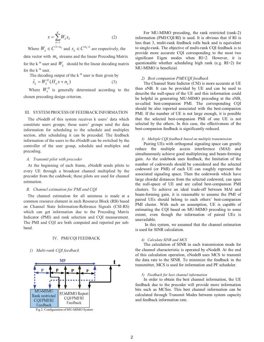
1) Multi-rank CQI feedback
Fig 2: Configuration of MU-MIMO System
2
For MU-MIMO precoding, the rank restricted (rank-2)
information (PMI/CQI/RI) is used. It is obvious that if RI is
less than 3, multi-rank feedback rolls back and is equivalent
to single-rank. The objective of multi-rank CQI feedback is to
provide more accurate CQI corresponding to the most two
significant Eigen modes when RI>2. However,
is
questionable whether scheduling high rank (e.g. RI>2) for
MU-MIMO is beneficial.
it
2) Best companion PMI/CQI feedback
The Channel State Indictor (CSI) is more accurate at UE
than eNB. It can be provided by UE and can be used to
describe the null-space of the UE and this information could
be helpful in generating MU-MIMO precoding at the eNB,
so-called best-companion PMI. The corresponding CQI
should be also reported associated with the best-companion
PMI. If the number of UE is not large enough, it is possible
that the selected best-companion PMI of one UE is not
selected by the others. In this case, the effectiveness of the
best-companion feedback is significantly reduced.
interference
the multiple access
3) Multiple CQI feedback based on multiple transmission
Pairing UEs with orthogonal signaling space can greatly
reduce
(MAI) and
simultaneously achieve good multiplexing and beam-forming
gain. As the codebook uses feedback, the limitation of the
number of codewords should be considered and the selected
codeword (or PMI) of each UE can roughly represent the
associated signaling space. Then the codewords which have
large chordal distances from the selected codeword, can span
the null-space of UE and are called best-companion PMI
clusters. To achieve an ideal trade-off between MAI and
beam-forming gain, it is reasonable to assume the PMI of
paired UEs should belong to each others’ best-companion
PMI cluster. With such an assumption, UE is capable of
estimating the CQI based on MU-MIMO precoding to some
extent, even though the information of paired UEs is
unavailable.
In this system, we assumed that the channel estimation
is used for SINR calculation.
4) Calculate SINR and MCS
The calculation of SINR in each transmission mode for
the channel characteristic is operated by eNodeB. At the end
of this calculation operation, eNodeB uses MCS to transmit
the data rate to the SINR. To minimize the feedback in the
transmitter, MCS is used for information and PF scheduler.
5) Feedback for best channel information
In order to obtain the best channel information, the UE
feedback due to the precoder will provide more information
bits such as MCSes. This best channel information can be
calculated through Transmit Modes between system capacity
and feedback information rate.
�
6) Scheduling for grouping Ues
The eNodeB which is the central controller can estimate
MU SNR from the reported MCS, one benefit of this
technique is to correct the actual number of scheduled layers.
When grouping G UEs together for MU transmission, the
eNB estimates the SNR by
mu
(
rG
(4)
SNR
SNR
cqi
=
)
Where SNR (mu-cqi) is the SNR corresponding to the
reported MU-CQI. The CQI feedback is utilized for both SU-
MIMO and MU-MIMO for signal transmission process.
7) Transmitting and Receiving signal
As the eNodeB transmits a signal to a selected user in a
selected transmit mode, eNodeB can calculate error-rate and
throughput for performance evaluation. The eNodeB updates
each user’s PF value and comes to the next frame.
Precoding is performed at the Physical Resource Block
(PRB), in terms of timing and synchronization during the
process, the received signal at the UE for the k th PRB can be
represented by:
H k E k X k
( )
(5)
Where H(k) is the complex channel transmission, E(k) is
the Precoding Matrix, X(k) is the transmit vector and N(k) is
the Additive White Gaussian Noise (AWGN).
Y k
( )
N K
( )
( )
+
=
(
)
More specifically, it is assumed that the reported PMI of
Aw and its best-companion PMI cluster,
UE A is denoted by
consisting of n codewords, is given as [
w
,L
w
.
]
,
1A
An
Firstly, the signal to noise ratio (SINR) based on SU-
2
, where
Hw
A
N
MIMO hypothesis is obtained by
SINR
SU =
H is the channel matrix of UE A, N represent the normalized
AWGN and inter-cell interferences. With information of best-
companion PMI cluster, the MU-MIMO based SINR can be
obtained as
2
n
∑
1
n
Hu
+
2
,
u
=
}
=
=
1i
MU
N
SINR
, (6)
(
)Ai
wwf
represents a generic MU-MIMO precoder
A
Hu
Ai
where MU-MIMO precoder{
u
( )•f
generator. For example, if Zero Forced (ZF) precoder is
assumed,
(
(
(
,
norm
wwf
HHH
]Ai
,
A wwH
Where
)1
)
−σ+
I
)
=
[
=
and
,
.
Ai
Ai
H
A
,
A
A
2
The CQI/SINR based on MU-MIMO can be reported in
addition to SU-MIMO feedback to facilitate MU-MIMO CQI
adjustment. It is noted that with a certain chordal distance
threshold assumed, the best-companion PMI cluster can be
implicitly known at both UE and eNodeB and, therefore, no
feedback is required. For example, when the chordal distance
threshold is set to one, the codewords, which are orthogonal
to the selected PMI, are defined as the best-companion PMI
cluster; the best-companion PMI cluster is pre-determined.
V. ZERO FORCED PRECODER TECHNOLOGY FOR
FEEDBACK AND THE OPTIMIZATION OF CAPACITY
OF MU-MIMO
In this section we will mainly focus on the fact that the
advantage of the Zero Forced Precoder technique via feedback
is that there is no interference from the other user at the
receivers, so the received signal is free from multi-user
interference. But in some cases of MU, interference can exist
due to the channel quantization and feedback delay.
The singular value decomposition (SVD) of the channel H
= ∑ where the matrices U and V
is given by of the
are unitary; the SVD decouples the channel into orthogonal
directions.
H U V
H
The equivalent channel quantization for k th user is
c
e k
,
=
,e kH and computed as
denoted by
cσν
H
H H
k
k
arg max
Where c is a vector that belongs to the codebook,
(7)
kσ the
first element of the main diagonal of ∑ and ν is denotes
the first column of V.
A. The ZF precoding technology
The ZF precoding technology is very important in MU-
MIMO potential precoder design and it can pre-cancel the
interference at the transmitter.
The ZF precoder can be designed using the Moore-
Penrose
Pseudo-inverse as
H
e
T
T
T
,1
,
,2
=
⎡
=⎣
⎡
= ⎣
e
...,
H
e
H
T
e N
,
W W W
T
(
H H
T
T
e
e
,1,
,2,
W H H H −
)
1
⎤
H
⎦ and
e
(8)
W
,...,
Where
The ZF precoder is obtained when the equivalent
channel observed by different users are orthogonal to each
other.
This technique is key to MU-MIMO improvement between
beam-forming gain and the required amount of feedback
information [8].
⎤
⎦
T N
,
Additionally the linear precoding matrix applied with
the Singular Value Decomposition method (SVD) and the
Leakage of MMSE at eNodeB can be also considered.
In the case of the LMMSE receiver, the k th user is given by
(9)
W W H H W H W
T
Iσ −
)
2
1
n
H
T k
,
H
k
=
+
(
(
)
H
R
k
2σ is the noise variance.
T
k
Where
SNR can be defined by MMSE receiver combiners and can
be formulated as
⎛
g
⎜
⎝
⎞
⎟
⎠ (10)
H t H t
k k
H t
k k
β
)(
k k
=
+
−
1
I
(
)
(
)
H
H
N
k
The combination of ZF precoder with Leakage of
3
�
MMSE at eNodeB and (SVD) can reduce the interference and
improve system performance.
B. The optimization of the capacity MU-MIMO
The optimization of the capacity MU-MIMO can be
obtained by the codebook and feedback with index. The UE
feeds back a Channel Quality Indicator (CQI) value for every
matrix in the codebook, which gives more flexibility and
accurate CQI information for scheduling. Based on the
feedback, the scheduler which provides more accurate CQI
information at eNodeB chooses the precoding matrix with the
highest sum capacity and applies it to the PRB.
The SINR for each data stream can be calculated as:
SINR
MMSE
m
=
′
′
ε
E k H k
( )
( )
s
×
MN G
MMSE
k
(
o
)
The achievable data rate for PRB k is given by:
r
k
log (1
2
+
SINR
m
)
(12)
rN
∑
=
m
This highest sum capacity and application to the PRB
produce considerable improvements in error performance.
VI. SIMULATION
In this section, we will compare the performance of SU-
MIMO/MU-MIMO through Channel Quality Indicator.
In order to operate on the same simulation platform for
the performance of both SU-MISO and MU-MIMO at high
SNR, with the multiplexing gain of the MU-MIMO system is
twofold while it is limited to one for the SU-MISO. We
assume that for both the ideal and the measured channels,
MU-MIMO yields a higher sum rate than SU-MISO, and all
frames and all subcarriers are subsequently normalized to
bps/Hz.
TABLE
SIMULATION PARAMETER
Parameter
Center Frequency
Bandwidth
eNB transmission power
Number of UEs
Number of subcarriers
Downlink transmission
scheme
Downlink scheduler
Feedback assumptions
Value
1917.5 Mhz
4.8 Mhz
30dBm
2
160
Dynamic SU/MU-MIMO
scheduling:MU-MIMO pairing:
Max 2 users/RB;
PF in time and frequency
5ms periodicity and 4ms delay;
Sub-band CQI and PMI
feedback without errors.
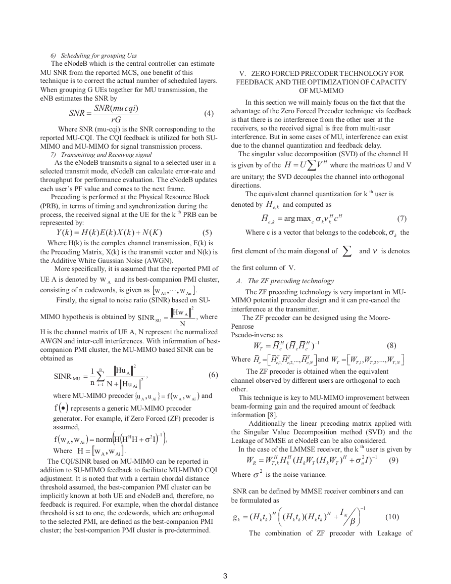
We will compare the capacity of SU-MISO TDMA and
MU-MIMO with two UEs as shown below:
−
1
(11)
0
0
5
10
15
SNR(dB)
20
25
30
Comparison of SU-MISO and MU-MIMO capacitry
SU-MISO ideal
SU-MISO mesured
MU-MIMO ZF ideal
MU-MIMO ZF mesured
18
16
14
12
10
8
6
4
2
)
s
p
b
(
t
u
p
h
g
u
o
r
h
t
Fig 3: Ergodic sum-rate capacity of SU-MISO TDMA and MU-MIMO with
two UEs.
In this result, since these correlation effects result in a
rank-deficient channel matrix in quantized beam-forming, it
shows that MU-MIMO with ZF filter can be used to the
minimum-correlation precoder so MU-MIMO with ZF
measured channel is much higher than in the single-user SU-
MISO. In that case, MU-MIMO power normalization is
performed.
It is seen that the proposed optimized linear precoder
offers a significant gain over the other schemes.
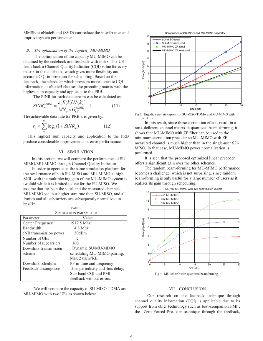
The random beam-forming for MU-MIMO performance
becomes a challenge, which is not surprising, since random
beam-forming is only useful for a large number of users as it
realizes its gain through scheduling.
QLP for MU-MIMO with 128 quantization vectors
4x1 MU-MIMO
4x2 MU-MIMO
4x3 MU-MIMO
18
16
14
12
10
8
6
4
)
s
p
b
(
t
u
p
h
g
u
o
r
h
t
2
0
5
10
15
SNR(dB)
20
25
30
Fig 4: MU-MIMO with quantized beamforming,
VII. CONCLUSION
Our research on the feedback technique through
channel quality information (CQI) is applicable due to its
support from other technology such as best-companion PMI ,
the Zero Forced Precoder technique through the feedback,
4
�
the channel quantization and feedback, the Singular Value
Decomposition method (SVD) and the Leakage of Minimum
Mean Square Error (MMSE) at eNodeB, which all contribute
to optimize the capacity of MU-MIMO channel transmissions
performance. The simulation results show clearly that the
capacity of MU-MIMO channel transmissions performance
using the ideal and the measured transmission channels
compare to Single User (SU)-MISO is superior.
Therefore MU-MIMO channel transmission is a beneficial
technology
the capacity of
transmission performance using the feedback and there is no
interference from the other user at the receivers.
terms of optimizing
in
Our future work includes incorporating the proposed
Pairing UEs with orthogonal signaling space systems.
ACKNOWLEDGMENT
Thanks to Mr Thomas Maj for editorial assistance on
this paper, special thank to China Post Doctorate project for
sponsor.
REFERENCE
[1] 3GPP TR 36.211 V8.1.0, “Evolved universal terrestrial radio access
(EUTRA); physical channels and modulation,” http://www.3gpp.org,
Nov.2007.
[2] D. Bartolome, A. Pascual-Iserte and A. I. Perez-Neira, “Spatial scheduling
algorithms for wireless systems,” P ICASSP’03, April 2003.
[3] M. Fuchs, , G. Del Galdo, and M. Haardt, “Low-complexity space-
timefrequency scheduling for MIMO systems with SDMA,” IEEE Tr.
Vehic.Tech., Vol. 56, No. 5, pp. 2775-2784, Sept. 2005.
[4] E. Viterbo and A. Hottinen, “Optimal user pairing for multiuser MIMO,”
submitted
[5] Philips � “Comparison between MU-MIMO codebook-based channel
in 3GPP TSG RAN
for LTE downlink,”
reporting
WG1#46bis/R1-062483.
techniques
[6] Samsung Electronics, “Downlink MIMO for EUTRA,” in 3GPP TSG
[7] Samsung Electronics, “Downlink MIMO Schemes for IEEE802.16m,” in
[8] Performance of Linear Multi-User MIMO Precoding in LTE System, 2008
RAN WG1 #44/R1-060335.
IEEE C802.16m-08/285.
IEEE
BIOGRAGHIES
Jean-Baptiste YAMINDI born in Central African
Republic, received his B.E. degree in Math-Physics in
2001, Learned Chinese language from 2002-2003 at
Beijing University of Language and Culture (BLCU),
got M.E. degree in System of Information and
Telecommunication and PhD degree
in BUPT
research interests area WiMAX Physical Layer from
Beijing
and
Telecommunications(BUPT) in 2006, 2010 CHINA.
2011 Algorithm Conception Engineer
the
Downlink system for the Long Term Evolution-
Advanced
(LTE-A)technology, System Planning
Division-Radio Access Technology Division, Potevio Institute of Technology Co.
Ltd, Beijing, CHINA.
University
Posts
of
in
of
Posts
Beijing
University
Wu Mu-Qing, born in July 1963, Ph.D, professor
of
and
Telecommunications (BUPT), senior membership of
China institute of communications. Now, he was
interested and researching
in Ad Hoc wireless
network, UWB, high-speed network traffic control
and performance analysis, GPS locating and services,
teaching basic theories of telecom networks
in
and
information
Hong Ji (SM’09) received the B.S. degree in
communications engineering and the M.S. and Ph. D
degrees
communications
engineering from the Beijing university of Posts and
Telecommunications (BUPT), Beijing, China, in
1989, 1992, and 2002, respectively. From June to
December 2006, she was a Visiting Scholar with the
University of British Columbia, Vancouver, BC,
Canada. She is currently a Professor with BUPT. She
is also engaged with national science research projects,
including Hi-Tech Research and Development
Program of China (863 program) and the National Natural Science Foundation
of China. Her research interests include heterogeneous networks, peer-to-peer
protocols, cognitive radio networks, and cooperative communication. Prof. Ji
serves on the editorial boards of several journals, including the Wiley
International Journal of Wireless Communications and Mobile Computing, the
Wiley International Journal of Communication Systems. She has also served on
the Technical Program Committee (TPC) of numerous conferences, e.g., as a
TPC of the 2010/2011 IEEE International Conference on Communications, the
2010/2011 IEEE Global Communications Conference, the 2010 /2011 IEEE
INFOCOM workshop, the 2007 IEEE VTC, and as a TPC Cochairs of the 2011
CHINACOM Workshops.
5
�


 2023年江西萍乡中考道德与法治真题及答案.doc
 2012年重庆南川中考生物真题及答案.doc
 2013年江西师范大学地理学综合及文艺理论基础考研真题.doc
 2020年四川甘孜小升初语文真题及答案I卷.doc
 2020年注册岩土工程师专业基础考试真题及答案.doc
 2023-2024学年福建省厦门市九年级上学期数学月考试题及答案.doc
 2021-2022学年辽宁省沈阳市大东区九年级上学期语文期末试题及答案.doc
 2022-2023学年北京东城区初三第一学期物理期末试卷及答案.doc
 2018上半年江西教师资格初中地理学科知识与教学能力真题及答案.doc
 2012年河北国家公务员申论考试真题及答案-省级.doc
 2020-2021学年江苏省扬州市江都区邵樊片九年级上学期数学第一次质量检测试题及答案.doc
 2022下半年黑龙江教师资格证中学综合素质真题及答案.doc